AFRISO DIT 10 Operating Instructions Manual
Digital tank contents indicator
Hide thumbs
Also See for DIT 10:
- Operating instructions manual (115 pages) ,
- Operating instructions manual (116 pages)
Advertisement
Available languages
Available languages
Quick Links
Advertisement

Subscribe to Our Youtube Channel
Related Manuals for AFRISO DIT 10


Summary of Contents for AFRISO DIT 10
- Page 1 Wersja: 02.2022.0 ID: 900.000.0740...
- Page 30 Copyright 2022 AFRISO-EURO-INDEX GmbH. Alle Rechte vorbehalten. Version: 02.2022.0 ID: 900.000.0740...
- Page 31 Diese Betriebsanleitung beschreibt den digitalen Tankinhaltsanzeiger „DIT 10“ (im Folgenden auch „Produkt“). Diese Betriebsanleitung ist Teil des Produkts. • Sie dürfen das Produkt erst benutzen, wenn Sie die Betriebsanleitung vollständig gelesen und verstanden haben. • Stellen Sie sicher, dass die Betriebsanleitung für alle Arbeiten an und mit dem Produkt jederzeit verfügbar ist.
- Page 32 Warnhinweise sind in dieser Betriebsanleitung mit Warnsymbolen und Sig- nalwörtern gekennzeichnet. Abhängig von der Schwere einer Gefährdungs- situation werden Warnhinweise in unterschiedliche Gefahrenklassen unter- teilt. HINWEIS macht auf eine möglicherweise gefährliche Situation aufmerksam, die bei Nichtbeachtung Sachschäden zur Folge haben kann. DIT 10...
- Page 33 Führen Sie bei der Verwendung des Produkts alle Arbeiten ausschließlich unter den in der Betriebsanleitung und auf dem Typenschild spezifizierten Bedingungen und innerhalb der spezifizierten technischen Daten und in Übereinstimmung mit allen am Einsatzort geltenden Bestimmungen, Normen und Sicherheitsvorschriften durch. DIT 10...
- Page 34 Gefährdungen auftreten können, die nicht direkt vom Produkt ausge- hen. Führen Sie ausschließlich solche Arbeiten an und mit dem Produkt durch, die in dieser Betriebsanleitung beschrieben sind. Nehmen Sie keine Verände- rungen vor, die in dieser Betriebsanleitung nicht beschrieben sind. DIT 10...
- Page 35 Umgebungsbedingungen eingehalten werden. • Benutzen Sie für den Transport die Originalverpackung. • Lagern Sie das Produkt nur in trockener, sauberer Umgebung. • Stellen Sie sicher, dass das Produkt bei Transport und Lagerung stoßge- schützt ist. DIT 10...
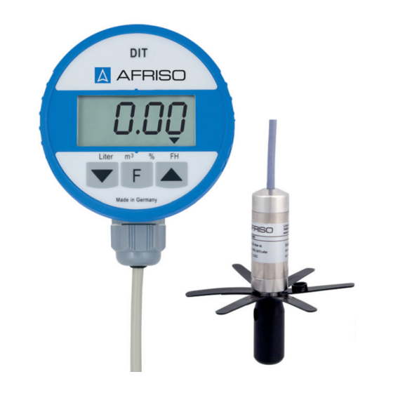
- Page 36 Das Produkt besteht aus einem Auswertegerät mit Digitalanzeige und einer Tauchsonde mit Drucksensor. A. Display B. Programmiertasten C. Funktionstaste D. Kabelverschraubung E. Kabel A. Kabel mit Entlüftungsschlauch B. Drucksensor C. Stern D. Abstandhalter DIT 10...
- Page 37 Spannungssignal um. Das Spannungssignal wird an das Aus- wertegerät gesendet. Das Auswertegerät berechnet aus dem Spannungssignal den Inhalt des Tanks und zeigt im Display den Tankinhalt (in Liter, Kubikmeter, Prozent, Füllhöhe) an. Das Produkt entspricht: • EMV-Richtlinie (2014/30/EU) • RoHS-Richtlinie (2011/65/EU) DIT 10...
- Page 38 -5 ... 80 °C Schutzart (EN 60529) IP 51 Nennspannung 3,6 V Versorgungsspannung über Batterie Lithium-Batterie 3,6 V Typ LS 14500, Li-metal *Genauigkeit des Gesamtsystems: ± 1,5 % FSO, IEC 60770, bezogen auf die Anzeige der Füllhöhe in mm. DIT 10...
- Page 39 Bereich 0 ... 70 °C Mediumstemperatur -5 ... 70 °C Umgebungstemperatur Lagerung -5 ... 70 °C Schutzart (EN 60529) IP 68 *Genauigkeit des Gesamtsystems: ± 1,5 % FSO, IEC 60770, bezogen auf die Anzeige der Füllhöhe in mm. DIT 10...
- Page 40 Ovale Kellertanks (beispielsweise GfK-Tanks oder Blechtanks) Kunststofftank mit Aus- Kunststofftanks mit großer Aus- nehmung nehmung in der Tankmitte (Herstel- ler: beispielsweise Roth, Werit) Tankform-Kennziffer:______________________ 1. Ermitteln Sie das Gesamtvolumen in Litern (siehe technischen Daten des Tanks). Tankvolumen:___________________________ Liter DIT 10...
- Page 41 1. Schrauben Sie die Feuchtraum-Abzweigdose mit den beiliegenden Schrauben fest. 2. Hängen Sie das Auswertegerät in den Wandhalter. 3. Führen Sie die Kabel (Drucksensorkabel und Kabel des Auswertegeräts) in die Feuchtraum-Abzweigdose. 4. Schieben Sie die Kabelverschraubung am Tank auf das Kabel des Druck- sensors. DIT 10...
- Page 42 Feuchtraum-Abzweigdose geführt wurden. 1. Verbinden Sie die Kabel mittels der Lüsterklemme. 2. Verschließen Sie die Feuchtraum-Abzweigdose. A. Kabel vom Auswertegerät B. Weiß (U+) C. Grün (Signal) D. Braun (U-) E. Gelb/schwarz (Schirm) F. Lüsterklemme G. Kabel vom Drucksensor DIT 10...
- Page 43 3. Drücken SIe den Resettaster (A) und halten Sie diesen gedrückt. 4. Stecken Sie den zweipoligen Bat- teriestecker in die zweipolige Buchse (B) auf der Leiterplatte. - Achten Sie auf die korrekte Polung. 5. Lassen Sie den Resettaster (A) wieder los. DIT 10...
- Page 44 - Der Wert wird auf 0.00 gesetzt. - Der Nullpunktabgleich kann in diesem Zustand beliebig oft durchgeführt werden. 3. Drücken Sie die Funktionstaste, um den Nullpunktabgleich zu beenden. - Am unteren Displayrand erscheint ein Pfeil, der auf die Einheit Liter zeigt. DIT 10...
- Page 45 2. Schrauben Sie mit dem Abstands- halter (A) den Stern (B) am Druck- sensor (C) fest. 3. Biegen Sie die Arme des Sterns über den Abstandshalter. 4. Schieben Sie den Drucksensor von oben durch das Tankan- schlussgewinde (D). DIT 10...
- Page 46 - Verwenden Sie zur Montage im Tank die für den jeweiligen Tank erfor- derlichen Teile des Kabelverschraubungssets. 2. Bestimmen Sie die Kabellänge wie oben beschrieben. 3. Ziehen Sie die Kabelverschraubung so fest, dass das Kabel nicht mehr verschoben werden kann und geruchsdicht fixiert ist. DIT 10...
- Page 47 A. Kabelverschraubung (PG 9) zur Fixierung des Kabels B. Einschraubkörper G1 / G Kabel- verschraubung (PG 9) C. Reduzierstück G1 - G1 D. Reduzierstück G2 - G1 E. Reduzierstück G1 - Rp1 F. Flachdichtung NBR G. Reduzierstück G2 - G1 DIT 10...
- Page 48 H. Stopfbuchse I. Scheibe Ø 17 J. Stopfen K. Einschraubkörper DIT 10...
- Page 49 Sie diese mit der Mut- ter. 3. Führen Sie das Kabel des Druck- sensors in die Kabelverschrau- bung (PG 9) (A) und ziehen Sie die Kabelverschraubung so fest, dass das Kabel nicht mehr ver- schoben werden kann und geruchsdicht fixiert ist. DIT 10...
- Page 50 - Bei Volumina > 9999 Liter wird der Wert mit einer Kommastelle in Kubikmetern (1000 Liter = 1 Kubikmeter) eingegeben. 4. Drücken Sie die Programmiertaste (Pfeil oben), um die Kommastelle zu verschieben. 5. Drücken Sie die Funktionstaste, um die Einstellung zu bestätigen. DIT 10...
- Page 51 Stelle zu ändern. 4. Drücken Sie die Funktionstaste, um die Einstellung zu bestätigen. Die Eingabe der Tankdaten ist abgeschlossen und das Auswertegerät wechselt in den Messbetrieb. - Das Symbol (beide Pfeile) in der linken oberen Ecke des Displays erlischt. DIT 10...
- Page 52 2. Korrigieren Sie die Tankdaten (siehe Kapitel "Tankdaten ermitteln"). - Wenn Sie keine Tankdaten verändern möchten, drücken Sie viermal die Funktionstaste, um in den Messmodus zurückzukehren. - Die Pfeile in der linken oberen Ecke des Displays sind aus. DIT 10...
- Page 53 1. Gehen Sie vor wie in Kapitel "Lithium-Batterie anschließen" beschrieben. - Die eingegebenen Tankdaten bleiben bei einem Batteriewechsel erhal- ten. Das Produkt ist geeignet für hochwassergefährdete Gebiete und ist druck- wasserdicht bis 10 mH O (1 bar Außendruck). Nach einer Überschwemmung muss das Produkt nicht getauscht werden. DIT 10...
- Page 54 Prüfen Sie den Batterie- nicht mit der Leiterplatte stecker (siehe Kapitel verbunden "Lithium-Batterie anschließen") Display wechselt zwi- Die Tankdaten sind Korrigieren Sie die schen dem angezeigten falsch eingegeben Tankdaten (siehe Kapi- Wert und „ “ hin und tel "Tankdaten einge- ben") DIT 10...
- Page 55 Reihenfolge). 2. Entnehmen Sie die Batterie (siehe Kapitel "Lithium-Bat- terie anschließen" in umgekehrter Reihenfolge). 3. Entsorgen Sie das Produkt und die Batterie getrennt. Vor einer Rücksendung Ihres Produkts müssen Sie sich mit uns in Verbin- dung setzen (service@afriso.de). DIT 10...
- Page 56 Informationen zur Gewährleistung finden Sie in unseren Allgemeinen Geschäftsbedingungen im Internet unter www.afriso.com oder in Ihrem Kauf- vertrag. • Verwenden Sie nur Original Ersatz- und Zubehörteile des Herstellers. Digitaler Tankinhaltsanzei- 52150 ger „DIT 10“ Ersatz-Batterie 68309 Ersatz-Tauchsonde 52153 (0/400 mbar) Außenbereich-Abzweig-...
- Page 57 DIT 10...
- Page 58 DIT 10...
- Page 59 Copyright 2022 AFRISO-EURO-INDEX GmbH. All rights reserved. Version: 02.2022.0 ID: 900.000.0740...
- Page 60 These operating instructions describe the digital tank contents indicator "DIT 10" (also referred to as "product" in these operating instructions). These operating instructions are part of the product. • You may only use the product if you have fully read and understood these operating instructions.
- Page 61 Safety messages in these operating instructions are highlighted with warning symbols and warning words. Depending on the severity of a hazard, the safety messages are classified according to different hazard categories. NOTICE indicates a hazardous situation, which, if not avoided, can result in equipment damage. DIT 10...
- Page 62 DIT 10...
- Page 63 Only perform work on and with the product which is explicitly described in these operating instructions. Do not make any modifications to the product which are not described in these operating instructions. DIT 10...
- Page 64 • Use the original packaging when transporting the product. • Store the product in a clean and dry environment. • Verify that the product is protected against shocks and impact during trans- port and storage. DIT 10...
- Page 65 The product consists of a control unit with a digital display and a submersible probe with a pressure sensor. A. Display B. Programming keys C. Function key D. Cable gland E. Cable A. Cable with vent hose B. Pressure sensor C. Star D. Spacer DIT 10...
- Page 66 The control unit calculates the content of the tank on the basis of the voltage signal and displays the content (in litres, cubic metres, percentage, liquid level). The product complies with: • EMC Directive (2014/30/EU) • RoHS Directive (2011/65/EU) DIT 10...
- Page 67 IP 51 Nominal voltage 3.6 V Supply voltage via battery Lithium battery 3.6 V Type LS 14500, Li-metal *Accuracy of the complete system with reference to the indication of the liquid level in mm: ±1.5 % FSO, IEC 60770. DIT 10...
- Page 68 -5 ... 70 °C Ambient temperature storage -5 ... 70 °C Degree of protection (EN 60529) IP 68 *Accuracy of the complete system with reference to the indication of the liquid level in mm: ±1.5 % FSO, IEC 60770. DIT 10...
- Page 69 Plastic tank with recess Plastic tanks with larger recesses in the tank centre (manufacturers: for example, Roth, Werit) Tank shape code:______________________ 1. Determine the total volume of the tank system in litres (see the techni- cal data of the tank). Tank volume:___________________________litres DIT 10...
- Page 70 2. Fit the control unit into the wall bracket. 3. Route the cable (pressure sensor cable and cable of the control unit) into the moisture-proof junction box. 4. Push the cable gland at the tank onto the cable of the pressure sensor. DIT 10...
- Page 71 1. Connect the cables using the terminal strip. 2. Close the moisture-proof junction box. A. Cable from control unit B. White (U+) C. Green (signal) D. Brown (U-) E. Yellow/black (shield) F. Terminal strip G. Cable from pressure sensor DIT 10...
- Page 72 3. Press the reset pushbutton (A) and hold it down. 4. Plug the two-pin battery connector into the two-pin socket (B) on the PCB. - Verify correct polarity. 5. Release the reset pushbutton (A). DIT 10...
- Page 73 - In this state, zero calibration can be performed any number of times. 3. Press the function key to terminate zero calibration. - An arrow pointing to the unit "Litres" is displayed at the bottom of the dis- play. DIT 10...
- Page 74 2. Use the spacer (A) to screw the star (B) to the pressure sensor (C). 3. Bend the arms of the star over the spacer. 4. Push the pressure sensor from the top though the tank connec- tion thread (D). DIT 10...
- Page 75 - For mounting to the tank, use the appropriate parts of the cable gland kit required for your specific tank. 2. Determine the cable length as described above. 3. Tighten the cable gland so that the cable can no longer be moved and that the connection is odour-tight. DIT 10...
- Page 76 A. Cable gland (PG 9) for holding the cable B. Screw fitting G1 / G cable gland (PG 9) C. Reducer G1 - G1 D. Reducer G2 - G1 E. Reducer G1 - Rp1 F. Flat gasket NBR G. Reducer G2 - G1 DIT 10...
- Page 77 H. Sealing gland I. Washer Ø 17 J. Gland K. Screw fitting DIT 10...
- Page 78 (PG 9) (A) and fasten it with the enclosed nut. 3. Route the cable of the pressure sensor trough the cable gland (PG 9) (A) and tighten the cable gland so that the cable can no longer be moved and that the connection is odour-tight. DIT 10...
- Page 79 - In the case of volumes > 9999 litres, the value is entered in cubic metres (1000 litres = 1 cubic metre) with a decimal place. 4. Use the programming key (arrow up) to move the decimal place. 5. Press the function key to confirm the setting. DIT 10...
- Page 80 4. Press the function key to confirm the setting. You have now entered all the tank data and the control unit switches to measurement mode. - The symbol (both arrows) is no longer displayed in the top left corner of the display. DIT 10...
- Page 81 - If you do not want to change any of the tank data, press the function key four times to return to the measuring mode. - The arrows are no longer displayed in the top left corner of the display. DIT 10...
- Page 82 - The tank data already stored are not cleared when the battery is replaced. The product is suitable for use in flood hazard areas; it is watertight up to 10 mH O (1 bar pressure). After a flood, the product does not have to be replaced. DIT 10...
- Page 83 Display shows even Short circuit in the con- Check the cable though the level is nection cable between higher the pressure sensor and the control unit Other malfunctions Contact the AFRISO service hotline DIT 10...
- Page 84 3. Dispose of the product and of the battery separately. Get in touch with us before returning your product (service@afriso.de). See our terms and conditions at www.afriso.com or your purchase contract for information on warranty. DIT 10...
- Page 85 • Only use genuine spare parts and accessories provided by the manufac- turer. Digital tank contents indica- 52150 tor "DIT 10" Spare battery 68309 Spare submersible probe 52153 (0/400 mbar) Outdoor junction box 31824 Cable gland kit + cable 52125...
- Page 86 DIT 10...
- Page 87 DIT 10...
- Page 88 Copyright 2022 AFRISO-EURO-INDEX GmbH. Tous droits réservés. Version: 02.2022.0 ID: 900.000.0740...
- Page 89 Cette notice technique contient la description de l'indicateur numérique de niveau de réservoir DIT 10 (dénommé ci-après "produit"). Cette notice tech- nique fait partie du produit. • Utilisez le produit seulement après que vous aurez lu et compris intégra- lement la notice technique.
- Page 90 En fonction de la gravité du risque les consignes de sécurité sont réparties dans diffé- rentes classes de risques. AVIS signale une situation potentiellement dangereuse qui, si elle n'est pas évitée, peut entraîner un dommage matériel. DIT 10...
- Page 91 Pendant l'utilisation du produit effectuez toutes les opérations exclusivement dans les conditions spécifiées dans cette notice technique et sur la plaque signalétique, conformément aux données techniques spécifiées et en accord avec tous les règlements, normes et consignes de sécurité en vigueur sur le lieu d'installation. DIT 10...
- Page 92 En travaillant sur le produit et avec celui-ci, effectuez exclusivement les opé- rations décrites dans cette notice technique. N'effectuez pas de modifica- tions non décrites dans cette notice technique. DIT 10...
- Page 93 • Utilisez l'emballage d'origine pour le transport. • Stockez le produit dans un lieu sec et propre. • Assurez-vous que le produit est à l'abri des chocs pendant le transport et le stockage. DIT 10...
- Page 94 Le produit est composé d'une unité de commande avec un affichage numé- rique et d'une sonde à immersion avec capteur de pression. A. Affichage B. Touches de programmation C. Touche de fonction D. Presse-étoupe E. Câble A. Câble avec tuyau B. Capteur de pression C. Croisillon D. Espaceur DIT 10...
- Page 95 L'unité de commande calcule le contenu du réservoir sur la base du signal de tension et affiche le contenu du réservoir (en litres, mètres cubes, pourcen- tage, niveau de remplissage). Le produit est conforme à : • Directive CEM (2014/30/UE) • Directive RoHS (2011/65/UE) DIT 10...
- Page 96 Tension d'alimentation par l'intermé- Pile au lithium 3,6 V diaire d'une pile Type LS 14500, Li-metal *Précision du système complet relative à la hauteur du niveau de remplissage en mm : ±1,5 % sortie plein échelle FSO, IEC 60770. DIT 10...
- Page 97 -5 ... 70 °C Température ambiante stockage -5 ... 70 °C Degré de protection (EN 60529) IP 68 *Précision du système complet relative à la hauteur du niveau de remplissage en mm : ±1,5 % sortie plein échelle FSO, IEC 60770. DIT 10...
- Page 98 Réservoir plastique avec Réservoirs en matière plastique échancrure avec échancrure importante au milieu (exemples de fabricants : Roth, Werit) Code de forme de réservoir :______________________ 1. Déterminez le volume total (voir les caractéristiques du réservoir). Volume de réservoir :___________________________ litres DIT 10...
- Page 99 3. Faites passer les câbles (câble du capteur de pression et câble de l'unité de commande) dans la boîte de jonction étanche. 4. Poussez le presse-étoupe de câble sur le réservoir sur le câble du capteur de pression. DIT 10...
- Page 100 1. Raccordez les câbles avec le serre-fils. 2. Fermez la boîte de jonction étanche. A. Câble de l'unité de commande B. Blanc (U+) C. Vert (signal) D. Brun (U-) E. Jaune/noir (blindage) F. Serre-fils G. Câble du capteur de pression DIT 10...
- Page 101 3. Appuyez et laissez enfoncé le bouton de réinitialisation (A). 4. Enfichez le connecteur bipolaire de la pile dans la prise femelle (B) sur la platine. - Vérifiez la bonne polarité. 5. Relâchez le bouton de réinitialisa- tion (A). DIT 10...
- Page 102 - Dans cet état, la compensation à zéro peut être effectuée aussi souvent que nécessaire. 3. Appuyez sur la touche de programmation pour terminer la compensation à zéro. - Une flèche pointant vers l'unité "Litres" est affichée en bas de l'écran. DIT 10...
- Page 103 2. Serrer le croisillon (B) en vissant l'espaceur (A) sur le capteur de pression (C). 3. Pliez les bras du croisillon sur l'espaceur. 4. Poussez le capteur de pression par le haut à travers le filetage de raccordement du réservoir (D). DIT 10...
- Page 104 - Pour le montage, utiliser les pièces du kit de presse-étoupe qui sont nécessaires pour le réservoir correspondant. 2. Déterminez la longueur de câble comme décrit ci-dessus. 3. Serrez le presse-étoupe de sorte que le câble ne se déplace plus et est étanche aux odeurs. DIT 10...
- Page 105 A. Presse-étoupe (PG 9) pour fixer le câble B. Raccord à visser G1 / G presse-étoupe (PG 9) C. Réducteur G1 - G1 D. Réducteur G2 - G1 E. Réducteur G1 - Rp1 F. Joint plat NBR G. Réducteur G2 - G1 DIT 10...
- Page 106 H. Boîte à étoupe I. Rondelle Ø 17 J. Bouchon K. Raccord à visser DIT 10...
- Page 107 (PG 9) (A) et fixez le presse-étoupe à l'aide de l'écrou. 3. Introduisez le câble du capteur de pression dans le presse-étoupe (PG 9) (A) et serrez le presse-étoupe de sorte que le câble ne se déplace plus et est étanche aux odeurs. DIT 10...
- Page 108 - Dans le cas des volumes de > 9999 litres, la valeur est entrée en mètres cubes (1000 litres = 1 mètre cube) avec une décimale. 4. Appuyez sur la touche de programmation (flèche vers le haut) pour déplacer la décimale. 5. Appuyez sur la touche de fonction pour confirmer le réglage. DIT 10...
- Page 109 4. Appuyez sur la touche de fonction pour confirmer le réglage. Vous avez maintenant terminé la saisie des données du réservoir et l'unité de commande est en mode de mesure. - Le symbole (deux flèches) ne s'affiche plus dans le coin supérieur gauche de l'écran. DIT 10...
- Page 110 - Si vous ne voulez pas modifier les données du réservoir, appuyez sur la touche de fonction quatre fois pour revenir au mode de mesure. - Les flèches ne s'affichent plus dans le coin supérieur gauche de l'écran. DIT 10...
- Page 111 - Les données de réservoir entrées sont conservées lors du changement de pile. Le produit est approprié à l'utilisation dans des zones à risque d'inondation et étanche à l'eau jusqu'à 10 mH O (1 bar pression). Le produit ne doit pas être remplacé après une inondation. DIT 10...
- Page 112 (voir chapitre tine "Raccorder la pile au lithium") L'écran bascule entre la Erreur d'entrée des don- Corrigez les données du valeur affichée et " " nées du réservoir réservoir (voir chapitre "Saisie des données du réservoir") DIT 10...
- Page 113 Autre dérangement Veuillez contacter l'AFRISO Service Hot- line Pour éliminer le produit, conformez-vous aux règlements, normes et consignes de sécurité en vigueur. Les composants électroniques et les piles ne doivent pas être éliminés avec les ordures ménagères.
- Page 114 Les informations sur la garantie figurent dans nos "Conditions générales de vente" sur le site www.afriso.com ou dans votre contrat d'achat. • N'utilisez que des accessoires et des pièces détachées d'origine provenant du fabricant. Indicateur numérique de 52150 niveau de réservoir "DIT 10"...
- Page 115 DIT 10...
- Page 116 DIT 10...
Need help?
Do you have a question about the DIT 10 and is the answer not in the manual?
Questions and answers