Table of Contents
Advertisement
Quick Links
DESCRIPTION
Evaluation board EVAL-LT8355-1-AZ is a high voltage
dual LED controller featuring the
is assembled as a boost LED driver and channel 2 as a
buck-boost mode LED driver. Either channel can be altered
to a boost LED driver or buck-boost mode LED driver
by adjusting the FB network and LED connection. EVAL-
LT8355-1-AZ drives a single string of LEDs per channel
when the input is between 8V and 18V. Channel 1 drives
up to 72V of LEDs at 450mA and channel 2 drives up to
30V of LEDs at 1A. EVAL-LT8355-1-AZ has an undervolt-
age lockout (UVLO) set at 6.2V falling and 7.5V rising.
EVAL-LT8355-1-AZ features PWM dimming, analog dim-
ming, shutdown, open LED and short LED fault protection
and reporting.
EVAL-LT8355-1-AZ runs at 250kHz switching frequency
and features spread spectrum frequency modula-
tion (SSFM) modulating its switching frequency from
250kHz to 310kHz to reduce EMI emissions. Small ceramic
input and output capacitors are used to save space and
cost. A high voltage 100V external power switch and 100V
catch diode are used on each channel for up to 32W boost
output for channel 1 and up to 30W buck-boost mode
output for channel 2 as assembled. The open LED over-
voltage protection (OVP) uses the IC's constant voltage
regulation loop to limit the LED+ to LED– voltage if the
LED string is opened to approximately 81V for channel 1
and 36V for channel 2.
The input and output filters on EVAL-LT8355-1-AZ help
further reduce its EMI. These filters consist of a small
ferrite bead or inductor and high frequency ceramic
capacitors. A small resistor on the gate pin of the power
MOSFET is used to reduce high frequency EMI. These
filters, combined with proper board layout and SSFM, are
very effective in reducing EMI to comply with CISPR25
class 5 limits. Please follow the recommended layout and
the four-layer PCB thickness of EVAL-LT8355-1-AZ. For
best efficiency and PWM dimming performance, the EMI
filters can be removed.
DEMO MANUAL EVAL-LT8355-1-AZ
LT
8355-1. Channel 1
®
60V
/120V
IN
Controller with SSFM
The LT8355-1's integrated PWMTG high-side PMOS driv-
ers assist with PWM dimming of the connected LEDs. The
LED strings can be PWM-dimmed for accurate brightness
control with externally generated PWM signals for highest
achievable dimming ratios. They can also utilize LT8355-
1's internally generated PWM feature for up to 128:1
exponential dimming. When running PWM dimming, the
SSFM aligns itself with the PWM signal for flicker-free
operation of each channel's LED string. This applies to
both internal and external PWM dimming. The LT8355-1
uses CTRL1 analog dimming for channel 1, and CTRL2
and IADJ2 pins for two-pin analog dimming for channel 2.
The input undervoltage lockout (UVLO), LED current,
output overvoltage protection (OVP), and switching
frequency, can all be easy adjusted with simple resis-
tor changes to EVAL-LT8355-1-AZ. Modifications can
be made to convert the channels to boost, buck-boost
mode and buck mode LED drivers, and maintain low EMI,
PWM dimming and fault diagnostic features. Buck mode,
buck-boost mode and boost LED driver schematics are
provided in the data sheet. Please consult the data sheet
or the applications team regarding how to customize
EVAL-LT8355-1-AZ.
The LT8355-1 data sheet gives a complete description
of the part, operation, and applications information. The
data sheet must be read in conjunction with this demo
manual for evaluation board EVAL-LT8355-1-AZ. The
LT8355IUFDM-1 is assembled in a 28-lead side solderable
plastic QFN package with a thermally enhanced exposed
ground pad and is AEC-Q100 qualified for automotive
applications. Proper board layout is essential for maxi-
mum performance. See the data sheet section "Designing
the Printed Circuit Board".
Design files for this circuit board are available.
All registered trademarks and trademarks are the property of their respective owners.
LT8355-1
Dual LED
OUT
Rev. 0
1
Advertisement
Table of Contents

Related Manuals for Analog Devices EVAL-LT8355-1-AZ


Summary of Contents for Analog Devices EVAL-LT8355-1-AZ
- Page 1 72V of LEDs at 450mA and channel 2 drives up to operation of each channel’s LED string. This applies to 30V of LEDs at 1A. EVAL-LT8355-1-AZ has an undervolt- both internal and external PWM dimming. The LT8355-1 age lockout (UVLO) set at 6.2V falling and 7.5V rising.
-
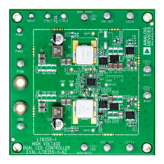
Page 2: Board Photo
DEMO MANUAL EVAL-LT8355-1-AZ BOARD PHOTO eval-lt8355-1-az Figure 1. EVAL-LT8355-1-AZ Demo Board PERFORMANCE SUMMARY Specifications are at T = 25°C PARAMETER CONDITION UNITS Input Voltage PVIN Range Operating Switching Frequency (f , 100% to 125% SSFM) R40 = 86.6k 8V < PVIN < 18V, CTRL1, CTRL2, ADJ2 Turrets = Float CH1: RS2 = 0.56Ω, V... -
Page 3: Quick Start Procedure
DEMO MANUAL EVAL-LT8355-1-AZ QUICK START PROCEDURE Evaluation board EVAL-LT8355-1-AZ is easy to set up 5. To change the brightness with analog dimming, the to evaluate the performance of the LT8355-1. Follow the CTRL1 pin is used for channel 1 and CTRL2 and IADJ2 procedure below. - Page 4 DEMO MANUAL EVAL-LT8355-1-AZ QUICK START PROCEDURE eval-lt8355-1-az F02 Figure 2. Setup Drawing for EVAL-LT8355-1-AZ: Channel 1 as Boost LED Driver, and Channel 2 as Buck-Boost Mode LED Driver (See Boost LED Driver Setup Section for More Information on Boost Topology) Rev. 0...
- Page 5 = V + 120µA • R1 LED_OVP BOOST LED DRIVER SETUP EVAL-LT8355-1-AZ has channel 1 assembled as a boost To configure EVAL-LT8355-1-AZ channel 2 as a boost LED driver and channel 2 as a buck-boost mode LED LED driver, remove R53, R52, Q2, FB10, C38 and C49.
- Page 6 Channel 1, 72V 450mA, Channel 2, 30V 50V/DIV LED1 1A/DIV 50V/DIV LED2 1A/DIV eval-lt8355-1-az F05 2ms/DIV Figure 5. EVAL-LT8355-1-AZ, Internal 250Hz 10% PWM Dimming with EMI Filters: 12V , Channel 1, 72V 450mA, Channel 2, 30V LED1 500mA/DIV LED2 1A/DIV eval-lt8355-1-az F06 2µs/DIV...
-
Page 7: Test Results
LED2 500mA/DIV eval-lt8355-1-az F07 200µs/DIV = 250kHz 100% TO 125% SSFM Figure 7. EVAL-LT8355-1-AZ: 50% to 100% to 50% Load Step Transient Response, 12V eval-lt8355-1-az Figure 8. EVAL-LT8355-1-AZ, Thermal Image with EMI Filters: , Channel 1, 72V 450mA, Channel 2, 30V Rev. 0... - Page 8 DEMO MANUAL EVAL-LT8355-1-AZ TEST RESULTS CLASS 5 PEAK LIMIT CLASS 5 AVERAGE LIMIT EVAL-LT8355-1-AZ EVAL-LT8355-1-AZ EVAL-LT8355-1-AZ WITH SHIELD EVAL-LT8355-1-AZ WITH SHIELD AMBIENT AMBIENT –10 –10 –20 –20 FREQUENCY (MHz) FREQUENCY (MHz) eval-lt8355-1-az F09b eval-lt8355-1-az F09a (a) CISPR25 Peak (b) CISPR25 Average Figure 9.
- Page 9 61.5mm metal shield. Part number for an example shield removable clip shield. can be found in the Parts List section in the Optional EMI eval-lt8355-1-az F12 Figure 12. EVAL-LT8355-1-AZ Top Silkscreen Outlining Placement of Shield Clips and EMI Shield on PCB Rev. 0...
- Page 10 DEMO MANUAL EVAL-LT8355-1-AZ PARTS LIST ITEM REFERENCE PART DESCRIPTION MANUFACTURER/PART NUMBER Required Circuit Components C3, C29 CAP ., 100μF, ALUM ELECT, 25V, 20%, 6.3mm × 7.7mm, PANASONIC, EEEHAE101XAP D8, SMD, RADIAL, EEEHA, AEC-Q200 CAP ., 1μF, X7R, 25V, 10%, 0805, AEC-Q200 TDK, CGA4J3X7R1E105K125AB CAP ., 1000pF, X7R, 50V, 10%, 0402, AEC-Q200...
-
Page 11: Parts List
DEMO MANUAL EVAL-LT8355-1-AZ PARTS LIST ITEM REFERENCE PART DESCRIPTION MANUFACTURER/PART NUMBER Optional EMI Filter Components C1, C27 CAP ., OPTION, 0402 C2, C28 CAP ., OPTION, 1206 C5, C6, C30, C45 CAP ., 10μF, X7R, 25V, 10%, 1210, AEC-Q200 TDK, CGA6P1X7R1E106K250AC C15, C43 CAP ., 0.1μF, X7S, 100V, 10%, 0603, AEC-Q200... - Page 12 DEMO MANUAL EVAL-LT8355-1-AZ SCHEMATIC DIAGRAM Rev. 0...
-
Page 13: Schematic Diagram
Devices for its use, nor for any infringements of patents or other rights of third parties that may result from its use. Specifications subject to change without notice. No license is granted by implication or otherwise under any patent or patent rights of Analog Devices. - Page 14 Board until you have read and agreed to the Agreement. Your use of the Evaluation Board shall signify your acceptance of the Agreement. This Agreement is made by and between you (“Customer”) and Analog Devices, Inc. (“ADI”), with its principal place of business at One Technology Way, Norwood, MA 02062, USA. Subject to the terms and conditions of the Agreement, ADI hereby grants to Customer a free, limited, personal, temporary, non-exclusive, non-sublicensable, non-transferable license to use the Evaluation Board FOR EVALUATION PURPOSES ONLY.
Need help?
Do you have a question about the EVAL-LT8355-1-AZ and is the answer not in the manual?
Questions and answers