Table of Contents
Advertisement
Advertisement
Table of Contents

Related Manuals for ToupTek SWIR1300KMA


Summary of Contents for ToupTek SWIR1300KMA
- Page 1 User Manual for Machine Vision Cameras...
-
Page 2: Table Of Contents
I3CMOS series camera specifications(Monochromatic, GS or RS,9) ..............8 SWIR series camera specification ..........................9 Application of SWIR camera ..........................9 SWIR1300KMA Specification ..........................10 SWIR330KMA Specification ..........................12 Packing list of SWIR series camera ........................14 IUA series technical specifications..........................15 IUA390KMA................................ - Page 3 User Manual for Machine Vision Cameras 3.24 IUA20400KPA ..............................38 3.25 IUA45000KMA ..............................39 3.26 IUA2100KPA(NIR) ............................40 3.27 IUA4100KPA(NIR) ............................41 3.28 IUA1300KMA(GPixel UV) ..........................42 3.29 IUA4200KMA(GPixel NIR) ..........................43 3.30 IUA4200KMB(GPixel UV) ..........................44 3.31 IUA4200KME(GPixel UV) ..........................45 3.32 IUA8000KMA(GS-UV) ...........................
- Page 4 User Manual for Machine Vision Cameras SWIR series camera dimensions .......................... 74 IUA series camera dimensions and outputs ......................75 8.2.1 IUA series camera mechanical housing dimensions ..................75 8.2.2 IUA series camera interface .......................... 75 8.2.3 IUA series camera power supply and I/O connector ..................76 8.2.4 IUA series camera packing information ......................
- Page 5 User Manual for Machine Vision Cameras 11.4.2 Trigger mode ..............................95 11.4.3 Trigger signal source selection........................95 11.4.4 Frame burst mode ............................97 11.4.5 Counter trigger mode ............................ 98 11.4.6 PWM trigger mode ............................99 11.5 General Purpose I/O configuration ......................... 100 11.6 Input signal ..............................
-
Page 6: Introduction To Toupcam Machine Vision Cameras
1.3 SWIR series camera specifications(SWIR, 2) Model Number Image Sensor Pixel Size(μm) G Sensitivity/Dark Signal FPS/Resolution Binning Exposure Time 1.3M/IMX990(M) 121mV with 1/30s 132@1280x1024 SWIR1300KMA 5 x5 50us~60s 1/2”(6.40x5.12) 1.0mV with 1/30s 253@640x512 0.33M/IMX991(M) 121mV with 1/30s 258.8@640x512 SWIR330KMA 5 x5 50us~60s 1/4”(3.20x2.56) - Page 7 User Manual for Machine Vision Cameras Time 0.4M/IMX287LLR(M,GS) 7320mv with 1/30s IUA390KMA 6.9x6.9 101.5fps@720×540 6us~15s 1/2.9“ (4.97x3.73) 0.76mv with 1/30s 0.5M/IMX426LLJ(M,GS) 8100mv with 1/30s IUA503KMA 9.0x9.0 79.8fps@800×620 6us~15s 1/1.7“ (7.2x5.58) 0.3mv with 1/30s 0.5M/IMX433LLJ(M,GS) 8100mv with 1/30s IUA503KMB 9.0x9.0 79.8fps@800×620 6us~15s 1/1.7“...
-
Page 8: Iub Series Camera Specifications(End Of Life, Not Recommended 3)
User Manual for Machine Vision Cameras 4.2M/GSENSE2020BSI 1.1x10⁸(e-/((W/m2).s)) IUA4200KMB 32fps@2048×2048 (M,UV,RS) 6.5x6.5 QE93.7%@550nm 21us~60s (GPixel UV) 32fps@1024×1024 1.2“(13.31x13.31) 80(e-/s/pix) 3.25x10⁸(e-/((W/m2).s)) IUA4200KME 4.2M/GSENSE400BSI(M,UV,RS) 37fps@2048×2048 11.0x11.0 QE95.3%@560nm 21us~60s (GPixel UV) 2.0“(22.53x22.53) 37fps@1024×1024 345(e-/s/pix) IUA8000KMA 8.0M/IMX487-AAMJ(M,UV,GS) 145mv with 1/30s 45fps@2840×2840 2.74x2.74 30us~15s (GS-UV) 2/3“... -
Page 9: I3Cmos Series Camera Specifications(Monochromatic, Gs Or Rs,9)
User Manual for Machine Vision Cameras I3ISPM05000KPB 5.0M/IMX264LQR(C, GS) 1146mv with 1/30s 35.6fps@2448×1536, 3.45×3.45 15us~15s IP805000B 2/3”(8.45x7.07) 0.15mv with 1/30s 87.6fps@1224×1024 I3ISPM06300KPA 6.3M/IMX178LQJ(C, RS) 425mv with 1/30s 58.7fps@3072×2048 2.4x2.4 17us~15s IP806300A 1/1.8“ (7.37x4.92) 0.15mv with 1/30s 59.5fps@1536×1024 1.8 I3CMOS series camera specifications(Monochromatic, GS or RS,9) G Sensitivity/Dark Exposure Model Number... -
Page 10: Swir Series Camera Specification
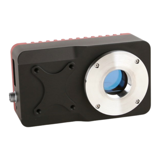
User Manual for Machine Vision Cameras 2 SWIR series camera specification 2.1 Application of SWIR camera SWIR series are TE-Cooling USB3.0 InGaAs SWIR cameras,which adopts Sony IMX990 / IMX991 Short-Wavelength Infrared (SWlR) Image Sensor. It is suitable to capture images in both visible range and SWlR range, covering 400nm to 1700nm. -
Page 11: Swir1300Kma Specification
Power with USB3.0 or 12V Power adapter Power consumption <2.1W(without cooling) / <25W(cooling) Temperature Working temperature -20~60℃, storage temperature -40~85℃ Humidity 20%-80%, no condensation Size 80mm×80mm×45.5mm Weight 380g Lens mount C-mount Software ToupView/ SDK Operating system Win32/WinRT/Linux/macOS/Android Certification CE, FCC Table 2-1 SWIR1300KMA camera specifications... - Page 12 User Manual for Machine Vision Cameras 图 2-1 SWIR1300KMA spectral response curve 图 2-2 SWIR1300KMA relative quantum efficiency 图 2-3 SWIR1300KMA absolute quantum efficiency...
-
Page 13: Swir330Kma Specification
User Manual for Machine Vision Cameras 2.3 SWIR330KMA Specification G Sensitivity/Dark Model Number Image Sensor Pixel Size(μm) FPS/Resolution Binning Exposure Time Signal 0.33M/IMX991(M) 121mV with 1/30s 258.8@640x512 SWIR330KMA 5 x5 50us~60s 1/4”(3.20x2.56) 1.0mV with 1/30s 486.1@320x256 SWIR330KMA Model Parameter 0.33M pixels 1/4” CMOS USB3.0 industrial camera Camera Sensor model Sony IMX991-AABA-C... - Page 14 User Manual for Machine Vision Cameras 图 2-4 SWIR330KMA spectral response curve 图 2-5 SWIR330KMA relative quantum efficiency 图 2-6 SWIR330KMA absolute quantum efficiency...
-
Page 15: Packing List Of Swir Series Camera
User Manual for Machine Vision Cameras 2.4 Packing list of SWIR series camera Standard Package 3-A safety equipment case: L:28cm W:23cm H:15.5cm (1pcs, 2.8Kg/ box); Carton size: L:28.2cm W:25.2cm H:16.7cm(TBD) One SWIR series camera(C-mount) D1, D2, D3 and D4 are national standard, American Standard, European standard, and British standard power lines respectively Power adapter: input: AC 100~240V 50Hz/60Hz, output: DC12 V 3A High-Speed USB3.0 A male to B male gold-plated connectors cable /1.5m One external trigger control cable... -
Page 16: Iua Series Technical Specifications
User Manual for Machine Vision Cameras 3 IUA series technical specifications 3.1 IUA390KMA Model IUA390KMA Parameter 0.39M pixel 1/2.9 "CMOS USB3.0 industrial camera Camera Sensor model Sony IMX287LLR Pixel size 6.9 µm x 6.9 µm Sensor size 1/2.9” Frame rate 101.5fps@720 x 540 Dynamic range 76.5dB... -
Page 17: Iua503Kma
User Manual for Machine Vision Cameras 3.2 IUA503KMA Model IUA503KMA Parameter 0.5M pixel 1/1.7 "CMOS USB3.0 industrial camera Camera Sensor model Sony IMX426LLJ Pixel size 9.0 µm x 9.0 µm Sensor size 1/1.7” Frame rate 79.8fps@800 x 620 Dynamic range 72.3dB Signal-to-Noise ratio 50.0dB... -
Page 18: Iua503Kmb
User Manual for Machine Vision Cameras 3.3 IUA503KMB Model IUA503KMB Parameter 0.5M pixel 1/1.7 "CMOS USB3.0 industrial camera Camera Sensor model Sony IMX433LLJ Pixel size 9.0 µm x 9.0 µm Sensor size 1/1.7” Frame rate 79.8fps@800 x 620 Dynamic range 72.3dB Signal-to-Noise ratio 50.0dB... -
Page 19: Iua1500Kma
User Manual for Machine Vision Cameras 3.4 IUA1500KMA Model IUA1500KMA Parameter 1.5M pixels 1/2.9” CMOS USB3.0 industrial camera Camera Sensor model Sony IMX273LLR Pixel size 3.45 µm×3.45 µm Sensor size 1/2.9” Frame rate 155fps@1440×1080,523fps@720×540 Dynamic range 73.6dB Signal-to-Noise ratio 40.4dB Sensitivity 71%@575nm Peak QE... -
Page 20: Iua1500Kpa
User Manual for Machine Vision Cameras 3.5 IUA1500KPA Model IUA1500KPA Parameter 1.5M pixels 1/2.9” CMOS USB3.0 industrial camera Camera Sensor model Sony IMX273LQR Pixel size 3.45 µm×3.45 µm Sensor size 1/2.9” Frame rate 155fps@1440×1080,523fps@720×540 Dynamic range 73.6dB Signal-to-Noise ratio 40.4dB Sensitivity 1146mV Dark current... -
Page 21: Iua1700Kma
User Manual for Machine Vision Cameras 3.6 IUA1700KMA Model IUA1700KMA Parameter 1.7M pixel 1.1 "CMOS USB3.0 industrial camera Camera Sensor model Sony IMX432LLJ Pixel size 9.0 µm x 9.0 µm Sensor size 1.1” Frame rate 98.6fps@1600 x 1100 Dynamic range 72.3dB Signal-to-Noise ratio 50.0dB... -
Page 22: Iua1700Kpa
User Manual for Machine Vision Cameras 3.7 IUA1700KPA IUA1700KPA Model Parameter 1.7M pixels 1.1” CMOS USB3.0 industrial camera Camera Sensor model Sony IMX432LQJ Pixel size 9.0 µm x 9.0 µm Sensor size 1.1” Frame rate 98.6fps@1600 x 1100 Dynamic range 72.3dB Signal-to-Noise ratio 50.0dB... -
Page 23: Iua2300Kma
User Manual for Machine Vision Cameras 3.8 IUA2300KMA IUA2300KMA Model Parameter 2.3M pixels 1/1.2” CMOS USB3.0 industrial camera Camera Sensor model Sony IMX174LLJ Pixel size 5.86 µm x 5.86 µm Sensor size 1/1.2” Frame rate 164.5fps@1920 x 1200 Dynamic range 73.6dB Signal-to-Noise ratio 44.8dB... -
Page 24: Iua2300Kpa
User Manual for Machine Vision Cameras 3.9 IUA2300KPA IUA2300KPA Model Parameter 2.3M pixels 1/1.2” CMOS USB3.0 industrial camera Camera Sensor model Sony IMX174LQJ Pixel size 5.86 µm x 5.86 µm Sensor size 1/1.2” Frame rate 164.5fps@1920 x 1200 Dynamic range 73.6dB Signal-to-Noise ratio 44.8dB... -
Page 25: Iua2300Kmb
User Manual for Machine Vision Cameras 3.10 IUA2300KMB IUA2300KMB Model Parameter 2.3M pixels 1/1.2” CMOS USB3.0 industrial camera Camera Sensor model Sony IMX249LLJ Pixel size 5.86 µm x 5.86 µm Sensor size 1/1.2” Frame rate 30fps@1920 x 1200 Dynamic range 73.6dB Signal-to-Noise ratio 44.8dB... -
Page 26: Iua2300Kpb
User Manual for Machine Vision Cameras 3.11 IUA2300KPB IUA2300KPB Model Parameter 2.3M pixels 1/1.2” CMOS USB3.0 industrial camera Camera Sensor model Sony IMX249LQJ Pixel size 5.86 µm x 5.86 µm Sensor size 1/1.2” Frame rate 30fps@1920 x 1200 Dynamic range 73.6dB Signal-to-Noise ratio 44.8dB... -
Page 27: Iua2800Kma
User Manual for Machine Vision Cameras 3.12 IUA2800KMA IUA2800KMA Model Parameter 2.8M pixels 2/3” CMOS USB3.0 industrial camera Camera Sensor model Sony IMX421LLJ Pixel size 4.5 µm x4.5 µm Sensor size 2/3” Frame rate 121fps@1936×1464,425fps@968×732 Dynamic range 72.3dB Signal-to-Noise ratio 44.0dB Peak QE 78%@575nm... -
Page 28: Iua2800Kpa
User Manual for Machine Vision Cameras 3.13 IUA2800KPA IUA2800KPA Model Parameter 2.8M pixels 2/3” CMOS USB3.0 industrial camera Camera Sensor model Sony IMX421LQJ Pixel size 4.5 µm x4.5 µm Sensor size 2/3” Frame rate 121fps@1936×1464,425fps@968×732 Dynamic range 72.3dB Signal-to-Noise ratio 44.0dB Peak QE 78%@575nm... -
Page 29: Iua5000Kma
User Manual for Machine Vision Cameras 3.14 IUA5000KMA Model IUA5000KMA Parameter 5.0M pixels 2/3” CMOS USB3.0 industrial camera Camera Sensor model Sony IMX264LLR Pixel size 3.45 µm×3.45 µm Sensor size 2/3” Frame rate 35.6fps@2448×2048、87.6fps@1224×1024 Dynamic range 73.6dB Signal-to-Noise ratio 40.4dB Sensitivity 71%@575nm Peak QE... -
Page 30: Iua5000Kpa
User Manual for Machine Vision Cameras 3.15 IUA5000KPA Model IUA5000KPA Parameter 5.0M pixels 2/3” CMOS USB3.0 industrial camera Camera Sensor model Sony IMX264LQR Pixel size 3.45 µm×3.45 µm Sensor size 2/3” Frame rate 35.6fps@2448×2048、87.6fps@1224×1024 Dynamic range 73.6dB Signal-to-Noise ratio 40.4dB Sensitivity 1146mV Dark current... -
Page 31: Iua6300Kma
User Manual for Machine Vision Cameras 3.16 IUA6300KMA IUA6300KMA Model Parameter 6.3M pixels 1/1.8” CMOS USB3.0 industrial camera Camera Sensor model Sony IMX178LLJ Pixel size 2.4 µm x 2.4 µm Sensor size 1/1.8” Frame rate 59.9fps@3072 x 2048, 59.9fps@1536 x 1024 Dynamic range 71dB Signal-to-Noise ratio... -
Page 32: Iua6300Kpa
User Manual for Machine Vision Cameras 3.17 IUA6300KPA IUA6300KPA Model Parameter 6.3M pixels 1/1.8” CMOS USB3.0 industrial camera Camera Sensor model Sony IMX178LQJ Pixel size 2.4 µm x 2.4 µm Sensor size 1/1.8” Frame rate 59.8fps@3072 x 2048, 59.5fps@1536 x 1024 Dynamic range 75dB Signal-to-Noise ratio... -
Page 33: Iua7100Kma
User Manual for Machine Vision Cameras 3.18 IUA7100KMA IUA7100KMA Model Parameter 7.1M pixels 1.1” CMOS USB3.0 industrial camera Camera Sensor model Sony IMX428LLJ Pixel size 4.5 µm x 4.5 µm Sensor size 1.1” Frame rate 51.3fps@3200 x 2200, 133.8fps@1584 x 1100 Dynamic range 72.3dB Signal-to-Noise ratio... -
Page 34: Iua7100Kpa
User Manual for Machine Vision Cameras 3.19 IUA7100KPA IUA7100KPA Model Parameter 7.1M pixels 1.1” CMOS USB3.0 industrial camera Camera Sensor model Sony IMX428LQJ Pixel size 4.5 µm x 4.5 µm Sensor size 1.1” Frame rate 51.4fps@3200 x 2200, 133.8fps@1584 x 1100 Dynamic range 72.3dB Signal-to-Noise ratio... -
Page 35: Iua8300Kpa
User Manual for Machine Vision Cameras 3.20 IUA8300KPA IUA8300KPA Model Parameter 8.3M pixels 1/1.2” CMOS USB3.0industrial camera Camera Sensor model Sony IMX485LQJ-C Pixel size 2.9 µm x 2.9 µm Sensor size 1/1.2” Frame rate 45fps@3840 x2160、70fps@1920 x 1080 Dynamic range 70dB Signal-to-Noise ratio 43dB... -
Page 36: Iua20000Kma
User Manual for Machine Vision Cameras 3.21 IUA20000KMA Model IUA20000KMA Parameter 20.0M 1” CMOS USB3.0 industrial camera Camera Sensor model Sony IMX183CLK Pixel size 2.4 µm x 2.4 µm Sensor size 1” Frame rate 19.0fps@5440 x 3684, 49.9fps@2736 x 1824, 59.5fps@1824 x 1216 Dynamic range 71dB Signal-to-Noise ratio... -
Page 37: Iua20000Kpa
User Manual for Machine Vision Cameras 3.22 IUA20000KPA IUA20000KPA Model Parameter 20.0M pixels 1” CMOS USB3.0industrial camera Camera Sensor model Sony IMX183CQK Pixel size 2.4 µm x 2.4 µm Sensor size 1” Frame rate 19.0fps@5440 x 3684,48.8fps@2736 x 1824,59.4fps@1824 x 1216 Dynamic range 71dB Signal-to-Noise ratio... -
Page 38: Iua20400Kma
User Manual for Machine Vision Cameras 3.23 IUA20400KMA IUA20400KMA Model Parameter 20.4M pixels 1.1” CMOS USB3.0 industrial camera Camera Sensor model Sony IMX541-AAMJ-C Pixel size 2.74 µm x2.74 µm Sensor size 1.1” Frame rate 17.5fps@4496×4496,64.4fps@2240×2240,64.4fps@1120×1120 Dynamic range 72.0dB Signal-to-Noise ratio 40.0dB Peak QE 86%@520nm... -
Page 39: Iua20400Kpa
User Manual for Machine Vision Cameras 3.24 IUA20400KPA IUA20400KPA Model Parameter 20.4M pixels 1.1” CMOS USB3.0 industrial camera Camera Sensor model Sony IMX541-AAQJ-C Pixel size 2.74 µm x2.74 µm Sensor size 1.1” Frame rate 17.5fps@4496×4496,64.4fps@2240×2240,64.4fps@1120×1120 Dynamic range 72.0dB Signal-to-Noise ratio 40.0dB Sensitivity 1574mV... -
Page 40: Iua45000Kma
User Manual for Machine Vision Cameras 3.25 IUA45000KMA Model IUA45000KMA Parameter 45.0M 4/3” CMOS USB3.0 industrial camera Camera Sensor model Sony IMX492LLJ-C Pixel size 2.315 µm x 2.315 µm Sensor size 4/3” Frame rate 8.1@8176x5616(3:2),30.0@4080x2808(3:2) 8.1@7408x5556(4:3),33.0@3696x2778(4:3) 10.4@8176x4320(17:9),34.7@4096x2160(17:9),62.5@2048x1080(17:9),86.5@1360x720(17:9) Dynamic range 78.8dB Signal-to-Noise ratio 48.2dB Sensitivity... -
Page 41: Iua2100Kpa(Nir)
User Manual for Machine Vision Cameras 3.26 IUA2100KPA(NIR) IUA2100KPA Model Parameter 2.1M pixels 1/2.8” CMOS USB3.0 industrial camera Camera Sensor model Sony IMX462LQR Pixel size 2.9 µm x 2.9 µm Sensor size 1/2.8” Frame rate 120.3fps@1920 x 1080 Dynamic range 71dB Signal-to-Noise ratio 40dB... -
Page 42: Iua4100Kpa(Nir)
User Manual for Machine Vision Cameras 3.27 IUA4100KPA(NIR) IUA4100KPA Model Parameter 4.1M pixels 1/1.8” CMOS USB3.0 industrial camera Camera Sensor model Sony IMX464LQR Pixel size 2.9 µm x 2.9 µm Sensor size 1/1.8” Frame rate 90fps@2688 x 1520 Dynamic range 71dB Signal-to-Noise ratio 40dB... -
Page 43: Iua1300Kma(Gpixel Uv)
User Manual for Machine Vision Cameras 3.28 IUA1300KMA(GPixel UV) Model IUA1300KMA Parameter 1.3M pixels 1” CMOS USB3.0 industrial camera Camera Sensor model GPixel GLUX9701BSI (UV) Pixel size 9.76 µm x 9.76 µm Sensor size 1” Frame rate 30fps@1280 x 1024、30fps@640 x 512 Dynamic range 55dB(LG)、66dB(HG)、89.5dB(HDR)... -
Page 44: Iua4200Kma(Gpixel Nir)
User Manual for Machine Vision Cameras 3.29 IUA4200KMA(GPixel NIR) Model IUA4200KMA Parameter 4.2M pixels 1.2” CMOS USB3.0 industrial camera Camera Sensor model GPixel GSENSE2020e (NIR) Pixel size 6.5 µm x 6.5 µm Sensor size 1.2” Frame rate 45fps@2048 x 2048、45fps@1024 x 1024 Dynamic range 66.6dB(LG)、59.5dB(HG)、87.5dB(HDR)... -
Page 45: Iua4200Kmb(Gpixel Uv)
User Manual for Machine Vision Cameras 3.30 IUA4200KMB(GPixel UV) Model IUA4200KMB Parameter 4.2M pixels 1.2” CMOS USB3.0 industrial camera Camera Sensor model Gpixel GSENSE2020BSI -H (UV) Pixel size 6.5 µm x 6.5 µm Sensor size 1.2” Frame rate 32fps@2048 x 2048、32fps@1024 x 1024 Dynamic range 67.5dB(LG), 61dB(HG), 90.5dB(HDR) Signal-to-Noise ratio... -
Page 46: Iua4200Kme(Gpixel Uv)
User Manual for Machine Vision Cameras 3.31 IUA4200KME(GPixel UV) Model IUA4200KME Parameter 4.2M pixels 2.0” CMOS USB3.0 industrial camera Camera Sensor model Gpixel GSENSE400BSI (UV) Pixel size 11 µm x 11 µm Sensor size 2.0” Frame rate 37fps@2048 x 2048、37fps@1024 x 1024 Dynamic range 64dB(LG), 68.5dB(HG), 94dB(HDR) Signal-to-Noise ratio... -
Page 47: Iua8000Kma(Gs-Uv)
User Manual for Machine Vision Cameras 3.32 IUA8000KMA(GS-UV) IUA8000KMA Model Parameter 8.0M pixels 2/3” CMOS USB3.0 industrial camera Camera Sensor model Sony IMX487-AAMJ-C Pixel size 2.74 µm x2.74 µm Sensor size 2/3” Frame rate 45fps@2840×2840,198fps@1420×1420 Dynamic range 72.0dB Signal-to-Noise ratio 40.0dB Peak QE Sensitivity... -
Page 48: Iub Series Technical Specifications
User Manual for Machine Vision Cameras 4 IUB series technical specifications 4.1 IUB4200KMA IUB4200KMA Model Parameter 4.2M pixels 1.2” CMOS USB3.0 industrial camera Camera Sensor model GSENSE2020e Pixel size 6.5 µm x 6.5 µm Sensor size 1.2” Frame rate 45fps@2048 x 2046, 45fps@1024 x 1022 Dynamic range 66.6dB (LG), 59.5dB (HG), 87.5dB (HDR) Signal-to-Noise ratio... -
Page 49: Iub4200Kmb
User Manual for Machine Vision Cameras 4.2 IUB4200KMB IUB4200KMB Model Parameter 4.2M pixels 1.2” CMOS USB3.0 industrial camera Camera Sensor model GSENSE2020BSI Pixel size 6.5 µm x 6.5 µm Sensor size 1.2” Frame rate 43.6fps@2048 x 2046, 43.6fps@1024 x 1022 Dynamic range 67.5dB (LG), 61dB (HG), 90.7dB (HDR) Signal-to-Noise ratio... -
Page 50: Iub43000Kma
User Manual for Machine Vision Cameras 4.3 IUB43000KMA IUB43000KMA Model Parameter 43.0M pixels 1.7” (APS-C) CMOS USB3.0 industrial camera Camera Sensor model GMAX0806 Pixel size 2.8 µm x 2.8 µm Sensor size 1.7’’ (APS-C) Frame rate 8.5fps@7904x5432 Dynamic range 66dB (2G), 63dB (6G) Signal-to-Noise ratio 38.5dB (2G), 34dB (6G) Sensitivity... -
Page 51: Iuc Series Technical Specifications
User Manual for Machine Vision Cameras 5 IUC series technical specifications 5.1 IUC26000KMA IUC26000KMA Model Parameter 26.0M pixels 1.8” (APS-C) CMOS USB3.0 industrial camera Camera Sensor model Sony IMX571BLR Pixel size 3.76 µm x 3.76 µm Sensor size 1.8’’ (APS-C) Frame rate 14fps@6224 x 4168(16bit), 37fps@3104 x 2084, 110fps@2064 x 1388 Dynamic range... -
Page 52: Iuc26000Kpa
User Manual for Machine Vision Cameras 5.2 IUC26000KPA IUC26000KPA Model Parameter 26.0M pixels 1.8” (APS-C) CMOS USB3.0 industrial camera Camera Sensor model Sony IMX571BQR Pixel size 3.76 µm x 3.76 µm Sensor size 1.8’’ (APS-C) Frame rate 14fps@6224 x 4168(16bit), 37fps@3104 x 2084, 110fps@2064 x 1388 Dynamic range 86.8dB Signal-to-Noise ratio... -
Page 53: Iuc31000Kma
User Manual for Machine Vision Cameras 5.3 IUC31000KMA IUC31000KMA Model Parameter 31.0M pixels 1.8” (APS-C) CMOS USB3.0 industrial camera Camera Sensor model Sony IMX342LLA Pixel size 3.45 µm x 3.45 µm Sensor size 1.8’’ (APS-C) Frame rate 12.0fps@6464 x 4852, 45.9fps@3216 x 2426 Dynamic range 73.6dB Signal-to-Noise ratio... -
Page 54: Iuc31000Kpa
User Manual for Machine Vision Cameras 5.4 IUC31000KPA IUC31000KPA Model Parameter 31.0M pixels 1.8” (APS-C) CMOS USB3.0 industrial camera Camera Sensor model Sony IMX342LQA Pixel size 3.45 µm x 3.45 µm Sensor size 1.8’’ (APS-C) Frame rate 12.0fps@6464 x 4852, 45.9fps@3216 x 2426 Dynamic range 73.6dB Signal-to-Noise ratio... -
Page 55: Iuc60000Kma
User Manual for Machine Vision Cameras 5.5 IUC60000KMA IUC60000KMA Model Parameter 60.0M pixels 2.7” (Full Frame) CMOS USB3.0 industrial camera Camera Sensor model Sony IMX455ALK Pixel size 3.76 µm x 3.76 µm Sensor size 2.7’’ (Full Frame) Frame rate 6.1fps@9568 x 6380(16bit), 24.6fps@4784 x 3190, 55.8fps@3184 x 2124, 191.0@1040 x 706 Dynamic range 88.3dB Signal-to-Noise ratio... -
Page 56: Iuc60000Kpa
User Manual for Machine Vision Cameras 5.6 IUC60000KPA IUC60000KPA Model Parameter 60.0M pixels 2.7” (Full Frame) CMOS USB3.0 industrial camera Camera Sensor model Sony IMX455AQK Pixel size 3.76 µm x 3.76 µm Sensor size 2.7’’ (Full Frame) Frame rate 6.1fps@9568 x 6380(16bit), 24.6fps@4784 x 3190, 55.8fps@3184 x 2124, 191.0@1040 x 706 Dynamic range 85.8dB Signal-to-Noise ratio... -
Page 57: I3Ispm Series Technical Specifications
User Manual for Machine Vision Cameras 6 I3ISPM series technical specifications 6.1 I3ISPM00500KPA Model I3ISPM00500KPA Parameter 0.5M 1/1.7” CMOS USB3.0 industrial camera Camera Sensor model Sony IMX433LQJ Pixel size 9.0 µm×9.0 µm Sensor size 1/1.7” Frame rate 166.5fps@812×620 Dynamic range 72.3dB Signal-to-Noise ratio 50.0dB... -
Page 58: I3Ispm01500Kpa
User Manual for Machine Vision Cameras 6.2 I3ISPM01500KPA I3ISPM01500KPA Model Parameter 1.5M pixels 1/2.9” CMOS USB3.0industrial camera Camera Sensor model Sony IMX273LQR Pixel size 3.45 µm×3.45 µm Sensor size 1/2.9” Frame rate 227.2fps@1440×1080,382.7fps@720×540 Dynamic range 73.6dB Signal-to-Noise ratio 40.4dB Sensitivity 1146mV Dark current 0.15mV... -
Page 59: I3Ispm02300Kpa
User Manual for Machine Vision Cameras 6.3 I3ISPM02300KPA I3ISPM02300KPA Model Parameter 2.3M pixels 1/1.2” CMOS USB3.0industrial camera Camera Sensor model Sony IMX174LQJ Pixel size 5.86 µm x 5.86 µm Sensor size 1/1.2” Frame rate 164.5fps@1920 x 1200 Dynamic range 73.6dB Signal-to-Noise ratio 44.8dB Sensitivity... -
Page 60: I3Ispm02300Kpb
User Manual for Machine Vision Cameras 6.4 I3ISPM02300KPB I3ISPM02300KPB Model Parameter 2.3M pixels 1/1.2” CMOS USB3.0industrial camera Camera Sensor model Sony IMX249LQJ Pixel size 5.86 µm x 5.86 µm Sensor size 1/1.2” Frame rate 30fps@1920 x 1200 Dynamic range 73.6dB Signal-to-Noise ratio 44.8dB Sensitivity... -
Page 61: I3Ispm03100Kpa
User Manual for Machine Vision Cameras 6.5 I3ISPM03100KPA I3ISPM03100KPA Model Parameter 3.1M pixels 1/1.8” CMOS USB3.0 industrial camera Camera Sensor model Sony IMX252LQR Pixel size 3.45 µm×3.45 µm Sensor size 1/1.8” Frame rate 115fps@2048×1536,230.3fps@1024×768 Dynamic range 73.6dB Signal-to-Noise ratio 40.4dB Sensitivity 1146mV Dark current... -
Page 62: I3Ispm03100Kpb
User Manual for Machine Vision Cameras 6.6 I3ISPM03100KPB I3ISPM03100KPB Model Parameter 3.1M pixels 1/1.8” CMOS USB3.0 industrial camera Camera Sensor model Sony IMX265LQR Pixel size 3.45 µm×3.45 µm Sensor size 1/1.8” Frame rate 55.4fps@2048×1536,115.1fps@1024×768 Dynamic range 73.6dB Signal-to-Noise ratio 40.4dB Sensitivity 1146mV Dark current... -
Page 63: I3Ispm05000Kpa
User Manual for Machine Vision Cameras 6.7 I3ISPM05000KPA I3ISPM05000KPA Model Parameter 5M pixels 2/3” CMOS USB3.0 industrial camera Camera Sensor model Sony IMX250LQR Pixel size 3.45 µm×3.45 µm Sensor size 2/3” Frame rate 71.2fps@2448×2048,175.2fps@1224×1024 Dynamic range 73.6dB Signal-to-Noise ratio 40.4dB Sensitivity 1146mV Dark current... -
Page 64: I3Ispm05000Kpb
User Manual for Machine Vision Cameras 6.8 I3ISPM05000KPB I3ISPM05000KPB Model Parameter 5M pixels 2/3” CMOS USB3.0 industrial camera Camera Sensor model Sony IMX264LQR Pixel size 3.45 µm×3.45 µm Sensor size 2/3” Frame rate 35.6fps@2448×2048, 87.6fps@1224×1024 Dynamic range 73.6dB Signal-to-Noise ratio 40.4dB Sensitivity 1146mV... -
Page 65: I3Ispm06300Kpa
User Manual for Machine Vision Cameras 6.9 I3ISPM06300KPA I3ISPM06300KPA Model Parameter 6.3M pixels 1/1.8” CMOS USB3.0 industrial camera Camera Sensor model Sony IMX178LQJ Pixel size 2.4 µm×2.4 µm Sensor size 1/1.8” Frame rate 58.7fps@3072×2048, 59.5fps@1536×1024 Dynamic range 71dB Signal-to-Noise ratio 40dB Sensitivity 425mV... -
Page 66: I3Cmos Series Technical Specifications
User Manual for Machine Vision Cameras 7 I3CMOS series technical specifications 7.1 I3CMOS00500KMA Model I3CMOS00500KMA Parameter 0.5M pixel 1 / 1.7 "CMOS USB3.0 industrial camera Camera Sensor model Sony IMX433LLJ Pixel size 9.0 µm×9.0 µm Sensor size 1/1.7” Frame rate 166.5fps@812×620 Dynamic range 72.3dB... -
Page 67: I3Cmos01500Kma
User Manual for Machine Vision Cameras 7.2 I3CMOS01500KMA I3CMOS01500KMA Model Parameter 1.5M pixels 1/2.9” CMOS USB3.0 industrial camera Camera Sensor model Sony IMX273LLR Pixel size 3.45 µm×3.45 µm Sensor size 1/2.9” Frame rate 226.5fps@1440×1080, 506fps@720×540 Dynamic range 73.6dB Signal-to-Noise ratio 40.4dB Peak QE 71%@575nm... -
Page 68: I3Cmos02300Kma
User Manual for Machine Vision Cameras 7.3 I3CMOS02300KMA I3CMOS02300KMA Model Parameter 2.3M pixels 1/1.2” CMOS USB3.0 industrial camera Camera Sensor model Sony IMX174LLJ Pixel size 5.86 µm x 5.86 µm Sensor size 1/1.2” Frame rate 164.5fps@1920 x 1200 Dynamic range 73.6dB Signal-to-Noise ratio 44.8dB... -
Page 69: I3Cmos02300Kmb
User Manual for Machine Vision Cameras 7.4 I3CMOS02300KMB I3CMOS02300KMB Model Parameter 2.3M pixels 1/1.2” CMOS USB3.0 industrial camera Camera Sensor model Sony IMX249LLJ Pixel size 5.86 µm x 5.86 µm Sensor size 1/1.2” Frame rate 30fps@1920 x 1200 Dynamic range 73.6dB Signal-to-Noise ratio 44.8dB... -
Page 70: I3Cmos03100Kma
User Manual for Machine Vision Cameras 7.5 I3CMOS03100KMA I3CMOS03100KMA Model Parameter 3.1M pixels 1/1.8” CMOS USB3.0 industrial camera Camera Sensor model Sony IMX252LLR Pixel size 3.45 µm×3.45 µm Sensor size 1/1.8” Frame rate 110.6fps@2048×1536, 233.8fps@1024×768 Dynamic range 73.6dB Signal-to-Noise ratio 40.4dB Peak QE 71%@575nm... -
Page 71: I3Cmos03100Kmb
User Manual for Machine Vision Cameras 7.6 I3CMOS03100KMB I3CMOS03100KMB Model Parameter 3.1M pixels 1/1.8” CMOS USB3.0 industrial camera Camera Sensor model Sony IMX265LLR Pixel size 3.45 µm×3.45 µm Sensor size 1/1.8” Frame rate 55.4fps@2048×1536,115.1fps@1024×768 Dynamic range 73.6dB Signal-to-Noise ratio 40.4dB Peak QE 71%@575nm Sensitivity... -
Page 72: I3Cmos05000Kma
User Manual for Machine Vision Cameras 7.7 I3CMOS05000KMA I3CMOS05000KMA Model Parameter 5M pixels 2/3” CMOS USB3.0 industrial camera Camera Sensor model Sony IMX250LLR Pixel size 3.45 µm×3.45 µm Sensor size 2/3” Frame rate 70.9fps@2448×2048, 175.2fps@1224×1024 Dynamic range 73.6dB Signal-to-Noise ratio 40.4dB Peak QE 71%@575nm... -
Page 73: I3Cmos05000Kmb
User Manual for Machine Vision Cameras 7.8 I3CMOS05000KMB I3CMOS05000KMB Model Parameter 5M pixels 2/3” CMOS USB3.0 industrial camera Camera Sensor model Sony IMX264LLR Pixel size 3.45 µm×3.45 µm Sensor size 2/3” Frame rate 35.6fps@2448×2048,87.6fps@1224×1024 Dynamic range 73.6dB Signal-to-Noise ratio 40.4dB Peak QE 71%@575nm Sensitivity... -
Page 74: I3Cmos06300Kma
User Manual for Machine Vision Cameras 7.9 I3CMOS06300KMA I3CMOS06300KMA Model Parameter 6.3M pixels 1/1.8” CMOS USB3.0 industrial camera Camera Sensor model Sony IMX178LLJ Pixel size 2.4 µm×2.4 µm Sensor size 1/1.8” Frame rate 58.7fps@3072×2048,59.5fps@1536×1024 Dynamic range 71dB Signal-to-Noise ratio 40dB Sensitivity 760mV Dark current... -
Page 75: Camera Dimension And Interface
User Manual for Machine Vision Cameras 8 Camera Dimension and Interface 8.1 SWIR series camera dimensions Figure 8-1 Dimension of SWIR series camera... -
Page 76: Iua Series Camera Dimensions And Outputs
User Manual for Machine Vision Cameras 8.2 IUA series camera dimensions and outputs 8.2.1 IUA series camera mechanical housing dimensions Figure 8-2 IUA series camera Figure 8-3 Dimensions of IUA camera housing (mm) Figure 8-4 Dimensions of IUA circuit board (mm) 8.2.2 IUA series camera interface The back of the industrial camera is shown in Figure 8-5. -
Page 77: Iua Series Camera Power Supply And I/O Connector
User Manual for Machine Vision Cameras Figure 8-5 Schematic diagram of IUA camera back panel 8.2.3 IUA series camera power supply and I/O connector The pin signal definition for the IUA series camera 7 Pin I/O connector is shown in Table 8-1. Color Signal Signal description... -
Page 78: Iub Series Camera Dimensions And Outputs
User Manual for Machine Vision Cameras 8.3 IUB series camera dimensions and outputs 8.3.1 IUB series camera mechanical housing dimensions Figure 8-6 IUB series camera Figure 8-7 Dimensions of IUB camera housing (mm) Figure 8-8 Dimensions of IUB circuit board (mm) -
Page 79: Iub Series Camera Interface
User Manual for Machine Vision Cameras 8.3.2 IUB series camera interface The back of the industrial camera is shown in Figure 8-9. It has standard USB3.0 output, 7 Pin I/O port (aviation head) and on/off indicator. It has two M2 screw holes on both sides of USB 3.0 port to fix the cable. The holes reduce cable loosening caused by field vibration. -
Page 80: Iuc Series Camera Dimensions And Outputs
User Manual for Machine Vision Cameras 8.4 IUC series camera dimensions and outputs 8.4.1 IUC series camera mechanical housing dimensions Figure 8-10 IUC series camera Figure 8-11 Dimensions of IUC camera housing (mm) Figure 8-12 Dimensions of IUC circuit board (mm) -
Page 81: Iuc Series Camera Interface
User Manual for Machine Vision Cameras 8.4.2 IUC series camera interface The back of the industrial camera is shown in Figure 8-13. It has standard USB3.0 output, 7 Pin I/O port (aviation head) and on/off indicator. It has two M2 screw holes on both sides of USB 3.0 port to fix the cable. The holes reduce cable loosening caused by field vibration. -
Page 82: I3Cmos And I3Ispm Series Camera Dimensions And Outputs
User Manual for Machine Vision Cameras 8.5 I3CMOS and I3ISPM series camera dimensions and outputs 8.5.1 I3CMOS and I3ISPM series camera mechanical housing dimensions Figure 8-14 I3CMOS or I3ISPM series camera Figure 8-15 Dimensions of camera housing(mm) -
Page 83: I3Cmos And I3Ispm Series Camera Interface
User Manual for Machine Vision Cameras Figure 8-16 Dimensions of circuit board(mm) 8.5.2 I3CMOS and I3ISPM series camera interface The back of the industrial camera is shown in Figure 8-17. It has standard USB3.0 output, 6 Pin I/O port (aviation head) and on/off indicator. - Page 84 User Manual for Machine Vision Cameras USB3.0 cable Suitable length of Micro USB3.0 cable Lens (optional) C-mount lens Table 8-9 Packing information and recommended accessories...
-
Page 85: Description Of Software Development
User Manual for Machine Vision Cameras Description of Software Development 9.1 SDK introduction The SDK download link is as follows: http: //www.touptek.com/download/showdownload.php?lang=en&id=32 9.1.1 SDK support platform ⚫ Win32: x86: XP SP3 and above versions; CPU needs to support the SSE2 instruction set at least... - Page 86 User Manual for Machine Vision Cameras toupcam.lib, arm lib file. toupcam.dll, arm dynamic library files. arm64: toupcam.lib, arm64 lib file. toupcam.dll, arm64 dynamic library files. winrt: They can be applied for Dynamic library files of WinRT/ UWP (Universal Windows Platform)/ Windows Store App.
-
Page 87: Client Democpp Description
User Manual for Machine Vision Cameras armel: libtoupcam.so, armel version so file, toolchain is arm-linux-gnueabi armhf: libtoupcam.so, armhf version so file, toolchain isarm-linux-gnueabihf arm64: libtoupcam.so, Arm64 version so file, toolchain is aarch64-linux-gnu ⚫ android: Android platform. libtoupcam.so. for the four architectures of arm, arm64, x86, x64 ⚫... -
Page 88: Toupview Ui Description
User Manual for Machine Vision Cameras Config: Set exposure, gain, white balance, frame rate, etc. 9.3 ToupView UI description ToupView software fully controls all camera features and streams high-speed videos by USB port using Ultra Fine color engine. Ultra Fine color engine contains excellent procedure of processing RAW data and thus realizes the conversion of sensor detected data to image. - Page 89 User Manual for Machine Vision Cameras enhancement morphology algorithm, image rotation, image scaling and image printing; Convenient and practical video and image size calibration, a variety of video and image two-dimensional geometric 2D measurement measurements such as length, area, perimeter and angle, etc., the measurement results can be controlled according to image characteristics or preferences;...
-
Page 90: Camera Installation And Operation
I3CMS05000KMB and then right-click the mouse button to see if the device drive is properly installed or not, as shown in Figure 10-1. Figure 10-1 ToupTek driver attribute Figure 10-2 Win USB driver attribute The operating systems above Windows 8(Including Windows 8) will install the driver automatically after the camera is connected and the driver name is USB3.0 Camera, as shown in Figure 10-2. - Page 91 User Manual for Machine Vision Cameras Figure 10-3 democpp UI...
-
Page 92: Main Features Of Democpp
User Manual for Machine Vision Cameras 11 Main Features of democpp 11.1 Description of main features As shown in Figure 11-1, in the democpp, click the "Resolution-> Preview" in the top control menu to select the resolution of the camera; "Resolution->Snap" captures image at current resolution; "Resolution->Snap Multiple" captures multiple images at the specified resolution. -
Page 93: Camera Data Format
User Manual for Machine Vision Cameras 11.2.1 Camera data format The list of pixel formats supported by the I3CMOS and I3ISPM series cameras are shown in Table 11-1. (“Y” for supported; “-” for not supported) Format RAW8 RAW10 RAW12 RAW14 RGB8 RGB24 RGB32... -
Page 94: Area Of Interest Setup
User Manual for Machine Vision Cameras Figure 11-2 Frame rate setup The following is the API code for the setup of the frame rate: Toupcam_put_Speed(HToupCam h, unsigned short nSpeed); 11.2.3 Area of interest setup When the user is only interested in some details of the image, the camera can output the image ROI according to the requirement. -
Page 95: Global Shutter And Rolling Shutter
User Manual for Machine Vision Cameras As shown in Figure 11-3, in democpp, click "Action->ROI" in the upper control menu and in "ROI" dialog, fill x Offset, y Offset, x Width, y Width to adjust the ROI, where the values in x Offset and y Offset represent the starting point of the ROI up left corner. -
Page 96: Image Acquisition And Transmission
User Manual for Machine Vision Cameras Figure 11-5 Rolling shutter exposure principle 11.4 Image acquisition and transmission There are two image acquisition modes, free run mode and trigger mode. Among them, the free run mode is continuous acquisition mode and the trigger mode captures one or more frames of images according to the trigger signal. The trigger sources include software trigger and external trigger. - Page 97 User Manual for Machine Vision Cameras Under the trigger mode, trigger signal source is either from software trigger, or from external trigger. The external trigger signal is from either the pin isolated by opto-coupler or the non-isolated pin. The following is the API code for the setup of the trigger source: // Trigger Source: 0->...
-
Page 98: Frame Burst Mode
User Manual for Machine Vision Cameras Figure 11-8 Set the external trigger source Figure 11-8 shows the configuration of external trigger. First select "Enter Trigger Mode" to enter trigger mode. Then click "IO Config" and the I/O Control dialog will pop up as shown in Figure 11-9. The trigger source is selected in the "Trigger Source"... -
Page 99: Counter Trigger Mode
User Manual for Machine Vision Cameras Trigger_in Trigger delay Sensor Sensor Sensor exposure1 exposure3 exposure2 Figure 11-10 Frame burst trigger timing Here is the API code for the setup of the trigger frame value Toupcam_IoControl(m_hCam, 0, TOUPCAM_IOCONTROLTYPE_SET_BURSTCOUNTER, val, NULL); 11.4.5 Counter trigger mode Under this mode, trigger signal number is divided by user-defined counter value. -
Page 100: Pwm Trigger Mode
User Manual for Machine Vision Cameras Toupcam_IoControl(m_hCam, 0, TOUPCAM_IOCONTROLTYPE_SET_TRIGGERSOURCE, 3, NULL); //Counter Source: 0-> line0 , 1-> line2 , 2-> line3 Toupcam_IoControl(m_hCam, 0, TOUPCAM_IOCONTROLTYPE_SET_COUNTERSOURCE, val, NULL); Toupcam_IoControl(m_hCam, 0, TOUPCAM_IOCONTROLTYPE_SET_COUNTERVALUE, val, NULL); 11.4.6 PWM trigger mode The camera provides Pulse Width Modulation (PWM) trigger mode, which controls exposure time by pulse width. The main difference between this mode and the standard single frame trigger mode is the exposure method. -
Page 101: General Purpose I/O Configuration
User Manual for Machine Vision Cameras Figure 11-14 PWM mode parameter control 11.5 General Purpose I/O configuration (This is for I3 series only)The camera with the hardware version number V2.0 and above has a configurable GPIO port, as shown in Figure 11-15, in the demo, enter the "IO Config" dialog, select the "Line Select" to be GPIO0 and then click the "GPIO Mode"... -
Page 102: Output Signal
User Manual for Machine Vision Cameras Figure 11-17 Signal Debounce setup The following is the API code for the setup of the debouncer time: Toupcam_IoControl(m_hCam, index, TOUPCAM_IOCONTROLTYPE_SET_DEBOUNCERTIME, val, NULL); 11.7 Output signal The camera provides 4 output signal modes: Frame Trigger Wait, Exposure Active, Strobe and User Output. As shown in Figure 11-18, in the "IO Config"... -
Page 103: Exposure Active
User Manual for Machine Vision Cameras Trigger_in Trigger delay Sensor Sensor exposure1 exposure2 Frame Sensor Sensor Trigger Wait readout1 readout2 Figure 11-19 Frame Trigger Wait signal timing 11.7.2 Exposure Active When “Exposure Active” signal is high, it indicates that the sensor is in the exposure process. This signal can be used as a flash trigger and is also useful when you are operating a system where either the camera or the object being imaged is movable. - Page 104 User Manual for Machine Vision Cameras continuity time is equal to the "Strobe Duration" value. Trigger_in3 Trigger_in1 Trigger_in2 Trigger Trigger Trigger delay delay delay Exposure time Sensor Sensor Sensor exposure3 exposure2 exposure1 Strobe Duration time Figure 11-21 Strobe effective level duration ⚫...
-
Page 105: User Output
User Manual for Machine Vision Cameras 11.7.4 User Output When choosing the "User Output" output mode, the user can enter a value after the "User Value" control to set the corresponding line output 0 or 1. The value here is only the low three bits of binary, for example when line1, line3 is set to the "User Output"... -
Page 106: Gain Control
User Manual for Machine Vision Cameras Here is the API code for the setup the exposure time: Toupcam_put_AutoExpoEnable(HToupCam h, int bAutoExposure); Toupcam_put_AutoExpoTarget(HToupCam h, unsigned short Target); Toupcam_put_ExpoTime(HToupCam h, unsigned Time); /* in microseconds */ 11.8.2 Gain control The gain value range is specified in the camera technical specifications section in Sec.1. When the gain increases, the image noise increases. -
Page 107: Image Flip
User Manual for Machine Vision Cameras Toupcam_put_Gamma(HToupCam h, int Gamma); /* percent */ 11.8.5 Image flip As shown in Figure 11-27, in democpp, click "Config" in the control menu. Click "Vertical Flip" to flip the image vertically and "Horizontal Flip" to flip horizontally. The following is the API code to flip the image: Toupcam_put_VFlip(HToupCam h, int bVFlip);... - Page 108 User Manual for Machine Vision Cameras Figure 11-29 Grayscale gradient oblique stripes Figure 11-30 Grayscale gradient vertical stripes Figure 11-31 Grayscale gradient horizontal stripes...
-
Page 109: I3 Series Camera's I/ O Electrical Properties
User Manual for Machine Vision Cameras The following is the API code for the setup of the test pattern: // TestPattern: 0-> TestPattern Off , 3-> Moving Diagonal Gray Gradient , 5-> Moving Vertical Gray Gradient , 7-> Moving Horizontal Gray Gradient , 9->... -
Page 110: I3 Series Camera's Input And Output I/O Circuit(Line2/Line3)
User Manual for Machine Vision Cameras Figure 11-34 Opto-isolated output circuit Opto-isolated output maximum current: 30mA Figure 11-35 Output logic level The electrical characteristics of the opto-isolated output signal (external voltage 5V, external resistor 1K) are shown in Table 11-3. Parameter name Parameter symbol Parameter values... - Page 111 User Manual for Machine Vision Cameras Figure 11-36 Non-isolated input, output I/ O circuit 1, GPI2 input level parameter: Logic 0 input level: 0-0.9 VDC (DIR _ GPI pin) Logic 1 input level: 1~20VDC (DIR_GPI pin) Figure 11-37 Input logic level To prevent damage to the GPI pin, connect the GND pin before entering voltage to the DIR_GPI pin.
-
Page 112: I3 Series Camera's Configurable Input And Output I/O Circuits(Line2)
User Manual for Machine Vision Cameras Figure 11-38 Output logic level Parameter name Parameter symbol Parameter values Output rise time 0.01us Output downtime 0.01us Output rising delay 0.02us Output drop delay 0.04us Table 11-6 Non-isolated output’s electrical characteristics 11.9.4 I3 series camera’s configurable input and output I/O circuits(line2) Camera with hardware version V2.0 and above, its input and output I/O circuits are shown in Figure 11-39. - Page 113 User Manual for Machine Vision Cameras Figure 11-40 Input logic level To prevent the GPIO pin from being damaged, first connect the ground pin GND and then input the voltage to the Line2 pin Input rise delay (TDR): 0.02us Input drop delay (TDF): 0.02us •...
-
Page 114: Iux Series Camera's I/ O Electrical Properties
User Manual for Machine Vision Cameras 11.10 IUX series camera’s I/ O electrical properties 11.10.1IUX series camera’s opto-isolated input circuit (line0) In the camera I/O control, opto-isolated input circuit is shown in Figure 11-32. Figure 11-42 Opto-isolated input circuit Logic 0 input level: 0~2.2VDC (OPTO_IN pin) Logic 1 input level: 3.3~24VDC (OPTO_IN pin) Maximum input current: 30mA The input level is between 2.2V and 3.2V, the circuit action state is uncertain, please avoid the input voltage working... -
Page 115: Iux Series Camera's Input And Output I/O Circuit(Line2/Line3)
User Manual for Machine Vision Cameras Opto-isolated output maximum current: 30mA Figure 11-45 Output logic level The electrical characteristics of the opto-isolated output signal (external voltage 5V, external resistor 1K) are shown in Table 11-9. Parameter name Parameter symbol Parameter values Output logic low level 742mV Output logic high... - Page 116 User Manual for Machine Vision Cameras Figure 11-46 Non-isolated configurable input, output I/ O circuit (line2) Figure 11-47 Non-isolated configurable input, output I/ O circuit (line3) 1, Line2/line3 set as input pin: Logic 0 input level: 0-0.6 VDC (DIR_GPIO1/DIR_GPIO2 pin) Logic 1 input level: 2.0~24VDC (DIR_GPIO1/DIR_GPIO2 pin) Maximum input current: 25mA The input level is between 0.6V and 2.0V, the circuit action state is uncertain.
-
Page 117: Firmware Upgrade
User Manual for Machine Vision Cameras Figure 11-48 Input logic level To prevent damage to the GPIO pin, connect the GND pin before entering voltage to the Line2 pin. Input rise delay (TDR): 0.02us Input drop delay (TDF): 0.02us 2, Line2/line3 set as output pin The maximum current allowed through this pin is 25 mA. - Page 118 User Manual for Machine Vision Cameras The I3 series industrial camera can use the updatefw.exe tool available in the SDK for firmware field upgrades. For the latest version of the firmware xxxxx.ufw file, please contact technical support. Figure 11-50 Firmware upgrade tool...
-
Page 119: Frequently Asked Questions
User Manual for Machine Vision Cameras 12 Frequently asked questions How long does the camera start exposure after triggering? After receiving the trigger signal, the camera needs to determine the following three parameters: "Trigger Delay", "Debouncer Time" and "Strobe Delay Time". As shown in Figure 12-1, the trigger signal is first subjected to a debounce delay and then a trigger delay and if the Strobe is set to a pre-output, a pre-output delay is required. -
Page 120: Revision History
User Manual for Machine Vision Cameras 13 Revision history Item Version Date Revised record 1.0.20190402 2019/04/02 •Initial release •Add 0.5M-pixel camera related content •Add the relevant content of the camera with hardware version number V2.0 and above. 1.0.20190614 2019/06/14 •Add Sec.4.4 to the GPIO configuration description(??) 1.0.20190822 2019/08/22 •Modify 1.3 and 1.4 Sections... -
Page 121: Support
User Manual for Machine Vision Cameras 14 Support You can also get support in the following ways: • Web site support: for relevant documentation and on-line technical http: //www.touptek.com support. • E-mail support: support@touptek.com • Other support: please contact the sales representative.
Need help?
Do you have a question about the SWIR1300KMA and is the answer not in the manual?
Questions and answers