
Summary of Contents for nVent SCHROFF LHX+
- Page 1 SCHROFF Cooling Cabinet LHX+ User Manual Release 1.0 07.04.2021 Doc-No.: 61130-210...
- Page 2 Schroff GmbH Langenalber Str. 96-100 75334 Straubenhardt/Germany schroff.nVent.com This document is furnished under license and may be used or copied only in accordance with the terms of such license. The content of this manual is furnished for informational use only, is subject to change without notice, and should not be construed as a commitment by nVent.
-
Page 3: Table Of Contents
1 Safety ..........................5 Intended Use ......................... 5 Safety instructions of the manufacturer ................. 5 1.2.1 Disclaimer ......................... 5 Safety symbols used in this manual ................6 Safety Information for the Operator ................7 1.4.1 General notes ......................7 1.4.2 Qualification of the personnel ................... - Page 4 Display ........................29 4.2.1 Display Overview ....................30 4.2.2 Display menu ......................31 4.2.3 Settings ........................32 5 Maintenance ........................34 Fan tray replacement ....................34 6 Optional water kit ......................35 Installing the water kit ....................36 7 Dismantling, storage and disposal ................37 Safety rules for dismantling, storage and disposal ............
-
Page 5: Safety
1 Safety Intended Use The nVent SCHROFF LHX+ cabinets described in this manual represent closed cooling systems and allow cooling of the electronic components installed in the 19" plane independently of the ambient or room temperature. Before commencing operation the cabinet’s cooling modules must be connected to an external recirculation cooling system (chiller). -
Page 6: Safety Symbols Used In This Manual
Safety symbols used in this manual In these original operating instructions, warning notices point out residual risks that cannot be avoided by constructive means when installing or operating the cooling module. The warning notices are classified according to the severity of the damage occurring and the probability of its occurrence. -
Page 7: Safety Information For The Operator
1.4.1 General notes The operator must comply with all relevant safety regulations for setting up and operating the nVent SCHROFF LHX+ cabinets, e.g. accident prevention regulations for the operation of cooling equipment. Furthermore, the installation and connection conditions and the corresponding instructions in Chapter 3 Transport and installation must be observed. -
Page 8: Lhx+ Overview
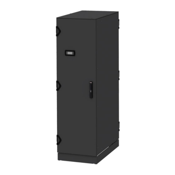
2 LHX+ overview The nVent SCHROFF LHX+ product family are closed electronics cabinets with integrated air-to-water heat exchangers installed at the bottom of the 19" plane. The following variants are available at the time of the compilation of this manual: Part-No. - Page 9 Cooling module 5 kW Cooling module 10 kW 1 Water outlet 4 Bleeding valve 2 Water inlet 5 Actuator water valve 3 Condensate drain (10 mm) 6 Fused mains input IEC60320-C14 The cooling modules contain no user serviceable parts inside; the fan trays are hot swappable.
-
Page 10: Functional Description
Functional description The cooling system consists of an air loop and a water loop. The fans of the cooling unit draw warm air from the rear section of the cabinet and into an air/water heat exchanger. The air is cooled down and then blown into the front area of the cabinet. -
Page 11: Cooling Capacity Control
Cooling capacity control Controller Box RJ45 connector Ethernet Air inlet for differential pressure sensor RJ45 connector RS485 (Modbus RTU) Controller box rear view Controller box front view Door contact rear door/rear panel Door contact front door The LHX+ controller is located together with the differential pressure sensor in a 2 U / 19” controller box (6) at the top of the cabinet. -
Page 12: Transport And Assembly
3 Transport and assembly Safety rules for transport and assembly ⚠ WARNING Risk of injury and/or material damage from falling or tipping loads! When transporting the cabinet with a pallet truck, forklift or crane, do not step under the suspended load. ... -
Page 13: Unpacking
Unpacking The LHX+ is delivered on a pallet. Remove any transport material and packaging. Dispose of the transport and packaging material in an environmentally compliant manner and in accordance with the applicable local rules and regulations. Leave the cabinet on the pallet to transport it to its destination. Check the LHX+ after unpacking for transport damage or other damage. -
Page 14: Placing The Cabinet
Placing the cabinet ⚠ WARNING Risk of injury and/or material damage from falling or tipping loads! When transporting the cabinet with a pallet truck, forklift or crane, do not step under the suspended load. Only use approved equipment and slings to lift the cabinet. ... -
Page 15: Lifting The Cabinet From The Pallet
3.3.1 Lifting the cabinet from the pallet The following steps describe how to lift the cabinet from the pallet with a forklift truck. 1) Transport the cabinet on the pallet to the installation site and remove the fastening screws with which the cabinet is fixed on the pallet. Note: For 800 mm deep cabinets, the fan trays must be removed first. -
Page 16: Commissioning
Commissioning The cabinet is completely wired and preconfigured. After connecting the power and water supply, it can be put into operation. ATTENTION Damage due to leaking water! Fittings may have loosened due to transport or during installation. Before commissioning, all fittings of the water circuit must be checked and tightened if necessary. -
Page 17: Connection To The Cooling Water Supply
3.4.1 Connection to the cooling water supply ATTENTION Outflow of cooling water can cause damage! Connection to the cooling water supply should be carried out by a refrigeration engineer or suitably trained plumber. It must be ensured that suitable structural measures (leak sensor, automatic shut- off valves) prevent damage to surrounding components in the event of a leak or defect. -
Page 18: Requirements For The Water Quality
3.4.2 Requirements for the water quality ATTENTION Risk of corrosion! If aluminum is used in the external water circuit, there is a risk of corrosion. To avoid electrochemical corrosion, the compatibility of the materials used in the cooling module with those of the external cooling circuit must be observed. ... -
Page 19: Water Connection
3.4.3 Water connection Cabinet bottom view The water return (3) and supply (4) connections are located under the bottom plate of the cabinet. During transport, the water connections are protected by an angled sheet metal (2). To remove the sheet metal and access the water connections you have to remove the lower side panels (1). -
Page 20: Bleeding The Cooling Module
Bleeding the cooling module ATTENTION Risk of damage! To avoid damage, the cooling module must be disconnected from the power supply during bleeding. Before commissioning, the device must be bleeded. Have the refrigeration engineer/plumber open the water flow to the cabinet. ... -
Page 21: Mains Connection
3.5.1 Mains connection ⚠ WARNING Power cable rating If the was not supplied with AC power cables, purchase AC power cables approved for use in your country. The AC power cables must be rated for the product and for the voltage and current marked on the product's electrical ratings label. -
Page 22: Mains Inputs
3.5.2 Mains inputs The cabinet has two IEC60320-C14 AC power inputs. One AC power input is located on the controller box at the top of the cabinet, the other at the bottom at the cooling module. To put the device into operation, both inputs must be powered. Power input cooling module Fuse Ground Stud (M6) -
Page 23: Connectors Controller Box
Connectors controller box IEC60320-C14 connector Connector for temperature sensors Ground Stud (M6) Connector for door contacts Connector for optional flow and Connector for remote display temperature sensor Connector for cooling module fan RJ45 connector Ethernet control Connector for valve actuator 10 RJ45 connector RS485 (Modbus RTU) 3.6.1 Plug in/Unplug connectors at the controller box The plugs are protected against disconnection by a locking mechanism. -
Page 24: Initial Operation
Initial operation The cabinet is equipped with door contact switches. When the doors are open, the fans are disabled and the control valve is closed. To ensure proper function and cooling performance, the front 19" plane must be sealed off from the rear part of the cabinet by suitable air baffle plates and seals. -
Page 25: Monitoring And Configuration
It is also possible to configure and monitor the operating parameters via Modbus TCP (IP) or Modbus RTU (RS485). For this purpose the LHX controller can be connected to the nVent Schroff Guardian Management Gateway which natively supports the control of the LHX+ cooling module. - Page 26 Screen Terminal: Emulates the remote display. In this screen, all sensor data and operating parameters can be displayed and parameterized. A description of the functions can be found in the chapter "Display". Screen Alarms Screen Log Date: 2021/04/07 Page : 26 of 47...
- Page 27 Date: 2021/04/07 Page : 27 of 47...
- Page 28 Screen Upgrade Date: 2021/04/07 Page : 28 of 47...
-
Page 29: Display
Display The display is mounted on the front door of the LHX+ 10130-326/327 cabinets and allows configuring the LHX+ controller or retrieve the operating parameters. Date: 2021/04/07 Page : 29 of 47... -
Page 30: Display Overview
4.2.1 Display Overview The temperature displayed depends on the operating mode of the temperature control. In the example above, it is the average of the cold air temperature sensors. Date: 2021/04/07 Page : 30 of 47... -
Page 31: Display Menu
4.2.2 Display menu Date: 2021/04/07 Page : 31 of 47... -
Page 32: Settings
4.2.3 Settings The cold air temperature is detected by 2 temperature sensors. The temperature sensors are mounted in front of the 19” plane at different heights to compensate the temperature stratification. As a control variable for the opening behavior of the control valve, the temperature of the lower ("cold bottom"), the upper ("cold top") or the average value of these temperature sensors can be used. - Page 33 Water valve control variables SET (S2) Control Valve The following parameters are available: Average Air Temp Temp Air Bottom Temp Air Top Manual If a temperature sensor makes the control, the temperature can be set in °C (°F), with manual control, the opening ratio of the water valve can be set in %.
-
Page 34: Maintenance
5 Maintenance If the operating conditions have been observed, the LHX+ is maintenance-free. The fan trays can be replaced. Fan tray replacement ATTENTION The cooling module must be switched off before removing the fan. If this is not done automatically, e.g. by the door contact switch, please unplug the power plug. -
Page 35: Optional Water Kit
6 Optional water kit In order to monitor additional operating parameters, a water kit (available as an accessory) can be mounted. The water kit is mounted in the water return and monitors water flow and return temperature. If the water kit is retrofitted, the controller must be configured accordingly. For further information please contact SCHROFF Service. -
Page 36: Installing The Water Kit
Installing the water kit ATTENTION Outflow of cooling water can cause damage! Works on the cooling water supply should be carried out by a refrigeration engineer or suitably trained plumber. Close the tap in the water supply Open the vent valve (1) ... -
Page 37: Dismantling, Storage And Disposal
7 Dismantling, storage and disposal Safety rules for dismantling, storage and disposal ⚠ WARNING Risk of injury and/or material damage from falling or tipping loads! When transporting the cabinet with a pallet truck, forklift or crane, do not step under the suspended load. ... -
Page 38: Dismantling
Dismantling ATTENTION Outflow of cooling water can cause damage! Works on the cooling water supply should be carried out by a refrigeration engineer or suitably trained plumber. Before any dismantling work can be started, the controller and cooling module must be disconnected from the mains. -
Page 39: Technical Data
8 Technical data Type LHX+ 5 kW LHX+ 5 kW LHX+ 10 kW Part No. 10130-325 10130-326 10130-327 Part No. Heat Exchanger 29714-017 29714-017 29714-016 Cooling capacity Usable cooling capacity 5 kW 5 kW 10 kW (cooling water inlet temperature 10 °C, air exit temperature 20 °C) Water circuit Cooling medium... -
Page 40: Scope Of Delivery
Scope of delivery Part No.: 10130-325 Pos. Designation VARISTAR FRAME SL 2000x600x800 mm (H/W/D), RAL7021 VARISTAR IP GASKET KIT BASE PLINTH H=100 mm, 3 COVERS + LEVELING FEETS + BRUSH AT THE REAR, RAL7021 BOTTOM PLATE 600x800 mm WITH IP CABLE ENTRY, ALUZINC COATED TOP COVER 600x800 mm RAL7021 PANEL / SLIDE MOUNT 19"... - Page 41 VARISTAR EMC FRAME SL 2000x600x1000 mm (H/W/D), RAL7021 VARISTAR EMC GASKET KIT BASE PLINTH H=100 mm, 3 COVERS + LEVELING FEETS + BRUSH AT THE REAR, RAL7021 EMC BOTTOM PLATE 600x1000 mm WITH EMC CABLE ENTRY, ALUZINC COATED EMC TOP COVER 600x1000 mm RAL7021 PANEL / SLIDE MOUNT 19"...
-
Page 42: Spare Parts
Spare parts Spare parts Part No. Item 23130-666 Display 23130-667 Door Switch Kit 23130-668 Controller Box 23130-669 Actuator and ball valve 29714-026 Fan Tray LHX 5 29714-025 Fan Tray LHX 10 Date: 2021/04/07 Page : 42 of 47... -
Page 43: Accessoires
Accessoires Accessoires Part No. Item 23130-660 LHX+ water hoses connection kit 1.5 m 23130-661 LHX+ water hoses connection kit 4 m 23130-663 Water flow and temperature sensor kit Date: 2021/04/07 Page : 43 of 47... - Page 44 23130-662 Water hoses duct for rear panel Date: 2021/04/07 Page : 44 of 47...
-
Page 45: Cooling Performance
Cooling performance Cooling performance LHX+ 5 kW Cooling performance LHX+ 10 kW Date: 2021/04/07 Page : 45 of 47... -
Page 46: Air Flow
Air flow Air flow LHX+ 5 kW Air flow LHX+ 10 kW Date: 2021/04/07 Page : 46 of 47... -
Page 47: Noise Level
Noise Level Noise level LHX+ 5 kW Noise level LHX+ 10 kW Date: 2021/04/07 Page : 47 of 47... - Page 48 last save 02/03/2021 DETAIL C DETAIL A BOTTOM VIEW (WITHOUT BRUSCH AND PIPE PROTECTION) 91,14 71,08 BSPP G3/4" (ISO 228-1) angle β according ISO8434-6 FRONT VIEW FRONT VIEW SIDE VIEW REAR VIEW WITHOUT DOOR ISOMETRIC VIEW (HORIZONTAL CUT) 600,00 822,50 TOP VIEW Utilisation initiale Echelle...
- Page 49 last save 02/03/2021 BOTTOM VIEW DETAIL B (WITHOUT BRUSCH AND DETAIL C PIPE PROTECTION) 91,14 71,08 BSPP G3/4" (ISO 228-1) angle β according ISO 8434-6 FRONT VIEW WITHOUT DOOR REAR VIEW 10130-326 REAR VIEW 10130-327 FRONT VIEW SIDE VIEW 999,60 (600,00) (1048.00) TOP VIEW...
- Page 50 Toute communication ou reproduction de ce document, toute exploitation ou communication de son The reproduction, distribution and utilization of this document as weil as the communication of its contenu sont interdites, sauf autorisation expresse. Tout manquement à cette règle est illicite et expose contents to others without express authorization is prohibited.
- Page 51 Toute communication ou reproduction de ce document, toute exploitation ou communication de son The reproduction, distribution and utilization of this document as weil as the communication of its contenu sont interdites, sauf autorisation expresse. Tout manquement à cette règle est illicite et expose contents to others without express authorization is prohibited.
Need help?
Do you have a question about the LHX+ and is the answer not in the manual?
Questions and answers