Table of Contents
Advertisement
Quick Links
Advertisement
Table of Contents

Related Manuals for Elcometer 121/2


Summary of Contents for Elcometer 121/2
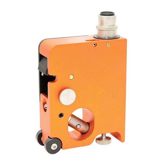
- Page 1 Elcometer 121/2 Universal Paint Inspection Gauge Operating Instructions...
- Page 2 (electronic, mechanical, magnetic, optical, manual or otherwise) without the prior written permission of Elcometer Ltd. A copy of this Instruction Manual is available for download on our Website via www.elcometer.com/downloads...
-
Page 3: Table Of Contents
CONTENTS Section Page About your gauge ..............2 Getting started. -
Page 4: About Your Gauge
Our products cover all aspects of coating inspection, from development through application to post application inspection. The Elcometer 121/2 Universal P.I.G. is a world beating product. With the purchase of this instrument you now have access to the worldwide service and support network of Elcometer. For more information visit our website at www.elcometer.com... - Page 5 1.1 STANDARDS The Elcometer 121/2 Paint Inspection Gauge can be used in accordance with the following National and International Standards: ASTM D 4138 ASTM D 3359-B BS EN 3900-CS-5B BS EN ISO 2815 DIN 53151 DIN 53153 ISO 2808-5B ISO 2409 1.2 WHAT THE BOX CONTAINS...
-
Page 6: Getting Started
2 GETTING STARTED 2.1 FITTING BATTERIES The Elcometer 121/2 Universal P.I.G. uses dry cell batteries only. To fit or replace the battery: Use a coin to loosen and open the slotted screw beside the eye-piece. Remove battery and replace with new battery 1.5 V (leakproof), positive end first. Reclose in reverse order. -
Page 7: Mounting And Changing Tools
3 MOUNTING AND CHANGING TOOLS All tools are mounted onto the rotary head: 1. Cutting Tool No. 1 2. Cutting Tool No. 2 3. Cutting Tool No. 3 4. Cross hatch cutter 5. Cross hatch cutter 6. Buchholz Indentation Tool 3.1 MOUNTING THE TOOLS : Positions 1, 2 and 3. - Page 8 3.2 CHANGING TOOLS When changing from one cutter to another, first press the ‘Stop’ knob against the casing. Then turn the rotary head to the desired position and lock it by releasing the ‘Stop’ knob. Note: Care must be taken that the ‘Stop’ knob distinctly and audibly snaps into place.
-
Page 9: Measuring Film Thickness
4 MEASURING FILM THICKNESS 1. Mark the surface to be tested with a stroke of the black Count number of graticule divisions marker pen provided with your gauge. There should always be a distinct contrast between the colour of the pen ink and the coating. - Page 10 7. Measure the width of the cut coating (or coatings) by counting the number of graticule divisions. To convert the width of the cut coating into coating thickness, multiply the number of graticule divisions by the resolution given below. Resolution of graticule Maximum thickness Cutting angle Cutter No.
- Page 11 IRREGULAR, SHELL-LIKE CUT Draw a straight line through the best estimate of the centre of the irregular cut edge using the graticule scale. This will give a mean value for thickness. POOR ADHESION (GIVES THE ILLUSION OF TOO LITTLE FILM THICKNESS) Cutter knife Despite the fact that the coating may have fractured at point ‘x’, coating...
-
Page 12: Measuring Cross-Cut Adhesion
5 MEASURING CROSS-CUT ADHESION The cross hatch cutter scores through the coating right down to the next coating layer or down to the substrate. Two cuts are made at right angles to each other resulting in a grid of small squares. Adhesion is then assessed visually by comparing the grid of squares against ISO, ASTM or Corporate Standards. - Page 13 Table 1: Cross-Cut Adhesion - Classification of Test Results Surface Description ASTM The edges of the cuts are completely smooth; none of the squares of the lattice is detached. Detachment of flakes of the coating at the intersections of the cuts. A cross cut area not significantly greater than 5% is affected.
-
Page 14: Measuring Indentation Hardness (Buchholz)
6 MEASURING INDENTATION HARDNESS (BUCHHOLZ) This test is carried out with the Indenting Tool (tool No. 6) in conjunction with the slip-on weight, and in accordance with DIN 53 153. The indenting tool incorporates a disc which has a sharp bevelled edge. Pressure between the disc and the coating results in an indentation being formed in the coating. - Page 15 Table 2: Buchholz indentation - Classification of test results Minimum coating thickness for which Indentation length Indentation depth Indentation a measurement is valid resistance (mm) (µm) (mils) (µm) (mils) 0.59 0.85 0.24 0.79 0.28 0.79 0.95 0.28 0.79 0.31 0.79 1.05 0.35 0.79...
-
Page 16: Spare Parts And Accessories
7 SPARE PARTS AND ACCESSORIES The following spare and optional items are available from Elcometer, or your local supplier. Cutter No. 1, 20 µm to 2000 µm (0.8 mils to 70 mils) T12112191 Cutter No. 2, 10 µm to 1000 µm (0.4 mils to 40 mils) T12112192 Cutter No. -
Page 17: Fault Checklist
Remove slotted screw and scratch upper surface of battery casing vigorously with coin until oxidated metal is bare again Break in circuit Return the gauge to your Elcometer supplier Battery cannot be removed Unsuitable, non leakproof Return the gauge to your Elcometer supplier... -
Page 18: Maintenance
Elcometer website, www.elcometer.com 10 RELATED EQUIPMENT In addition to the Elcometer 121/2 Universal P.I.G., Elcometer produces a wide range of other equipment for testing and measuring the characteristics of coatings. Users of the Elcometer 121/2 may also benefit from the following Elcometer products: •...
Need help?
Do you have a question about the 121/2 and is the answer not in the manual?
Questions and answers