Table of Contents
Advertisement
Quick Links
Advertisement
Table of Contents

Related Manuals for Bercomac BERCO 701029


Summary of Contents for Bercomac BERCO 701029
- Page 1 OWNER’S MANUAL Model number #701029 700981BER BERCO Manual rotation kit residential use *ASSEMBLY *REPAIR PARTS *OPERATION *MAINTENANCE CAUTION: READ & FOLLOW ALL SAFETY RULES & INSTRUCTIONS BEFORE OPERATING YOUR EQUIPMENT 01100640 R-06032021 110064_EN...
-
Page 2: Table Of Contents
Table of contents Table of contents Introduction ..................................1 Important safety information .............................. 2 Safety alert symbol/Signal words/Safety messages ......................2 Assembly and initial set-up ..............................3 General assembly instructions ............................3 Assemblage de l’accessoire ............................. 3 Installation of rotation rings: ............................3 Installation of the rotation worm .......................... -
Page 3: Introduction
Introduction Introduction To the purchaser This new accessory was carefully designed to give years of dependable service. This manual has been provided to assist in the safe operation and servicing of your attachment. All photographs, illustrations and information in the manual may not necessarily depict the actual models or attachments, but are intended for reference only and are based on the latest product information available at the time of publication. -
Page 4: Important Safety Information
Important safety information Important safety information Safety alert symbol/Signal words/Safety messages These are common practices that may or may not be applicable to the product described in this manual. SAFETY ALERT SYMBOL THIS SAFETY ALERT SYMBOL IDENTIFIES AN IMPORTANT SAFETY MESSAGE IN THIS MANUAL THAT HELPS YOU AND OTHERS AVOID PERSONAL INJURY OR EVEN DEATH. -
Page 5: Assembly And Initial Set-Up
Assembly & initial set-up Assembly and initial set-up General assembly instructions • Unless otherwise specified, torque all bolts to “torque specification table” (see table of content for page number) • Refer to parts breakdown section for part identification. Assemblage de l’accessoire Installation of rotation rings: A. -
Page 6: Installation Of The Handle Support
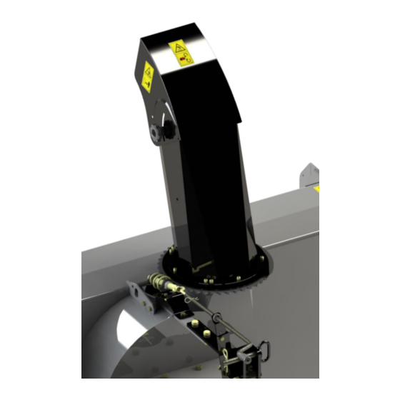
Assembly & initial set-up is installed and the snowblower is installed on the tractor) and secure in place with two hex bolts 5/16" n.c. x 3/4" (item 3) and nylon insert lock nuts (item 4). Position the worm assembly (item 1) on the frame of the snowblower in the location shown. -
Page 7: Operating Instructions
Operating instructions Operating instructions Controls Chute rotation Turn the handle clockwise to rotate the chute to the right and counter clockwise to rotate to the left. -
Page 8: Part List And Parts Breakdown
Parts breakdown Part list and parts breakdown... - Page 9 Parts breakdown...
-
Page 10: Torque Specification Table
Torque specification table Torque specification table TO BE USED WHEN A TIGHTENING TORQUE IS NOT SPECIFIED IN THE TEXT • The following table shows the minimum torque requirement • Maximum is 15% more than the minimum (example: min100 Nm -> max is 115Nm) •... -
Page 11: Warranty
NOTE: All warranty work must be performed by an authorized dealer using original (manufacturer) replacement parts. NOTE: Bercomac reserves the right to change or improve the design of any part or accessory without assuming any obligation to modify any product previously manufactured. - Page 12 WHEN PERFORMANCE & DEPENDABILITY ARE NON NEGOTIABLE ! Bercomac Limitée 92, Fortin North, Adstock, Quebec, Canada, G0N 1S0 WWW.BERCOMAC.COM PRINTED IN CANADA (ORIGINAL NOTICE)
Need help?
Do you have a question about the BERCO 701029 and is the answer not in the manual?
Questions and answers