Table of Contents
Advertisement
Quick Links
READ & FOLLOW ALL SAFETY RULES & INSTRUCTIONS
104313
BERCO
Rotary Broom
LAWN, YARD, & GARDEN TRACTORS
BELT OR SHAFT DRIVE P.T.O.
* ASSEMBLY
* OPERATION
CAUTION:
BEFORE OPERATING YOUR EQUIPMENT
OWNER'S MANUAL
Model number
700286-1 (
700316-1 (
Polypropylene brush)
for
* REPAIR PARTS
* MAINTENANCE
1
Nylon brush)
G-03
Advertisement
Table of Contents

Related Manuals for Bercomac BERCO 700286-1


Summary of Contents for Bercomac BERCO 700286-1
- Page 1 OWNER’S MANUAL Model number 700286-1 ( Nylon brush) 700316-1 ( Polypropylene brush) BERCO Rotary Broom LAWN, YARD, & GARDEN TRACTORS BELT OR SHAFT DRIVE P.T.O. * ASSEMBLY * REPAIR PARTS * OPERATION * MAINTENANCE CAUTION: READ & FOLLOW ALL SAFETY RULES & INSTRUCTIONS BEFORE OPERATING YOUR EQUIPMENT 104313 G-03...
- Page 2 NOTE: All warranty work must be performed by an authorized dealer using original (manufacturer) replacement parts. Note: Bercomac reserves the right to change or improve the design of any part or accessory without assuming any obligation to modify any product previously manufactured. Instructions for Obtaining Warranty Services: Contact dealer where equipment was purchased or any other BERCOMAC Service Dealer to arrange service at their dealership.
-
Page 3: Table Of Contents
TABLE OF CONTENTS PAGE INTRODUCTION ..............................SAFETY PRECAUTIONS ............................. SAFETY DECALS ..............................ASSEMBLY Step 1: Rotary Broom Preparation ......................Step 2: Rotary Broom Installation ......................Handle Installation ........................Verify Tire Pressure ........................OPERATION Rotary Broom Angle Adjustment ......................Pressure on the Brush Adjustment ......................General Sweeping ........................... -
Page 4: Introduction
INTRODUCTION TO THE PURCHASER This new attachment was carefully designed to give years of dependable service. This manual has been provided to assist in the safe operation and servicing of your attachment. NOTE: All photographs and illustrations in the manual may not necessarily depict the actual models or attachment, but are intended for reference only and are based on the latest product information available at the time of publication. -
Page 5: Safety Precautions
SAFETY PRECAUTIONS Careful operation is your best insurance against an accident. Read this section carefully before operating the tractor and the rotary broom. All operators, no matter how experienced they may be, should read this and other manuals related to the tractor and rotary broom before operating. It is the owner's legal obligation to instruct all operators in how to safely operate the rotary broom. - Page 6 SAFETY PRECAUTIONS MAINTENANCE AND STORAGE 5. Take all possible precautions when leaving the machine unattended. Disengage the power take- 1. Check the mounting bolts at frequent intervals to off, lower the attachment, set the parking brake, make sure that they are properly tightened stop the engine and remove the key.
-
Page 7: Safety Decals
SAFETY DECALS REPLACE IF DECALS ARE DAMAGED SEE PARTS BREAKDOWN FOR DECAL LOCATION Decal #102386 Decal #102384... -
Page 8: Assembly
ASSEMBLY STEP 1 ROTARY BROOM PREPARATION IMPORTANT: TORQUE ALL BOLTS ACCORDING TO TORQUE SPECIFICATION TABLE (SEE TABLE OF CONTENTS) WHEN STATED: TIGHTEN FIRMLY. REFER TO PARTS BREAKDOWN SECTION FOR PARTS IDENTIFICATION See adaptor mounting Instruction Booklet for adaptor preparation and installation of adaptor. -
Page 9: Step 2: Rotary Broom Installation
ASSEMBLY STEP 2 ROTARY BROOM INSTALLATION WARNING TO PREVENT INJURIES: Stop the motor. Apply parking brake. Remove the ignition key. Disconnect the wire from the spark plug(s) and keep away from spark plug(s) to prevent accidental starting. Attach the rotary broom to the subframe as shown. Make sure the rotary broom is pushed in until locked into place by the springs (item 1). -
Page 10: Operation
OPERATION WARNING WARNING PREVENT INJURIES MORE BEFORE MAKING ANY ADJUSTMENTS: TRACTION WHEN USING AN ATTACHMENT: Stop the motor. Apply parking brake. -Rear counterweights of 100 lbs. minimum are Remove the ignition key. required counter-balance attachment’s Disconnect the wire from the spark plug(s) and weight. -
Page 11: Maintenance & Dismounting
MAINTENANCE & DISMOUNTING MAINTENANCE DISMOUNTING Check oil level in gear box every fifty hours and fill Select a level surface, set parking brake, stop to plug level with SAE-90-EP oil when necessary. the engine, and remove the ignition key to prevent accidental starting. -
Page 12: Troubleshooting
TROUBLESHOOTING PROBLEM POSSIBLE CAUSES CORRECTIVE ACTION Brush wears out prematurely. The pressure on the brush is not Reduce the pressure on the brush well adjusted. when on the ground. Maintain the gauge even with the The brush turns jerkily. top of the gear box frame or lower when sweeping hard surfaces. -
Page 13: Torque Specification Table
TORQUE SPECIFICATION TABLE GENERAL TORQUE SPECIFICATION TABLE USE THE FOLLOWING TORQUES WHEN SPECIAL TORQUES ARE NOT GIVEN NOTE: These values apply to fasteners as received from supplier, dry or when lubricated with normal oil. They do not apply if special graphited or moly disulphide greases or other extreme pressure lubricants are used. This applies to both UNF and UNC threads. -
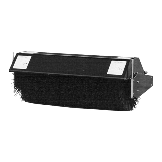
Page 14: Rotary Broom
PARTS BREAKDOWN / NOMENCLATURE DES PIÈCES ROTARY BROOM / BALAI ROTATIF... - Page 15 PARTS LIST / LISTE DES PIÈCES Ref. English description Description française Qty. Part # Réf. Qté. Pièce # 1 Handgrip Poignée 102062 2 Stand holder Support de pied 102392 3 Hex. bolt 1/4" n.c. x 1/2" Boulon hex. 1/4" n.c. x 1/2" 4 Parking stand Pied de stationnement 102394...
- Page 16 PARTS LIST / LISTE DES PIÈCES Ref. English description Description française Qty. Part # Réf. Qté. Pièce # 31 Carriage bolt 5/16" n.c. x 3/4" Boulon à carrosserie 5/16" n.c. x 3/4" 32 Collar Collet 102402 33 Flange nut 5/16" n.c. Écrou à...
- Page 17 PARTS LIST / LISTE DES PIÈCES Ref. Qty. Part # English description Description française Réf. Qté. Pièce # 61 Flange nut 1/4" n.c. Écrou à bride 1/4" n.c. 62 Hex. bolt 5/8" n.c. x 1 1/2" Boulon hex. 5/8" n.c. x 1 1/2" 63 Roller chain #40 x 86 links/conn.link Chaîne # 40 x 86 mailles/maille acc.
-
Page 18: Attachments
ATTACHMENTS SNOWBLOWER ROTARY TILLER #700312 #700210 40" #700211 44" Mounts to the rear of lawn, yard & UTILITY BLADE #700266 #700255 40" garden tractors 14 to 25 HP. Comes #700400 48" complete with drive & manual lift Mounts on the same subframe as the Fits on same subframe as rotary mechanisms &... - Page 19 NOTES...
Need help?
Do you have a question about the BERCO 700286-1 and is the answer not in the manual?
Questions and answers