
Related Manuals for Adeunis RF ARF54


Summary of Contents for Adeunis RF ARF54
- Page 1 RF54 UART TTL modules User Guide Downloaded from Elcodis.com electronic components distributor...
- Page 2 No part of this document may be reproduced or transmitted (in electronic or paper version, photocopy) without Adeunis RF consent. This document is subject to change without notice. All trademarks mentioned in this guide are the property of their respective owner.
-
Page 3: Table Of Contents
RF54 User Guide Table of Contents Table of Contents .....................1 About this Document..................2 Declaration of Conformity ................3 Overview ......................4 Interface ......................4 Mechanical specification..................4 Signal description ....................6 General purpose I/O extended functionality ............7 Radio communication..................10 Radio communication ..................10 Radio channels....................10 Channel adjustment ...................11 Radio rate selection....................11... -
Page 4: About This Document
RF54 User Guide About this Document RF54 This guide describes the A devices, their options and accessories. Ref. 08-07-V6-lmn p. 2 Downloaded from Elcodis.com electronic components distributor... -
Page 5: Declaration Of Conformity
CE label marking. - As the integration of a radio module requires wireless technological knowledge, ADEUNIS RF proposes its technical proficiency to its customers for a pre- compliance qualification of end products. In case of no-conformity, ADEUNIS RF will not be held back responsible if this stage has not been realised. -
Page 6: Overview
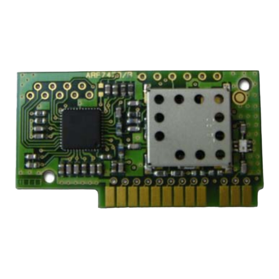
RF54 User Guide Overview The ARF54 radio transceiver converts data from a serial link into a radio frame to be sent to a similar piece of equipment. The communication is half-duplex. The operating parameters of these radio transceivers (serial link, radio management…) can be fully updated through AT commands via the serial... - Page 7 RF54 User Guide The PCB width is 12/10 mm Figure 1: Plugged module mechanical feature This module has been designed to be plugged (as describe above). If this assembly doesn’t suit your requirement, please have a look to Annex 1 (mainly for horizontal mounting).
-
Page 8: Signal Description
RF54 User Guide Signal description Inter- Description Alternate face Name function Digital interface Ground Operating voltage Serial data transmission Serial data reception Request To Send RTS = GND, the transceiver is able to /RTS receive serial data RTS = VDD, serial data received by the transceiver are lost /RESET Transceiver Hardware RESET, active LOW. -
Page 9: General Purpose I/O Extended Functionality
RF54 User Guide Description Unit Vil1 Input low voltage except -0.5 0.3VDD /RESET Vih1 Input High voltage except 0.6VDD VDD+0.5 /RESET Vil2 /RESET Input low voltage -0.5 0.2VDD Vih2 /RESET Input High voltage 0.9VDD VDD+0.5 /RESET pulse width µs General purpose I/O extended functionality RS485 interface The S215 register allows enabling the management of the control lines (/RE and DE lines) of most RS485 buffer. - Page 10 RF54 User Guide AUTION • the /ENABLE485 is read ONLY at power-up. Changing the /ENABLE485 (GPIO7) when the transceiver is already running will not be taken in account. • when activating the RS485 interface the GPIO5 will be set as an output.
- Page 11 RF54 User Guide By default, the DE and RE lines are asserted LOW, allowing the reception of characters from the RS485 differential bus. The DE and RE lines are asserted HIGH only when one or several characters have to be transmitted over the RS485 differential bus: when a radio frame is demodulated, the lines are asserted HIGH and then the data extracted from the radio frame are sent to the module TXD line and therefore to the RS485 differential bus.
-
Page 12: Radio Communication
RF54 User Guide Radio communication Radio communication 869 MHz version This modem has several channels over the 863-870 MHz Band that can be selected using AT commands, distributed in Wide Band and Narrow Band. Wide Band channel : • 1 Wide Band channels •... -
Page 13: Channel Adjustment
RF54 User Guide The 3 Narrow Band channels are selected according to the following table : Channel Frequency S200 (MHz) 869,450 869,525 869,600 Figure 5: Narrow Band channels Channel adjustment The S200 register allows choosing the desired channel and the associated see chapter “AT commands”... -
Page 14: Rssi Reading
RF54 User Guide -2000 -1750 -1500 -1250 -1000 -750 -500 -250 1000 1250 1500 1750 2000 frequency step / Fchannel (kHz) Particular attention is required for product installation. In the case where several links must works in the same area (independently of the channel positions), the minimum distance between 2 products belonging to different radio links is 3 meters. -
Page 15: Transceiver Operating Mode
RF54 User Guide Transceiver operating mode Two operating modes are available : Command mode (usage of AT commands) Transceiver or normal mode (serial data are transmitted on radio link) At power up the transceiver is in transceiver mode: it is able to send / receive data to / from the radio link according to its current parameter configuration. -
Page 16: Transceiver Mode
RF54 User Guide Exiting command mode (return back in transceiver mode): send the serial command ATO <cr> Transceiver mode In transceiver mode, two protocols are available: Transparent mode, without flow control. Addressed mode, with flow control (see register S216) The communication is always half-duplex. The radio transmission is processed prior to the radio reception (when the transceiver is sending a radio frame, it is not able to decode any incoming radio frame). -
Page 17: Transparent Mode
RF54 User Guide Transparent mode In transparent mode, the modem acts as a wire serial link. It means that alternately, the modem sends on the radio the data received from the serial link and sends on the serial link the data received from the radio. The radio frame format is : •... -
Page 18: At Commands
RF54 User Guide link, the radio frame will be discarded and the RS232 incoming data will be processed). Processing incoming RS232 data : the incoming RS232 data are internally buffered. The buffered data are sent in a radio frame (the RF modulation is started) when almost one of the following conditions occurs: if a break (silence greater than S217 timeout) is detected on the incoming serial flow (no more data to be sent). -
Page 19: Set Of Commands
Sxxx=y<cr><lf> for each register. AT/V Software version display. The response has the following format: Adeunis RF Versatile Modem II 868 MHz 500mW Vxx.yy<cr><lf> Restore the register default values ATPWD=m m = pin code (register S205) : unlock all AT commands. -
Page 20: Register Description
RF54 User Guide Register description The register value could be updated using the ATSn=m<cr> command and displayed using ATSn?<cr> command. At power-up, the previous transceiver configuration is restored from E2PROM (non volatile) to RAM. The registers are located in RAM registers, any modification is performed on RAM registers: To save current register configurations, it is necessary to use the AT&W<cr>... - Page 21 RF54 User Guide Type Register Function Description Default Note value S218 Radio frame Size of the radio frame (from 1 up to 240). length When this size is reached: the transceiver sends a radio frame The RTS signal is activated (pull to VDD) only if the module is operating in the addressed mode.
- Page 22 RF54 User Guide Type Register Function Description Default Note value S213 Stop bits ‘1 ‘ : 1 stop bit ‘2’ : 2 stop bit S214 Command Time out duration for detecting the +++ timeout pattern, unit ms. From 3 up to 240. S215 Interface type ‘0’...
- Page 23 RF54 User Guide characters in the requested speed (13 ms for 2400 bauds, 7 ms for 4800, 3 ms otherwise). streaming mode without flow control. Be careful using a serial rate greater to the radio rate must produce character losts if the flow control is not used. If the radio rate is equal to the serial rate, the radio frame is longer than the serial frame, due to radio protocol overhead;...
-
Page 24: Power Management (Standby Mode And Low Power Mode)
RF54 User Guide when changing the serial link configuration (rate, parity, stop bit…), the answer is done using the old serial link format, the next command must be sent using the new serial format. the S232 management is described in the following paragraph. Power management (standby mode and low power mode) Two modes are available for power management :... - Page 25 RF54 User Guide Enable Low Power down mode : The low power down mode is managed only after its activation. Applying a High level on the PWD signal when the mode has not been activated has no effect the module is still running in its current mode. In command mode, send the AT command ATS232=2<cr>.
-
Page 26: Specifications
RF54 User Guide Specifications 868 / 870 MHz European version Embedded protocol ADEUNIS RF enhanced & versatile RF comms manager Embedded profiles High Data rate Monochannel modem Middle Data Rate Monochannel modem Link set-up and status Through Hayes commands Radio rough data rate 10 000 &... -
Page 27: Glossary
RF54 User Guide Glossary To Be Defined Not Connected Not Used FHSS Frequency Hopping Spread Spectrum FIFO First In First Out Wide Band Narrow Band ANNEX 1 : Alternative mounting If the module cannot be plugged directly on the motherboard, it is possible to mount a connector. -
Page 28: Annex 2 : Firmware Updates
RF54 User Guide ANNEX 2 : Firmware updates Firmware Updates V00.18 Pin code added Document Updates NB configuration when leaving factory, electrical specification VIx/VOx Pin code added (LMN) Ref. 08-07-V6-lmn p. 26 Downloaded from Elcodis.com electronic components distributor...
Need help?
Do you have a question about the ARF54 and is the answer not in the manual?
Questions and answers