
Related Manuals for Adeunis RF ARF54


Summary of Contents for Adeunis RF ARF54
- Page 1 RF54 UART TTL modules User Guide Downloaded from Elcodis.com electronic components distributor...
- Page 2 No part of this document may be reproduced or transmitted (in electronic or paper version, photocopy) without Adeunis RF consent. This document is subject to change without notice. All trademarks mentioned in this guide are the property of their respective owner.
-
Page 3: Table Of Contents
RF54 User Guide Table of Contents Table of Contents ................1 About this Document ................ 2 Overview ................... 3 Interface ................... 3 Mechanical specification................3 Signal description .................5 General purpose I/O extended functionality ...........6 Radio communication ............... 9 Radio channels & Sub Bands ..............9 Channel selection ................ -
Page 4: About This Document
RF54 User Guide About this Document RF54 This guide describes the A devices, their options and accessories. Ref. 08-07-V6-lmn p. 2 Downloaded from Elcodis.com electronic components distributor... -
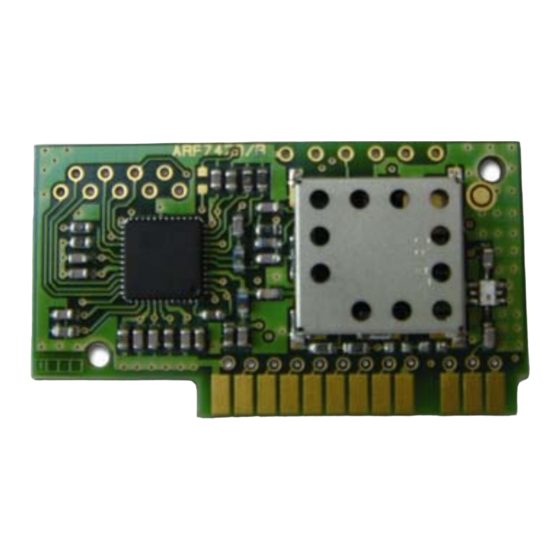
Page 5: Overview
RF54 User Guide Overview RF54 The A radio transceiver converts data from a serial link into a radio frame to be sent to a similar piece of equipment. The communication is half-duplex. The operating parameters of these radio transceivers (serial link, radio management…) can be fully updated through AT commands via the serial link. - Page 6 RF54 User Guide Figure 1: Plugged module mechanical feature This module has been designed to be plugged (as describe above). If this assembly doesn’t suit your requirement, please have a look to Annex 1 (mainly for horizontal mounting). Ref. 08-07-V6-lmn p.
-
Page 7: Signal Description
RF54 User Guide Signal description Inter Description Alternate function -face Name Digital interface Ground Operating voltage Serial data transmission Serial data reception Request To Send RTS = GND, the transceiver is able /RTS receive serial data RTS = VDD, serial data received by the transceiver are lost Transceiver Hardware RESET, active /RESET... -
Page 8: General Purpose I/O Extended Functionality
RF54 User Guide Description Unit Vil1 Input low voltage except -0.5 0.3VDD /RESET Vih1 Input High voltage except 0.6VDD VDD+0.5 /RESET Vil2 /RESET Input low voltage -0.5 0.2VDD Vih2 /RESET Input High voltage 0.9VDD VDD+0.5 /RESET pulse width µs General purpose I/O extended functionality RS485 interface The S215 register allows enabling the management of the control lines (/RE and DE lines) of most RS485 buffer. - Page 9 RF54 User Guide AUTION • the /ENABLE485 is read ONLY at power-up. Changing the /ENABLE485 (GPIO7) when the transceiver is already running will not be taken in account. • when activating the RS485 interface the GPIO5 will be set as an output.
- Page 10 RF54 User Guide asserted HIGH and then the data extracted from the radio frame are sent to the module TXD line and therefore to the RS485 differential bus. When the last character has been transmitted over the RS485 differential bus, the lines are asserted LOW.
-
Page 11: Radio Communication
RF54 User Guide Radio communication This modem has 50 channels over the 902-928 MHz Band used through FHSS transmission. Hopping is possible over the whole range but also selectable over up or down sub-bands. These modes can be selected using AT commands. -
Page 12: Channel Selection
RF54 User Guide Channel Frequency Channel Frequency S200 (MHz) S200 (MHz) Low Sub Band High Sub Band 902.75 915.25 903.25 915.75 903.75 916.25 904.25 916.75 904.75 917.25 905.25 917.75 905.75 918.25 906.25 918.75 906.75 919.25 907.25 919.75 907.75 920.25 908.25 920.75 908.75 921.25... -
Page 13: Air Radio Rate Selection
RF54 User Guide Air radio rate selection TTENTION Radio rate default setup is 57600 bit/s. S202 = 0: 10 kbps Narrowband S202 = 1: 57.6 kbps Wideband Channel rejection The graph below shows the typical channels rejection in WideBand (WB) and NarrowBand (NB) modes. -
Page 14: Rssi Reading
RF54 User Guide RSSI reading The RSSI (Received Strength Signal Indicator) gives an indication for the received power level on the first channel of the hopping table. It could be accessed with ATS230?<cr> command. Power level • The RSSI level is only an indication. Use this level with care due to the dispersion between components. -
Page 15: Command Mode
RF54 User Guide Command mode The command mode is used to read and update the modem configuration registers using AT command. The AT command can be locked using ATPWD command. In command mode, the radio is inhibited (reception and transmission), excepted when using test command. -
Page 16: Transceiver Mode
RF54 User Guide Transceiver mode The transceiver mode used a secured addressed protocol. The communication is always half-duplex. The radio transmission is processed prior to the radio reception. When the transceiver is sending a radio packet, it is not able to decode any incoming radio packet. If no data are sent on the serial link, the modem is waiting for radio reception. -
Page 17: Power Management : Low Power Mode
RF54 User Guide Power management : low power mode The low power mode is managed with the S232 register and the STANDBY pin (5). Before the activation of the power down mode (ATS232=1<cr>) be sure that the STANDBY pin is pulled to GND in order to keep the module in active mode. -
Page 18: Set Of Commands
Sxxx=y<cr><lf> for each register. AT/V Software version display. The response has the following format: Adeunis RF Versatile Modem II 915 MHz 500mW Vxx.yy<cr><lf> Restore the register default values ATPWD=m m = pin code (register S205) : unlock all AT commands. -
Page 19: Register Description
RF54 User Guide Register description The register value could be updated using the ATSn=m<cr> command and displayed using ATSn?<cr> command. At power-up, the previous transceiver configuration is restored from E2PROM (non volatile) to RAM. The registers are located in RAM registers, any modification is performed on RAM registers: To save current register configurations, it is necessary to use the AT&W<cr>... - Page 20 RF54 User Guide Type Register Function Description Default Note value S231 RF OUT level Adjusts the RF out level 0 => 20 dBm (100 mW) 1 => 23 dBm (200 mW) 2 => 24,5 dBm (<450 mA for USB power supply) 3 =>...
- Page 21 RF54 User Guide Type Register Function Description Default Note value S219 RS485 delay Delay between DE activation and the first RS485 transmitted byte From 0 up to 160 Protocol S220 Protocol ‘2’= hopping all the band ‘3’= hopping low band ‘4’= hopping high band S221 Packet retries...
- Page 22 RF54 User Guide If the radio rate is equal to the serial baudrate, the radio packet is longer than the serial frame, due to radio protocol overhead. If the current radio rate is 10 kbit/s (Narrow band), a serial baudrate of 4800 bauds can be used without flow control, while using a serial baudrate greater or equal to 9600 bauds will produce data overrun.
-
Page 23: Specification
RF54 User Guide Specification 915 MHz North American European version Embedded protocol ADEUNIS RF enhanced & versatile RF comms manager Embedded profiles Full band FHSS modem Sub-Band FHSS modem Improved Full band FHSS modem Improved Sub-Band FHSS modem Link set-up and status... -
Page 24: Glossary
RF54 User Guide Glossary To Be Defined Not Connected Not Used FHSS Frequency Hopping Spread Spectrum FIFO First In First Out Wide Band Narrow Band ANNEX 1 : Alternative mounting If the module cannot be plugged directly on the motherboard, it is possible to mount a connector. -
Page 25: Annex 2 : Firmware Updates
RF54 User Guide ANNEX 2 : Firmware updates Firmware Updates V2.02 Pin code added Document Updates V6.0 Pin code added (LMN) V4.0 NB configuration when leaving factory, electrical specification VIx/VOx V2.0 Commands update V1.0 Original version Ref. 08-07-V6-lmn p. 23 Downloaded from Elcodis.com electronic components distributor...
Need help?
Do you have a question about the ARF54 and is the answer not in the manual?
Questions and answers