Table of Contents
Advertisement
Quick Links
Advertisement
Table of Contents

Related Manuals for Adeunis RF ARF44


Summary of Contents for Adeunis RF ARF44
- Page 1 RF44 UART TTL modules User Guide Ref. 08-07-V5-lmn p. 1...
- Page 2 No part of this document may be reproduced or transmitted (in electronic or paper version, photocopy) without Adeunis RF consent. This document is subject to change without notice. All trademarks mentioned in this guide are the property of their respective owner.
-
Page 3: Table Of Contents
RF44 User Guide Table of Contents About this Document ................ 2 Declaration of Conformity ..............3 Overview ................... 4 Interface ................... 4 Mechanical specification................4 Signal description .................5 Directions are noted from module point of view....... 5 Radio Communication ............... 5 Available Channels ................5 Channel selection .................6 Antenna requirements ................6... -
Page 4: About This Document
RF44 User Guide About this Document RF44 This guide describes the A devices, their options and accessories Ref. 08-07-V5-lmn p. 2... -
Page 5: Declaration Of Conformity
CE label marking. - As the integration of a radio module requires wireless technological knowledge, ADEUNIS RF proposes its technical proficiency to its customers for a pre- compliance qualification of end products. In case of no-conformity, ADEUNIS RF will not be held back responsible if this stage has not been realised. -
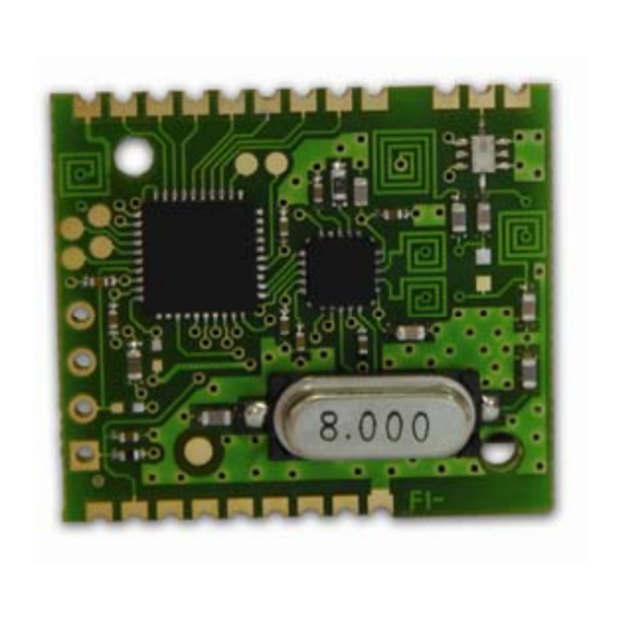
Page 6: Overview
RF44 User Guide Overview RF44 The A 4 radio transceiver converts data from a serial link into a radio frame to be sent to a similar piece of equipment. The communication is half- duplex. The operating parameters of these radio transceivers can be fully updated through AT commands via the serial link. -
Page 7: Signal Description
RF44 User Guide Signal description I/O direction Description Pin name number Power and reset Digital GND (connected with 1, 17, 18 radio GND) Power supply /Reset Reset RF interface Radio (connected with GND RF digital GND) RF in/out RF Antenna IN/OUT Masse radio (connected with GND RF digital GND) -
Page 8: Channel Selection
RF44 User Guide Channel Frequency S200 (MHz) 863,25 863,75 864,25 864,75 865,25 865,75 866,25 866,75 867,25 867,75 868,25 868,75 869,525 869,75 Channel selection The S200 register allows choosing the desired channel. Antenna requirements This module is not available with printed antenna. An external one has to be added to achieve correct communication between the products. -
Page 9: Transceiver Operating Mode
RF44 User Guide RSSI Reading The RSSI (Received Strength Signal Indicator) gives an indication for the received power level. It could be accessed with AT commands. -120 -100 -100 -120 Input Power (dBm) The RSSI level is only an indication. Use this level with care due to the dispersion between components. -
Page 10: Serial Data Rate
RF44 User Guide Transceiver or normal mode (serial data are transmitted on radio link) At power up the transceiver is in transceiver mode: it is able to send / receive data to / from the radio link according to its current parameter configuration. Serial data rate This module is only available with one data rate: 19200bps, 8 data bits, 1 stop bit, no parity, no flow control. -
Page 11: Transceiver Mode
RF44 User Guide Tips 2 : Idle line for S214 +++ (consecutive) Idle line for S214 duration duration line TRANSCEIVER MODE COMMAND MODE (return back in transceiver mode): send the serial Exiting command mode command ATO <cr> Transceiver mode In transceiver mode, the module works with a transparent protocol: When transmitting, data received from the serial link are transmitted on the radio link. -
Page 12: Powerdown Mode
RF44 User Guide Powerdown Mode In powerdown mode, the power consumption is reduced to reach less than 3µA. In this state, the module is not able to receive or transmit any data and is not able to enter command mode. The powerdown mode is controlled by pin 4 of the module. -
Page 13: Set Of Commands
Sxxx=y<cr><lf> for each register. AT/V Software version display. The response has the following format: Adeunis RF : ARF34 Vxx.yy<cr><lf> Restore the register default values ATPWD=m m = pin code (register S205) : unlock all AT commands. m = 0000 : set registers to default value and unlock all AT commands. -
Page 14: Register Description
RF44 User Guide ATT3 2.45 kHz modulation using current channel. The output of this mode is achieved by reception of any character on the serial link. ATT8 Reception test mode. TP1 is set when more than 80% of bits are demodulated properly. Register description The register value could be updated using the ATSn=m<cr>... -
Page 15: Transceiver State Machine
RF44 User Guide Transceiver state machine When operating in transceiver mode the 'RF transmission' state machine is: Idle state of the transceiver: by default the transceiver is waiting for incoming data on the serial link and for incoming radio frame on the radio link. -
Page 16: Specifications
RF44 User Guide Specifications Embedded protocol ADEUNIS RF enhanced & versatile RF comms manager Embedded profiles Multi-mode transceiver Custom profiles Designed on custom specifications Link set-up and status Through Hayes commands Radio rough data rate 19500 bps UART fixed format 19200 bps –... -
Page 17: Annex 1 : Firmware And Document
RF44 User Guide ANNEX 1 : Firmware and document updates Firmware Updates V1.00 Initial version V1.01 RSSI and pin code added Document Updates 07-06-V1-smn Initial version 08-01-V2-smn Update the mechanical schematic 08-05-V4-lmn RSSI added 08-07-V5-lmn Pin code added Ref. 08-07-V5-lmn p.
Need help?
Do you have a question about the ARF44 and is the answer not in the manual?
Questions and answers