Advertisement
Quick Links
Advertisement

Subscribe to Our Youtube Channel
Related Manuals for Yokomo SO 1.0


Summary of Contents for Yokomo SO 1.0
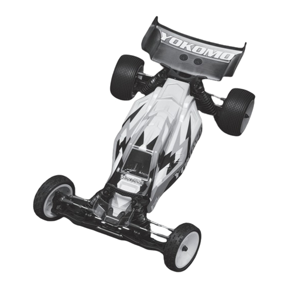
- Page 1 1/10 SCALE 2WD OFF-ROAD RACING CAR KIT...
- Page 2 走行してして下さい。 ① スピー ドコン トローラのスイッチをOFFにします。 ② バッテリーの接続を外します。 ③ 送信機のスイッチをOFFにし、 アンテナを縮めます。 Thank you for purchasing this Yokomo product. This high performance competition kit has been proudly manufactured by Yokomo - World Champion R/C car manufacturer. Proper assembly of this product will provide fun, safe enjoyment. PRECAUTIONS FOR SAFE ENJOYMENT OF YOUR R/C CAR For children under the age of 13, parental guidance is recommended when running. ■ ASSEMBLY PRECAUTIONS ■ ■ PRECAUTIONS BEFORE RUNNING ■ ■ BATTERY USAGE ■ ● Do not assemble around small children. The ● Yokomo R/C cars are built for competition use, and (Carefully read the instruction included with the batteries) parts can be dangerous if accidentally some models may exceed speeds of 40km per hour. ● When charging batteries, make sure that the swallowed. Practice common sense and run the car in open safe surrounding area is void of anything highly flammable. places, or R/C car tracks. ● Check the contents carefully before Also avoid charging in high-temperature locations. assembly. Please contact Customer Support ● Do not run the car on public roads with high amounts ...
- Page 3 Y T − C S 1A ハサミ 1 6 0mm ¥ 1485 YOKOMOレーシングツール 2.0㎜ ヘックス ドライバー ¥627 Y T − C S 2A 曲線バサミ ¥ 1485 YT-20RTRA レッ ド / YT-20RTBA ブラック ナッ ト ドライバー (7.0㎜、 5.5㎜) ボディーリーマー NUT DRIVER BODY REAMER YOKOMOレーシングツール 5.5㎜ナッ ト ドライバー ¥748 YOKOMOレーシングツール ボディ リーマー ¥1980 YT-55RTRA レッ ド / YT-55RTBA ブラック YT-BRRA レッ ド / YT-BRBA ブラック YOKOMOレーシングツール 7.0㎜ナッ ト ドライバー ¥748 YT-70RTRA レッ ド / YT-70RTBA ブラック 瞬間接着剤 QUICK DRYING GLUE ラジオペンチ...
- Page 4 メインシャシーの組立て Main Chassis Assembly このページで使用するパーツ Parts used on this page Z2-002S31A サイドプレート Side plate Z2-002CA メインシャシー ×1 Main Chassis ビス袋から必要に応じてお選びください。 Please choose from the screw bags as needed. ZC-F38A M3x8 サラキャップ ×6 FHS Screw ZC-F310A ZC-F38A Z2-002CA M3x8 サラビス M3x10 サラキャップ ×6 メインシャシー FHS Screw FHS Screw Main chassis 袋 #0 の内容 Bag #0 Contents ZC-F310A M3x10 サラビス Z2-002S31A FHS Screw サイドプレート L&R 各 1 Side plate L & R 1Ea ベルクランクの組立て 各パートは走行する場所により、カーペット / 人工芝、ダートのどちらかをお選びください。 Bellcrank Assembly For each part, choose either carpet/artificial turf or dirt depending on where you run.
- Page 5 ベルクランクの取付け Bellcrank Installation Z2-201P3A Z2-201BB3A アルミベルクランクベース ベルクランクポスト Aluminum Bellcrank Base Bellcrank Post このページで使用するパーツ Parts used on this page ZC-BH24A カーペット / 人工芝 M2x4 ボタンヘッド ×2 Carpet/Artificial turf BH Screw BB-730-4A M2x4 ボタンヘッドはスタビライザーが、ガタなく 3x7 ベアリング Bearing スムーズに動くように調整してください。 ZC-BH315A Adjust the M3x4 Set Screws to remove any M3x15 ボタンヘッド ×4 play, but allow the sway bar to swivel smoothly. BHS Screw ZC-BH24A M2x4 ボタンヘッド BH Screw ZC-F315A M3x15 サラビス ×2 FH Screw Z2-300FLAA フロントサスマウント・アルミ Z2-412F3A Front Suspension Mount・Aluminum スタビライザーφ1.0 袋...
- Page 6 リヤサスアームの取付け Rear Suspension Arm Installation Z2-300RFTA リヤサスマウント・F このページで使用するパーツ Rear Suspension Mount・F Parts used on this page ※バンパーは袋 #1 に入っています。 The bumper are included in bag #1. Z2-001B3A リヤバンパー ×1 Rear Bumper ZC-F38A M3x8 サラキャップ ×2 FHS Screw ダート ZC-F310A M3x10 サラキャップ ×2 Dirt FHS Screw 袋 #2 の内容 Z2-009S35A Bag #2 Contents φ3.5mm シム Shim ZC-F38A カーペット / 人工芝 M3x8 サラビス FH Screw Carpet/Artificial turf Z2-009S35A R サスアームスペーサー Rear Suspension Arm ...
- Page 7 フロントショックタワーの取付け Front Shock Tower Installation カーペット / 人工芝 このページで使用するパーツ Carpet/Artificial turf Parts used on this page ダート Dirt ZC-BH322A ZC-F310A M3x22 ボタンヘッド Z2-017-3A M3x10 サラキャップ ×4 BHS Screw フロントショックタワー FHS Screw Front Shock Tower ZC-BH322A M3x22 ボタンヘッド ×2 BHS Screw ZC-S37A 3×7 ワッシャー Washer 袋 #3 の内容 Bag #3 Contents ZC-N3PA M3 ナット Z2-017-3A ZC-F310A フロントショックタワー ×1 M3x10 サラキャップ Front Shock Tower FHS Screw ZC-S37A ZC-N3PA 3×7 ワッシャー ×2 M3 ナット ×2...
- Page 8 リヤアッパーアームマウントの組み立て ▶ カーペット / 人工芝 ▶ Rear Upper Arm Mount Assembly Carpet/Artificial turf 袋 #3 の内容 Z2-206-12A ロッドエンドボール 12 ㎜ Bag #3 Contents Ball Stud 12 ㎜ このページで使用するパーツ Parts used on this page ZC-A3630BA 3mm アルミスペーサー・黒 3mm Aluminum Spacer ・ Black Z2-30RUMWA アルミリヤアッパーアームマウント・ワイド ×1 Aluminum Rear Upper Arm Mount・Wide P.11 で使用します。 Used on P.11 Z2-30RUMWA アルミリヤアッパーアームマウント・ワイド Aluminum Rear Upper Arm Mount・Wide Z2-206-12A ロッドエンドボール 12 ㎜ ×2 六角レンチ(2.0mm) Ball Stud 12 ㎜ Allen Key ( 2.0mm ) ギヤデフの組み立て ▶ カーペット / 人工芝 ▶ ...
- Page 9 リヤアッパーアームマウントの組み立て ▶ ダート Rear Upper Arm Mount Assembly ▶ Dirt 袋 #3 の内容 Bag #3 Contents Z2-206-12A ロッドエンドボール 12 ㎜ このページで使用するパーツ Ball Stud 12 ㎜ Parts used on this page ZC-A3610BA 1mm アルミスペーサー・黒 1mm Aluminum Spacer ・ Black ZC-A3630BA 3mm アルミスペーサー・黒 Z2-30RUMWA 3mm Aluminum Spacer ・ Black アルミリヤアッパーアームマウント・ワイド ×1 Aluminum Rear Upper Arm Mount・Wide Z2-30RUMWA P.11 で使用します。 アルミリヤアッパーアームマウント・ワイド Used on P.11 Aluminum Rear Upper Arm Mount・Wide Z2-206-12A ロッドエンドボール 12 ㎜ ×2 Ball Stud 12 ㎜ ボールデフの組み立て ▶ ダート ※向きに注意 Ball Diff Assembly ▶ Dirt Note position BB-85-4A B2-508TSA...
- Page 10 ギヤボックスの組み立て Gear Box Assembly Z2-302TLCA ギヤボックスは路面状況により LD( ダート向け )、 LC( ハイグリップ路面向け)のどちらかをお選びください。 LC ギヤボックス R BB-105-2A The gear box can be choice of the LD gear box or LC gear box of the track condition. LD Gear Box R 5x10 ベアリング Bearing ◆LC Gear Box◆ Z2-303TA3A トップシャフト Top Shaft BB-105-2A 5x10 ベアリング Bearing このページで使用するパーツ Z2-303IA Z2-302TLCA Parts used on this page アイドラーシャフト LC ギヤボックスL Idler Shaft LC Gear Box L Z2-503ICA ZC-F28TPHA アイドラーギヤ・大 ZC-BH38-A M2x8 サラタッピングビス ×2 Idler Gear・Large ...
- Page 11 リヤショックタワー、スリッパー、ギヤボックスの取り付け Rear Shock Tower, Slipper, Gear Box Installation リヤショックタワー Assy Rear Shock Tower Assembly ZC-BH310A M3x10 ボタンヘッド BHS Screw ZC-BH38-A M3x8 ボタンヘッド BHS Screw ZC-BH310A M3x10 ボタンヘッド Z2-302CTA BHS Screw ギヤボックスキャップ Gear Box Cap ZC-BH318A T ナット側 M3x18 ボタンヘッド T-Nut side BHS Screw B2-670PA スリッパープレート Slipper Plate B2-670CA B2-670PA スリッパーパッド スリッパープレート Slipper Pad Slipper Plate Z2-SG80SDA スパーギヤ 80T Z2-670SA Spur Gear スリッパースプリング B2-670CA このページで使用するパーツ Slipper Spring スリッパーパッド...
- Page 12 バッテリーホルダーの取り付け ZC-BH38-A Battery Holder Installation M3x8 ボタンヘッド ●ファンマウントを装着する場合 BHS Screw Fan Mount Installation ZC-BH312A M3x12 ボタンヘッド ※ギヤボックスサポートは袋 #3 に入っています。 BHS Screw The gear box support are included in bag #3. Z2-300R31A ギヤボックスサポート ZC-BH315A Gear Box Support M3x15 ボタンヘッド BHS Screw Z2-200-3A ファンマウント Fan Mount このページで使用するパーツ Parts used on this page RP-031A 30 ㎜ファン (別途ご用意下さい。 ) ※ギヤボックスサポートは袋 #3 に入っています。 Z2-118FSA Fan (Sold separately.) The gear box support are included in bag #3. スポンジテープ Foam Tape Z2-300R31A ギヤボックスサポート ×1 Gear Box Support ※バッテリーホルダーパーツは袋...
- Page 13 ステアリングブロックの組み立て Steering Block Assembly SP-011HA Z2-206-6A B2-010FHA ホイルハブピン ロッドエンドボール 6 ㎜ フロントアクスル Wheel Hub Pin Ball Stud 6 ㎜ このページで使用するパーツ Front axle Parts used on this page ZC-C25NA M2x5 キャップスクリュー SH Screw ZC-BH38-A ZC-BH24A BB-105-2A M2x4 ボタンヘッド ×2 M3x8 ボタンヘッド 5x10 ベアリング BH Screw BHS Screw Bearing ZC-BH26A B4-011FA M2x6 ボタンヘッド ×2 リヤホイルハブ・4.3 Z2-415T10A BH Screw Rear Wheel Hub ステアリングプレート ZC-C25NA Steering Plate M2x5 キャップスクリュー ×2 ZC-N3PA...
- Page 14 フロントサスアームの取り付け Front Suspension Arm Installation ※ サスアームがスムーズに作動しない場合は、 この部分をやすり等で加工してください。 In the case the suspension arm doesn t operate smoohtly, please fine-tune the edge with a file or something. Z2-300FBA フロントブレース Front Brace B2-009BFA フロントインナーサスアームピン (φ3.0) Front Inner Sus. Arm Pin このページで使用するパーツ Parts used on this page ※バンパーは袋 #1 に入っています。 The bumper are included in bag #1. Z2-001B3A バンパー ×1 Z2-001B3A Bumper バンパー Bumper ZC-F318A M3x18 サラビス ×2 FH Screw ZC-F318A 袋 #7 の内容 M3x18 サラビス Bag #7 Contents FH Screw Z2-300FBA フロントブレース ×1 Front Brace B2-009BFA フロントインナーサスアームピン ×2 六角レンチ(2.0mm)...
- Page 15 リヤハブキャリアの組み立て Rear Hub Carrier Assmebly カーペット / 人工芝 ダート Carpet/Artificial turf Dirt ※ご注意ください※ Z2-206-8A スペーサーを 1.5mm 以下で使用する際 ロッドエンドボール 8 ㎜ Z2-206-6A このページで使用するパーツ ロッドエンドボール 6 ㎜ は、 ロッドエンドボール・6mm Ball Stud 8 ㎜ Parts used on this page Ball Stud 6 ㎜ (Z2-206-6) をご使用ください。 When using spacers less than ZC-A3610BA 1.5mm, please use the Ball 1mm アルミスペーサー ×2 ZC-A3610BA 1mm アルミスペーサー・黒 1mm Aluminum Spacer Stud 6mm(Z2-206-6). ZC-BH24A 1mm Aluminum Spacer ・ Black M2x4 ボタンヘッド ×4...
- Page 16 ターンバックルの組み立て Turnbuckle Assembly ●FRONT● カーペット / 人工芝 Z2-206DM2A Carpet/Artificial turf ロッドエンドツール Ball Cup Tool フロント アッパーロッド ×2 (48 ㎜ターンバックル ) Front Upper Rod ×2 (48 ㎜ Turnbuckle) 28 ㎜ 片方が逆ネジになっています。 One side is reverse threaded. Z2-206DM2A ロッドエンド ターンバックル Ball Cup ダート Turnbuckle 28.5 ㎜ Dirt BM-TBLA ステアリングロッド ×2 (48 ㎜ターンバックル ) ターンバックルレンチ Steering Rod ×2 (48 ㎜ Turnbuckle) Turnbuckle Wrench Z2-206DM2A 31.5 ㎜ ロッドエンド...
- Page 17 フロント&リヤショックの組み立て Front & Rear Shock Assembly ◆フロント用、リヤ用各 2 セットを作ります。 ◆ このページで使用するパーツ Assemble 2 front and 2 rear shocks. Parts used on this page YS-7AB O リング・ φ12 O Ring ZC-BH24A M2x4 ボタンヘッド ×4 S4-S4SA BH Screw フロントショックボディ Front Shock Body 袋 #10 の内容 Bag #10 Contents S4-S3XA X30 X リング (クリア) S4-S4MA X Ring ( Clear ) リヤショックボディ・ショート S4-S4CA Rear Shock Body・Short X30 カラー・A ( 小 ) Collar・A(Small) S4-S3XA S4-S4SA X30 X リング(クリア)...
- Page 18 フロント&リヤショックの組み立てのつづき Front & Rear Shock Assembly ◆フロント用、リヤ用各 2 セットを作ります。 ◆ Assemble 2 front and 2 rear shocks. BM-S812RA ショックオイル カーペット / 人工芝 オイルは溢れるギリギリ ショックキャップ Shock Oil Carpet/Artificial turf まで入れます。 Shock Cap フロント /Front #600 Fill to the rim with リヤ /Rear #500 shock oil. ダート・Dirt フロント /Front #450 リヤ /Rear #400 ショックオイルを入れ、ショック ショックキャップをしっかり シャフトをゆっくり動かして気泡を と締め込みます。 抜きます。 Securely tighten the Slowly move up and down to shock cap. remove air bubbles. ショック Assy Shock Assembly このページで使用するパーツ...
- Page 19 フロント&リヤショックの取り付け Front & Rear Shock Installation ●FRONT● YS-8BHA アルミショックキャップボール Aluminum Shock Cap Ball ZC-N3LA M3 ナイロンナット Nylon Nut フロントショック Assy Front Shock Assembly ※ショックキャップボールは袋 #3 に入っています。 The shock cap ball are included in bag #3. ZC-BH318A M3x18 ボタンヘッド BHS Screw ZC-BH318A M3x18 ボタンヘッド BHS Screw ●REAR● このページで使用するパーツ ※ショックマウントナットは袋 #2 に入っています。 Parts used on this page The shock mount nut are included in bag #2. ※ショックマウントナットは袋 #2 に入っています。 The shock mount nut are included in bag #2. 取付け位置はショックマウントナット の向きにより穴位置が変わります。 Mount position is selectable by direction of the shock mount nut S4-008R5BA (note direction of the marking) ショックマウントナット ×2 YS-8BHA...
- Page 20 サーボの取り付け Servo Insatllation ※サーボセイバーを取り付ける前に必ず、サーボのニュートラル調整を行ってください。 (詳しくはプロポセットの取扱説明書をご覧下さい。 ) Make sure that the servo is centered before attaching the servo saver horn. (Refer to your radio manual for more information.) 使用するサーボに合わせてサーボホーンをお選び下さい。 Select the servo saver adapter matching the servo being used. YOKOMO / FUTABA SANWA / KO / JR Hitec サーボ (別途ご用意下さい。 ) Servo (Sold separately.) ※サーボホーン、サーボマウントは袋 #6 に入っています。 The servo horn, servo mount are included in bag #6. Z2-206-8A ロッドエンドボール 8 ㎜ Ball Stud 8 ㎜ ZC-S36A M3x6 ワッシャー Z2-200-3A Washer このページで使用するパーツ サーボマウント Z2-200-3A サーボホーン Servo Mount 3×8 ワッシャー Parts used on this page Servo Horn...
- Page 21 受信機、スピードコントローラーの取り付け Receiver,ESC Installation Z2-118-31A メカトレイ Electronics Tray ※メカトレイは袋 #5 に入っています。 The electronics tray are included in bag #5. ZC-F25A M2x5 サラキャップ FH Screw ZR-200GA アンテナパイプ Antenna Tube ZC-SS34A M3x4 セットスクリュー 受信機、スピードコントローラー (別途ご用意下さい。 ) Set Screw Receiver and speed controller (Sold separately.) このページで使用するパーツ アンテナ線 Parts used on this page Antenna Wire ZR-200GA アンテナパイプ ×1 Antenna Tube ※メカトレイは袋 #5 に入っています。 ZC-203A The electronics tray are included 両面テープ in bag #5. Double-Sided Tape サイズに合わせて カットします。 Cut to size.
- Page 22 モーターの取り付け Motor Installation モーター ( 別途ご用意下さい。) Motor ( Sold Separately. ) 3×8 ワッシャー Washer ZC-C38A M3x8 キャップスクリュー SHS Screw ギヤの噛み合わせは 0.3mm 程度ガタつくように合わせます。 ガタが多すぎるとギヤが破損しやすくなるためご注意下さい。 また、この間隔が狭すぎると異音が生じたり、駆動が重くなる ため調整は慎重に行ってください。 Adjust the meshing of the gears so that there is approximately 0.3mm of play in between the teeth. Be careful, as too much play will cause the gears to strip. Please adjust the gear mesh carefully, as insufficient clearance between the teeth will cause excessive gear noise, as well as causing a drag in the drivetrain. 平らな面 Flat side ZC-SS33A M3x3 セットスクリュー Set Screw ピニオンギヤ (別途ご用意下さい。 ) このページで使用するパーツ Pinion Gear (Sold separately.) Parts used on this page ピニオンギヤをスパーギヤの歯幅に合わせて固定します。 Position the pinion gear so that the teeth line up with the spur gear, then secure it tightly. ☆ピニオンギヤは 18T 〜 30T まで装着できます。 Capable of fitting pinion gears from 20T to 30T.
- Page 23 スタビライザーの取り付け ▶ カーペット / 人工芝 ▶ Sway Bar Installation Carpet/Artificial turf ※ダート路面では使用しません。 Don't use on dirt surface. ●FRONT● ZC-206AHA スタビボール Z2-412A Anti-Roll bar ball ロッドエンド Ball End ZC-SS33A M3x3 セットスクリュー ZC-SS38A Set Screw M3x8 セットスクリュー Set Screw ZC-C212A ◆2 セットを作ります。 ◆ M2x12 キャップスクリュー S4-412BA SH Screw スタビボール Assemble 2 sway bar rod. Anti-Roll bar ball ●REAR● ZC-206AHA スタビボール Anti-Roll bar ball Z2-412A ロッドエンド Ball End ZC-SS33A このページで使用するパーツ M3x3 セットスクリュー...
- Page 24 バッテリーの搭載 Battery Installation ショートサイズ Li-Po Short size Li-Po 1 セルサイズ・ショート Li-Po に対応 Compatible with 1S-size shorty Li-Po packs...
- Page 25 タイヤの接着、取り付け Mounting Tires, Wheel Installation タイヤのサイドをめくり、ホイルとの隙間に瞬間接着剤を 流し込み、両サイドを接着します。 Pull the sidewall of the tire slightly away form the rim and apply CA(Cyanoacrylate) glue in between the tire bead and rim. タイヤにインナースポンジを押し込み、タイヤのリブをホイルの溝にはめ込みます。 Place the tire insert into the tire, and tire onto the weel. 瞬間接着剤 (別途ご用意下さい。 ) CA(Cyanoacrylate) glue sold separately. ホイール Wheel タイヤ インナースポンジ Tire Insert ※タイヤ、インナースポンジ、ホイールは付属しておりません。 ※ 別途ご用意ください。 Tire and insert, wheels ( Sold separately ) B4-827A / B4-827WA リヤホイール Rear Wheel ホイール (別途ご用意下さい。 ) Wheel (Sold separately.) B2-821HYA / B2-821HWA フロントホイール Front Wheel BM-N4SA/ZC-N4FBKA M4 セレーションナット このページで使用するパーツ Serrated flange nut Parts used on this page ◆反対側も同様に固定します。...
- Page 26 ボディ、ウイングのカット Body and Wing Cutting ※ボディ形状はイラストと異なります。 ※ YZ-2 ボディカット例として参照ください。 The bundled car body shell is different from the illustration. Please refer the illustration as an example of car body. φ8mm アンテナ Antenna カットラインに沿ってカットします。 Cut along the cutting line. φ14mm ※ボディをカットする際は、カットラインと異なるためクリアの状態でシャシーと合わせて確認しながらカットしてください。 ※ Please pay attention to the cutting line in the front and rear of body as there are different cutting lines between LC gear box and LD gear box. LD ギヤボックス使用時はカット ラインより前方でカットします。 LC ギヤボックス使用時はカット More cutting in front for LD ラインでカットします。 gear box. LC gear box cut line. LD ギヤボックス使用時はカットラインより 前方でカットします。 φ14mm More cutting in front for LD gear box. ※ボディとシャーシはスパーギヤ部を基準としてを搭載してください。 ※ Fit the body and chassis with the spar gear as a reference. ZC-F312A M3x12 サラキャップ このページで使用するパーツ FHS Screw Parts used on this page Z2-001W3A ※マウントワッシャーは袋...
- Page 27 ボディの塗装&ボディ、ウイングの搭載 Painting the body & Body and Wing Installation ●ボディの塗装 ボディの内側(塗装面)を中性洗剤で油分やホコリを洗い流します。油分やホコリが付着していると、塗装後の剥がれの原因となりますので必ず洗ってください。洗浄後は水分を しっかり拭取ってください。 塗装する前にウインド部分を塗装しないようボディ裏側からマスキングシートを貼ります。その際にマスキングシートがボディに密着していないとにじみの原因になるので注意し てください。 塗料はポリカーボネイト専用(パクトラ製カラースプレーなど)を使用してください。スプレー塗料は1回で厚塗りしてしまうと塗料がたれたり、塗りムラができるので、全体に 薄く塗って乾かし2〜3回に分けて塗装するようにしてください。 ※ボディ表面の保護シートは塗装後に剥がすようにしてください。 ● Painting the body Wash the inside of the body with luke warm water and a mild soap or detergent (such as liquid dishwashing soap) prior to painting. Oil residue or dust will prevent the paint from adhering to the painting surface, and possibly cause the paint to peel later on. After washing, thoroughly dry the body to allow the paint to adhere properly. Before painting, apply the pre-cut masking decals to the window and light areas on the inside of the body. Press down the edges of the masking tape to prevent paint from seeping through. Use a spray paint formulated for use on polycarbonate bodies (such as Pactra brand spray paint). Spray several light coats, as evenly as possible. For best results, allow each coat to dry before spraying the next coat. Avoid spraying thick, heavy coats. This may cause the paint to run, preventing the paint from looking uniform in color. Remove the outer protective film from the body after painting has been completed. ●デカールの貼り方 ・ボディ表面の保護シートを剥がしてから行います。 ①デカールを台紙も一緒に切り抜きます。 ②台紙の端の方を少しカットしてデカールを貼る位置に合わせます。 ③位置が決まったら少しずつ台紙を剥がしながら位置がずれないように貼っていきます。 ※デカールを貼る際に台紙を全部剥がしてしまうと気泡が入ったりシワの原因になります。 ● Applying the decals ① Include the decal backing when cutting out the decals. ② Remove a small piece of backing from one corner of the decal. Position the decal and press the unbacked portion onto the body. ③ Once in position, slowly remove the remaining backing from the decal, and slowly press the decal onto the body. ※ Applying the decals with the backing completely removed may cause bubbles and/or wrinkles to form. ※ボディ形状はイラストと異なります。 ※ ボディ搭載例として参照ください。 The bundled car body shell is different from the illustration. This is an example of body installation. ※塗装してからデカールを貼ります。 ※ Apply the decals after painting. ZC-105 マジックテープ...
- Page 28 SUPER OFF-ROAD SO1.0 Exploded View Z2-200-3A Z2-118-31A ZC-FH312A ZC-S37A ZC-BH315A ZC-BH312A Z2-206-8A ZC-F25A Z2-001W3A ZC-S36A ZC-BH310A Z2-017-3A ZC-N3PA ZC-N3LA YS-8BHA Z2-200-3A ZC-S37A Z2-206DM2A ZC-N3LA ZC-S37A ZC-BH322A ZS-SS312A ZC-BH315A ZC-BH312A Z2-206DM2A Z2-200-3A ZC-BH318A Z2-118-31A Z2-002BTA ZC-F310A ZC-BH312A Z2-412F3A ZC-S36A ZC-SS33A ZC-BH24A Z2-206-8A Z2-206-8A ZC-A3610BA ZC-206AHA Z2-118-31A Z2-412A Z2-300FUSA...
- Page 29 B2-501GSA ZC-F310A Z2-503GH2A BM-508A BD-500GOA ZS-507A Z2-001W3A ZC-S50SA B2-501MRA S4-500GMA B2-506A BB-85-4A B2-503GMA B2-503GMA Z2-503A B2-503GMA Z2-505TA S4-500GMA BD-500GOA B2-506A Z2-503GH2A ZC-BH322A B2-501MRA B2-501GGA ZC-S37A B2-501GSA B2-508TSA S4-500GMA ZC-BH310A Z2-670SA ZC-BH28TPA B2-670PA YS-8BHA B2-670CA ZC-N3PA Z2-SG80SDA ZC-BH318A B2-670CA Z2-018-5A ZC-BH312A B2-670PA ZC-F38A ZC-F28TPHA...
- Page 30 PARTS LIST SO1.0 SUPER OFF-ROAD 品 番 品 名 価格 DTM3/CAL3 用 Z2-200-3A ¥1,958 ★ STベルクランク / サーボホーン サーボ マウント Z2-201BA3A DTM3/CAL3 用 L/R ベルクランク(アルミ製) ¥3,443 ● Z2-201BB3A DTM3/CAL3 用 ベルクランク ベース(アルミ製) ¥2,233 ● Z2-201CL3A DTM3/CAL3 用 センターリンク(アルミ製) ¥2,420 ● キット Z4-201CLC YZ-4 用 センター リンク カラー ¥308 ● スーパーオフロード 1.0 2WD オフロードカーキット Z2-201P3A DTM3/CAL3 用 ステアリング ベルクランク ポスト...
- Page 31 YZ-2CA/YZ-2DT/YZ-4 用 YD-2/YZ-2/YZ4SF2 Z2-503A ¥495 ● Y2-503GPHA ¥1,364 ★ DP48 52T ボール デフ ギヤ ギヤデフ用 樹脂製 ハードべベルギヤセット Z2-503IA YZ-2 用 アイドラー ギヤ ¥528 ● B2-506A デフ ドライブリング ( 2枚入 ) ¥495 ● Z2-503ICA YZ-2CA 用 3G アイドラー ギヤ ¥528 ● B2-508TSA MR/RS デフ用 Tナット / デフ スプリング ¥869 ● Z2-503GH2A YZ-2 用 ギヤデフ用 デフケース ( 大容量 ) ¥869 ●...
- Page 32 SD-TB52NA 52 mm ターンバックル(対辺 4mm 2本入) ¥374 ● YZ-2DTM3.1/CAL3.1 用 Z2-TBS31A ¥4,334 ★ チタン製 ターンバックル セット (1 台分 6 本入 / レンチ ) BM-T16A インナースポンジ ¥814 ★ ZC-T16MA オフロード用 インナースポンジ(ミディアム) ¥473 ★ AJ ナット用φ 12 ㎜ O リング YS-7AB ¥319 ● (プロ/エックスショック用) YS-8BHA アルミ製 ショックキャップ ボール ( ハードコート 4個入 ) ¥726 ●...
- Page 34 YT-RW25A 1 # SO1.0 × 0 DTM3.1 CAL3.1 ➭ MOTOR Rotor ㎜ ➭ Spur T / Pinion T : 2.6 GEAR BATTERY ➭ ESC ○ YOKOMO RPX3 ○YOKOMO BL-PRO4 Plastic Z2-002RWTA (Steel) ○ Z2-002MTCA (Carbon) F RONT R EAR ➭ ➭ TIRE TIRE INSERTS ➭ INSERTS ➭ WHEELS ➭...
- Page 35 YT-RW25A 1 # SO1.0 × 0 DTM3.1 CAL3.1 ➭ MOTOR Rotor ㎜ ➭ Spur T / Pinion T : 2.6 GEAR BATTERY ➭ ESC ○ YOKOMO RPX3 ○YOKOMO BL-PRO4 Plastic Z2-002RWTA (Steel) ○ Z2-002MTCA (Carbon) F RONT R EAR ➭ ➭ TIRE TIRE INSERTS ➭ INSERTS ➭ WHEELS ➭...
- Page 36 世界のブランド YOKOMO ヨコモは競技用 R/C カー(ラジオコントロールカー)の専門メーカーです。その製品は、全日本選手権、全米選手権、ヨーロッパ選手権、 そして R/C カーレースの最高峰である世界選手権レースでも優勝。世界の R/C カーマニアに愛用されています。 株式会社 ヨコモ 〒305-0861 茨城県つくば市谷田部 4385-2 TEL 029-896-3888 FAX 029-896-3889 営業時間:9 時〜 12 時 13 時〜 17 時(祝祭日を除く月〜金) YOKOMO LTD. 4385-2 Yatabe, Tsukuba City, Ibaraki Prefecture, 305-0861.JAPAN 2022.11 TEL +8129-896-3888 FAX +8129-896-3889...
Need help?
Do you have a question about the SO 1.0 and is the answer not in the manual?
Questions and answers