
Related Manuals for Watts POWERS IntelliStation 2


![Controller Watts AERCO Edge [ii] Operation Manual](https://static-data2.manualslib.com/product-images/da1/2085997/60x60/watts-aerco-edge-ii-controller.jpg)


Summary of Contents for Watts POWERS IntelliStation 2
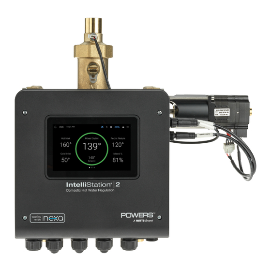
- Page 1 IOM-P-IntelliStation2 Installation, Operation, and Maintenance Manual A Smart and Connected Digital Water Mixing Solution IntelliStation 2 IntelliStation 2S...
-
Page 2: Table Of Contents
Contents Safety ....... . . Monitor Menu ..... . Attention Owners and Users . -
Page 3: Safety
Safety Attention Owners and Users Thank you for purchasing the Powers IntelliStation 2. This equipment will provide safe and ® productive operation as long as it is installed, set up, used, and serviced in accordance with the instructions in this Manual and is properly maintained. Owners and users of this equip☒ ment have the responsibility to make certain that this equipment is used properly and safely. -
Page 4: Reading And Understanding The Manual
Reading and Understanding the Manual TO AVOID DEATH, SERIOUS PERSONAL INJURY, PROPERTY DAMAGE, OR DAMAGE TO THE EQUIPMENT: • Read the Manual and all product • Keep the Manual available for easy labels and follow all safety and access and future reference. other information. -
Page 5: Compliance
Compliance The following statements apply to the IntelliStation® 2 IS2075VL, IS2100VL, IS2150VL, and IS2200VL • Installation of these valves MUST be performed by qualified technicians, including licensed electricians and plumbers, following all manufacturer’s instructions, complying with all local, state, federal and other governmental requirements, and with all building and construction codes and standards. -
Page 6: Specification
ICES RSS statement: This device complies with Industry Canada’s license-exempt RSSs. Operation is subject to the following two conditions: (1) This device may not cause interference; and (2) This device must accept any interference, including interference that may cause undesired operation of the device. - Page 7 Control Electrical Specification ITEM PARAMETER Input Power 120/240 V (ac) ±10%, 50/60 Hz, 17 W Pump Relays (Motor Load) 120/240 V (ac), 10/8 FLA, 50/48 LRA Alert Relay 120/240 V (ac), 5 A, 1/6 hp Isolation Valve Relays 24 V (ac/dc), 5 A, Resistive +5V Capacity 25 mA maximum, Resistive, Class 2 +20V Capacity...
-
Page 8: Diagrams
Diagrams Union/Street Connections (Press & Sweat Quick Response compatible) Temp Sensor ort for optional Pressure and Temp Sensing Electronic Actuator Mixing Valve Control Front View Side View Analog Temperature Mixing Outlet Sensor Digital Temperature & Pressure Mixing Outlet Sensor Digital Temperature & Pressure Cold Inlet Sensor Digital Temperature &... -
Page 9: Installing Intellistation 2
Installing IntelliStation 2 Installation of IntelliStation 2 is performed by the owner using qualified and licensed trades such as plumbers and electricians, following all local, state, federal and other governmental requirements, and all building and construction codes and standards. Step-by-step installation instructions depend upon the application and the configuration of the building’s water distribution system. -
Page 10: Mechanical
Mechanical Use appropriate rack mounting methods with consideration to weight of the system. Ensure the rack is mounted so that features of the system can be accessed easily for normal operation and maintenance. Allow for a minimum 8" to 14" on either side of the valve to allow for service. -
Page 11: Connections
Connections IntelliStation 2 can be installed with either of two different Union Connection fittings: Press-connect/Solder (standard) or NPT Threaded (separate purchase of the optional NPT kit required). Press-connect/Solder Best practice requires certain parts to be disassembled before soldering to avoid damaging O-rings and sensors. -
Page 12: Npt Threads
4. Properly identify the two inlet fittings and the mixing outlet fitting. The the inlet fittings and the outlet fittings are not the same. 5. Solder all connections in the correct locations with sensor ports facing toward the front of the control for accessibility. -
Page 13: Electrical
Electrical Cable connections are required from sensors and actuators to the control in order for the valve to function properly. Factory Wired Connections Cabling connects to the four ports on the side of the control: TEMP, ACTR, SENS, and ENCD. Temperature Sensor (TEMP) A quick response temperature sensor is included on the valve to measure and adjust the temperature at the mixed outlet position. - Page 14 Mixing Valve Actuator Encoder (ENCD) The mixing valve actuator includes an encoder for determining the position of the mixing valve. The control includes a keyed quick-connect 5 pin port for connecting the encoder cable labeled ENCD. (There is no low temperature actuator reset. A reset is not required for the actuator used with IntelliStation 2.) Mixing Valve Actuator Power (ACTR) A stepper motor drive in the control is used for regulating the actuator.
-
Page 15: Field Wiring
Field Wiring Use the following illustration and instructions to connect each segment of the potable water system to IntelliStation 2. See the appendix for additional detailed examples of pump wiring. Input Power (Terminals 1, 2, 3, 4) 1. Connect the 115 V (ac) line wire (L) to terminal 3. 2. - Page 16 For recirculation pump 1 1. Connect the power source (L) to terminal 5. 2. Connect a wire from terminal 6 to the pump L. 3. Connect a wire from the pump N back to the source neutral. For recirculation pump 2 1.
-
Page 17: Power Loss And Startup
Pump Proof (Terminals 25, 26) The control requires a closed switch or short for proof of flow. Up to 24 V (ac) can be passed through the switch. Connect the Pump Proof terminals 25 and 26 to the pump proof device. Building Management System (Terminals 27, 28, 29) A Building Management System (BMS) can be connected to the control for remote monitoring and adjustment capability. -
Page 18: Monitoring Intellistation 2
Monitoring IntelliStation 2 Always read the Manual and all product labels and follow all safety and other information. If you are ever uncertain about a particular task or the proper method of operating this equipment, ask your supervisor, consult this Manual, or Visit PowersControls.com. The control touchscreen operates much like a smartphone. - Page 19 Screen 3 Temperatures Hot, Cold, and Recirc Return temperatures (If option installed) and Mixing outlet setpoint and actual temperature. Swipe your finger left or right to view the main screens. Screen 4 System Inputs Water pressures and flow rates (If option installed) Swipe your finger left or right to view the main screens.
- Page 20 Screen 6 Mixed Outlet History Mixed outlet temperature history up to 24 hours Tap the mixed outlet circle on screen 1 for a graphical view of temperature relative to target setpoint over a time period. Tap to exit. Screen 7 Internet Connection Internet connection settings and status .
-
Page 21: Icons And Commands
Icons and Commands Tap an icon or command for information or to complete an action. Item Description Item Description DUAL Indicates messaging of an error or alert. Indicates by color whether valve sequencing Tap to see the last error message (Tap the is active or inactive X icon to exit the screen.) Blue, ON... -
Page 22: Remote Monitoring Intellistation 2 With Nexa
Enter the user-level pin number (10170). This unlocks the menu screens allowing you to make various adjustments to settings and turn on or off various options. (A custom passcode can be set through the Security menu.) Remote Monitoring IntelliStation 2 with Nexa IntelliStation 2 can be monitored remotely when you connect the equipment to the cloud- based Nexa application. -
Page 23: Menus And Programming
Menus and Programming Settings Menu When you select the Settings menu, the first seven submenus are displayed on the right of the screen. Use your finger to drag the submenu list up to see the last four submenus. Use the same technique to view all commands on a submenu. -
Page 24: Setup Wizard
Setup Wizard Hot water poses a danger of burning or scalding above 110 degrees Fahrenheit. Setting the mixing valve to temperatures over 110 Fahrenheit without the protection of additional point of use mixing valves could result in scalding at point of use fixtures such as faucets, sinks, tubs, showers, etc. - Page 25 Register and connect to Nexa or skip to the next screen. (To register and connect to Nexa, see “Remote Monitoring IntelliStation 2 with Nexa.” Complete steps 1 to 6 then return to complete the setup wizard.) Set the mixed outlet setpoint, from 60°F to 180°F. Set the recirculation return setpoint, from 60°F to 180°F.
- Page 26 Set the recirculation return differential, from 2°F to 50°F. Set the pump mode to Off, On, or Auto. (Digital Sensor Package (SENS) must be installed and enabled for access to the Auto pump mode setting.) Tap OK to close the setup wizard.
-
Page 27: Units Menu
When tapped, toggles to enable or disable connection to the Nexa platform Nexa Register Initiates Watts Nexa Registration Process for Device (Requires internet connection to be turned on) IP Configuration DHCP, Static DHCP allows for IP address to be assigned by server. -
Page 28: Bas Menu
BAS Menu Setting Range Description BAS Type Off, ModBus RTU, BACnet Sets the BAS communication type to be used MS/TP, BACnet IP Modbus Address 1 to 247 (Only available when ModBus RTU selected as BAS Type) Modbus Baud 9600, 19200, 38400, (Only available when ModBus RTU selected as BAS Type) Rate 57600, 76800, 115200... -
Page 29: System Menu
System Menu Submenu Setting Range Description Enable On or Off Allows the readings of the sensors to be displayed in Digital Sensor the system Inputs Screen if the digital temperature Package pressure sensor is installed Enable On or Off Allows the readings of the Mixed outlet flow sensor to be displayed in the System Inputs Screen if the flow sensor option is installed Make... -
Page 30: Alerts Menu
A Note on Pump Rotation For a pump rotation event to occur, both pumps must be set to Auto or to On, or to a combination of Auto and On. Regardless of the configuration the control monitors run time for each pumps and rotates from pump to pump based on the rotation time setting. Installation of Digital Sensor Package (SENS) is required and must be enabled along with Pump Rotation through Settings >... -
Page 31: Display Menu
Display Menu Setting Range Description Brightness 0% to 100% Sets brightness of the screen Clean Screen 10 second countdown Allows for screen to be temporarily locked for cleaning Reset Allows reset all of the control settings to factory defaults. Factory defaults (such as valve size) are set when the control is paired with the valve. - Page 32 If a schedule has not been set for the control, the following screen is displayed. From here, you can begin to program a schedule. Select the first set of days to be assigned the same scheduled times. Then, program the start and end of each occupied time frame of those days. Up to two occupied time frames can be programmed.
-
Page 33: Notifications Menu
Repeat the process for the remaining days until all days of the week have been programmed. To edit the schedule, scroll to the Device Schedule section. Tap the Pencil icon to edit the occupied and unoccupied times of weekdays. Tap the Calendar icon to change the set of days assigned the same scheduled times. -
Page 34: Sanitize Menu
Tap the error or alert notification entry to read the complete message. Sanitize Menu BEFORE starting the Sanitization function, make sure you are in full compliance with a safely and properly designed thermal sanitizing protocol, protecting end- users, facility employees or contractors, personnel performing the Sanitization, and bystanders from scalding, burning, thermal shock, or other hazards. - Page 35 You can manually begin a high temperature sanitization cycle from the Sanitize menu. Specify the temperature and duration of the cycle then launch the sanitization process. Set the duration of the cycle from 0 to 600 minutes. This time and temperature should be chosen based on your company’s Sanitation Protocol requirements, your plumbing systems characteristics, and sanitation validation data.
- Page 36 If at any time during the cycle you wish to discontinue the sanitization process, you can select End from the Sanitize menu. Or select STOP from the main monitoring screen on which the time remaining for the cycle is also displayed. Setting Range Description...
-
Page 37: Overrides Menu
Overrides Menu Allows for manual control of the actuator and mixing valve position. By changing the setting to manual, the status bar indicates manual mode and the main screen allows you to change the % Mixed of the valve. To return to automatic mode, change the setting back in the Overrides menu. -
Page 38: Monitor Menu
Monitor Menu Presents historical data on the system such as highest and lowest recorded readings, cycles, and runtimes based on the installed options. Tapping a blue reading allows you clear and restart. You can also restore all readings at once by tapping Reset at the bottom of the list. Warranty Menu Displays information of the devices warranty. -
Page 39: About Menu
About Menu Lists important details about the control. This information may be required when contacting Customer Support. Help Menu Scan the QR code to view or download product support documentation. -
Page 40: Troubleshooting
Troubleshooting RECOMMENDED: Complete all wiring to ensure trouble-free operation. Should an error occur, follow these steps: 1. Find If a banner is on the screen, it is indicating a problem on the system. 2. Identify Tap (upper right) to enter the menus and press notifications. The latest error notification is displayed at the top of the list. -
Page 41: Scheduled Testing, Inspection, And Maintenance
Scheduled Testing, Inspection, and Maintenance Testing/Inspection Periodic inspection and yearly maintenance by a licensed contractor is required. Corrosive water conditions and/or unauthorized adjustments or repair could render the valve ineffective for service intended. Need for Periodic Inspection/Maintenance: This product must be tested periodically in compliance with local codes, but at least once per year or more as service conditions warrant. -
Page 42: Errors And Alerts
Errors and Alerts Errors and alerts are listed when an error is detected or an alert initiated. Each error description may include a possible solution. Each alert description reports the conditions under which the alert is cleared. Control Memory Error A memory error has been detected. - Page 43 Internet Unavailable Error The control is unable to communicate to the Watts cloud through the internet. The error automatically clears when internet communications are established. You can also set the Connection Type to OFF to clear the error. To correct: 1.
- Page 44 Outlet Temperature Error The control detected an error with the temperature reading from the digital mixed outlet sensor. The control operates normally while this error is present. To correct, check the wiring and connections. If the wiring and connections are solid, then the sensor may require replacement. Contact Customer Support for further assistance.
- Page 45 Recirc Return Sensor Lost Error The control lost communication with the digital recirculation return sensor. The control operates normally while this error is present. However, if applicable, pump operation may be affected. To correct, check the wiring. If the wiring and connections are solid, then the sensor may require replacement. Contact Customer Support for further assistance.
- Page 46 Pump False Flow Error The control detected a flow proof signal after the delay time expired once the recirculation pump turned off� To correct, check the wiring between the flow proving device and the control� If the wiring and connections are solid, check the flow proving device and the pump�...
- Page 47 Encoder Error The control has detected an error with the stepper motor encoder� Valve position can no longer be accurately calculated� The valve continues to operate with limited functionality while this error is present� To correct, check the cabling between the encoder and the control� If the wiring and connections are solid, the encoder/stepper motor may require replacement�...
-
Page 48: Bas And Modbus Integration
BAS and Modbus Integration BAS Integration IntelliStation 2 provides user-directed control and monitoring of water distribution systems. It is the user’s responsibility to select and maintain water temperatures and pressures that are safe and appropriate for the water system users, guests and facility. The Sanitization mode is intended for use as part of a user-directed, controlled and supervised protocol that has been safely and properly designed. -
Page 49: Modbus ® Specification
Modbus Specification ® Communication Protocol Modbus over RS485 Physical Layer RS485 Two-Wire plus Signal Ground Baud Rate 2400, 9600, 19200, 38400, 57.6k, 115k) (default 19200 bps) Recommended Cable 18 AWG Shielded Twisted-Pair (STP) Transmission Mode Maximum Cable Length Without terminating resistors 115,200 baud -->... -
Page 50: Modbus Registers
Modbus Registers Read = R Read/Write = R/W System Status Registers Register Parameter Name Read/Write Units Type Format Range Mixed Outlet Temperature °F Input -31 to 266 Recirc Return Temperature °F Input 32 to 212 Hot Inlet Temperature °F Input 32 to 212 Cold Inlet Temperature °F... -
Page 51: Bacnet Integration
BACnet Integration IntelliStation 2 provides user-directed control and monitoring of water distribution systems. It is the user’s responsibility to select and maintain water temperatures and pressures that are safe and appropriate for the water system users, guests and facility. The Sanitization mode is intended for use as part of a user-directed, controlled and supervised protocol that has been safely and properly designed. - Page 52 Supported BIBB (Annex K) Name DS-RP-B Data Sharing-ReadProperty-B DS-RPM-B Data Sharing-ReadPropertyMultiple-B DS-WP-B Data Sharing-WriteProperty-B DM-DDB-B Device Management-Dynamic Device Binding-B DM-DOB-B Device Management-Dynamic Object Binding-B DM-DCC-B Device Management-Device Communication Control-B Note: Device communication control password is “Powers1164”. Segmentation Capability Supported Able to transmit segmented messages Able to receive segmented messages Standard Object Types Supported Creatable...
-
Page 53: Bacnet Objects
BACnet Objects BACnet Analog Parameters Analog Input Object = AI Analog Value Object = AV Read = R Read/Write = R/W Analog Input Objects Data Read/ Range / Name Description Units Type Write Value Mixed Outlet Mixed Outlet Temperature °F -31 to 266 Temperature Recirc Return... -
Page 54: Bacnet Binary Parameters
BACnet Binary Parameters Data Read/ Range / Name Description Units Type Write Value Recirc Pump 1 Recirculation Pump 1 0=Off, Status 1=On Recirc Pump 2 Recirculation Pump 2 0=Off, Status 1=On Isolation Valve Isolation Valve Status 0=Closed, 1=Open BACnet Troubleshooting If there is no or intermittent communication, check the following: •... - Page 55 Code Description Ethernet Disconnected Error Wi-Fi Disconnected Error Wi-Fi Invalid Password Error DHCP Address Error Internet Unavailable Error Nexa Error Mixed Outlet High Temp Alert Mixed Outlet Low Temp Alert Hot Inlet High Temp Alert Hot Inlet Low Temp Alert Hot Inlet High Pressure Alert Hot Inlet Low Pressure Alert Cold Inlet High Pressure Alert...
-
Page 56: Appendix: Supplemental Wiring Diagrams
Appendix: Supplemental Wiring Diagrams Single Valve, Single 115 Vac Recirculation Pump... -
Page 57: Single Valve, Dual 115 Vac Recirculation Pumps (Direct)
Single Valve, Dual 115 Vac Recirculation Pumps (direct) -
Page 58: Single Valve, Dual 115 Vac Recirculation Pumps
Single Valve, Dual 115 Vac Recirculation Pumps... -
Page 59: Dual Valve, Dual 230 Vac Recirculation Pumps
Dual Valve, Dual 230 Vac Recirculation Pumps... -
Page 60: Single Valve, Single 115 Vac Recirculation Pump, Grundfos Flow Meters
Single Valve, Single 115 Vac Recirculation Pump, Grundfos Flow Meters... -
Page 61: Single Valve, Single 115 Vac Recirculation Pump, Keyence Flow Meters
Single Valve, Single 115 Vac Recirculation Pump, Keyence Flow Meters... -
Page 62: Dual Valve, Isolation Valve
Dual Valve, Isolation Valve... - Page 63 COMPUTER SYSTEM, NETWORK AND DATA DISCLAIMER: IntelliStation 2 receives stores and displays data concerning your water distribution system, performs functions based upon owner/user data input and selections, and can be remotely programmed and utilized with specified and compatible building automation systems. AS SUCH, POWERS MAKES NO EXPRESS OF IMPLIED WARRANTY, INCLUDING WARRANTIES OF MERCHANTABILITY AND FITNESS FOR A PARTICULAR PURPOSE, REGARDING COMPATIBILITY WITH OTHER TECHNOLOGIES, HARDWARE, SOFTWARE, NETWORK OR SYSTEMS, THE ACCURACY OR COMPLETENESS OF...
-
Page 64: Limited Warranty
Company from time to time, the Warranty Period will be extended to a period of three (3) years from the date of original shipment. 2. If you connect the Product to the Watts Nexa™ platform, the Warranty Period will be extended to a period of five (5) years from the date of original shipment.
Need help?
Do you have a question about the POWERS IntelliStation 2 and is the answer not in the manual?
Questions and answers