Table of Contents
Advertisement
Quick Links
Operation and Maintenance
Manual
Pre/Post-vacuum Class B
Table–top Autoclave
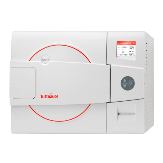
Model Elara11
Cat. No. MAN205-0497002EN Rev. H
Tuttnauer Co. Ltd., Har Tuv Industrial zone B P.O.Box 170, Beit Shemesh
9910101, Israel Tel: 972 2 9904611, Fax: 972 2 9904730
Tuttnauer U.S.A. Co, Ltd. 25 Power Drive Hauppauge, NY, 11788, USA.
Tel (631) 737 4850, (800) 624 5836, Fax: (631) 737 0720
Advertisement
Table of Contents

Subscribe to Our Youtube Channel
Related Manuals for Tuttnauer Elara11


Summary of Contents for Tuttnauer Elara11
- Page 1 Model Elara11 Cat. No. MAN205-0497002EN Rev. H Tuttnauer Co. Ltd., Har Tuv Industrial zone B P.O.Box 170, Beit Shemesh 9910101, Israel Tel: 972 2 9904611, Fax: 972 2 9904730 Tuttnauer U.S.A. Co, Ltd. 25 Power Drive Hauppauge, NY, 11788, USA.
-
Page 2: Table Of Contents
Table of Contents Paragraph Page No. GENERAL ..........................3 1.1. US O ..........3 ANUFACTURER AND FFICIAL ORRESPONDENCE NFORMATION 1.2..........................3 NTENDED 1.3......................... 3 NTENDED SERS 1.4......................... 3 NCOMING NSPECTION 1.5..........................4 ARRANTY 1.6....................... 4 ARRANTY TATEMENT 1.7. - Page 3 5.3................60 YCLE ARAMETERS FOR USTOM ROGRAMS PRINTER ..........................69 6.1........................69 RINTER UTPUT 6.2........................71 RINTER ANDLING INSTALLATION INSTRUCTION ..................74 7.1......................74 IFTING AND ARRYING 7.2....................... 74 NPACKING THE AUTOCLAVE 7.3..........................74 LACING 7.4.
-
Page 4: General
USA. Tel: (631) 737 4850, (800) 624 5836, Fax: (631) 737 0720 1.2. Intended Use The Elara11 tabletop autoclave is designed for the sterilization of medical and surgical goods such as wrapped and unwrapped solid, hollow, and porous loads used in healthcare facilities (e.g., hospitals, nursing homes, extended care facilities, freestanding surgical centers, clinics, and medical &... -
Page 5: Warranty
HEPA filters (they are considered wear items). Tuttnauer warranties the chamber for a period of ten (10) years against defects in materials and workmanship. This warranty does not include installation or operator instruction which are covered in this manual for your convenience, or which can be provided by your dealer. -
Page 6: Safety Instructions
Tuttnauer USA Co. Do not attempt to service this instrument yourself. Tuttnauer USA Co., Ltd., 25 Power Drive Hauppauge, NY 11788, USA Tel: (800) 624 5836, (631) 737 4850, Fax: (631) 737 0720 e-mail: info@tuttnauerUSA.com. - Page 7 8. Verify once again that you have chosen the appropriate sterilization program and the water reservoirs are full. 9. Do not place your hand or head, etc. above the door while opening, as hot steam is escaping the chamber. 10. Do not stand near the back panel of the autoclave while operating, as the pressure safety valve may release steam.
-
Page 8: General Information
General Information This autoclave is an electrically heated sterilizer using steam as a sterilizing agent. The Elara11 is designed as a Type B sterilizer in accordance with EN13060. The Elara11 is a pre/post-vacuum sterilizer which uses vacuum pulse technology for removing air from the chamber at the beginning of the cycle and moisture from the instruments at the end of the cycle. - Page 9 Bowie and Dick 273°F 2 min The Elara11 is validated for use in sterilizing lumened devices of no longer than 230mm and no smaller than 3.4mm for sterilization programs 2 and 4. The Elara11 is validated for use in sterilizing fabric packs/textiles for sterilization programs 2 and 4.
- Page 10 A printer is standard on the autoclave. The printer prints the preset and actual parameters of the cycle (temperature, time, and pressure). The Elara11 also features built in memory to record up to 100 sterilization cycles. These can be reprinted on the printer or exported to a USB device to be transferred to a PC.
-
Page 11: Operating Conditions
Operating Conditions This device is for indoor use only! The minimum counter depth for the Elara11 is 24 inches. Counter tops or slide-outs need to have a minimum capacity of 275 pounds. The sterilizer should be loaded only with autoclavable material! Minimum room ventilation shall be 10 cycles per hour. -
Page 12: Overall Dimensions
1.11. Overall Dimensions Page 11... -
Page 13: Front View
1.12. Front View Description Description Door microswitches Keypad Autoclave door Printer cover Autoclave outer cover Door opening grip Mineral-free water reservoir Plastic door cover Water reservoir fill and level gauge Chamber and steam generator Autoclave Leg safety valves (inside the reservoir) Wastewater reservoir Wastewater drain Display... -
Page 14: Rear View
1.13. Rear View No. Description No. Description Mineral-free water reservoir RJ45 network port Wastewater reservoir Jacket cut-off thermostat Ventilation grills Generator cut-off thermostat Air filter service cover Main power electric cable socket Wastewater outlet to drain Warning! Mind the Power Socket. Keep it and its vicinity dry. Danger of electrocution. -
Page 15: Specifications
1.14. Specifications Property ELARA11 Shipping weight 171 lbs (78 kg) Maximum weight with instruments full 194.89 lbs (88.4 kg) reservoirs and generator W 28.4” * L 32” * H 27.5” Shipping dimensions (width/height/depth) (W 72cm * L 81.2cm * H 70cm) Shipping volume 14.47 cu ft. -
Page 16: Autoclave Electrical Data
1.16. Autoclave Electrical Data Property Value Total Power 2300W Voltage 1 or 2 phase, / 230VAC ±5%, 60Hz Amperage Protection against electrical IEC 61010-1 shock Mains supply fluctuation +/- 5% Frequency (Hz) 60Hz Electrical Circuit Dedicated electrical circuit Recommended circuit breaker 1.17. -
Page 17: Stickers Description
• Door is made of stainless steel 316. • Trays are made of stainless steel 304. • Water reservoir is made of polyethylene. • Door handle and door cover are made of hard plastic material, which is safe to touch and thermo-insulated. 1.20. -
Page 18: Symbols Description
1.21. Symbols Description Manufacturer Year of Manufacturing Medical Device Model Number Serial Number Consult the Operation and Maintenance Manual (User Manual) before use Keep away from sunlight and protect from heat. For Indoor Use Only Keep dry Disposal according to electronic scrap ordinance Page 17... - Page 19 This side up (during transport and shipment) Fragile (during transport and shipment) A warning or precaution as detailed in the Operation and Maintenance Manual (User Manual) Caution! Hot Surface Caution! Hot steam Protective earth (Ground) Page 18...
-
Page 20: Water Quality
1.22. Water Quality The distilled or mineral-free water supply shall be according to the table below: Suggested maximum limits of contaminants in water for steam sterilization per EN13060 Substance Feed Water Condensate ≤ 10 mg/l ≤ 1.0 mg/l Evaporate residue ≤... -
Page 21: Directives And Standards
1.23. Directives and Standards Every autoclave meets the provisions of the following Directives and is in compliance with the following Standards: Medical Device Directive 93/42/EEC as amended by 2007/47/EC Medical Device Single Audit Program – (MDSAP) ISO 9001: Quality Management System Quality Management System –... -
Page 22: Control Panel
CONTROL PANEL Visual Information Center Control Center Data Center Description Display On/off switch and circuit breaker Keypad USB Port Printer (Standard) Page 21... -
Page 23: Description And Functions Of The Front Panel
2.1. Description and Functions of the Front Panel The front panel is composed of 3 sections (see picture on previous page): Visual Information Center Control Center. Data Center 2.2. Visual Information Center The information center contains the display which is an LCD panel used to display the current status of the autoclave and any Operational Messages or Error Messages. -
Page 24: The Control Center
2.3. The Control Center The Control Center contains the ON/OFF switch/Circuit Breaker and the Keypad The keypad consists of 3 keys as described below: UP key This key has the following functions: • In the main screen: This key enables the operator to browse through the cycles. •... -
Page 25: Data Center
The USB drive must be FAT formatted. • The network port (located on the rear of the unit) can be used to connect to a local network and download information to Tuttnauer’s R.PC.R software. The RPCR software has been developed especially for the Tuttnauer autoclaves and is an excellent report generating tool. -
Page 26: Displayed Operational Messages / Symbols
2.6. Displayed Operational Messages / Symbols Message / Message / Symbol Required Action Symbol Name Description This symbol is displayed Close the door. when the door is open. This message is displayed in stand-by Close the door to perform a new when the door is "Door is open"... - Page 27 Drain the wastewater reservoir by This symbol is displayed plugging the included drain tube when the wastewater into the wastewater drain. (see reservoir is full. front view) This symbol is displayed, and the cycle will not start if the steam Wait until the pressure in the pressure in the generator reaches the required...
-
Page 28: View Screens
VIEW SCREENS During the cycle, the screen will change to let you know how the cycle is progressing. The following screens are a representation of what will be seen during a cycle. 3.1. Screens showing a successfully completed cycle 1. System Ready 2. -
Page 29: Screens Showing Aborted Cycles Aftera Completed Sterilization Stage
3.2. Screens showing aborted cycles AFTER a completed sterilization stage The sterilization phase ended successfully – the cycle was aborted and the reason for the failure is displayed. When the sterilization portion of the cycle is successful the display remains white even though the cycle was aborted. -
Page 30: Screens Showing A Failed Cycle Before Completing The Sterilization Stage
Note: The user will have to press the START/STOP key, after the mandatory 1-minute drying, to clear the message and unlock the door. 3.2.3. Screens showing a High-Pressure Failure AFTER a completed sterilization stage The sterilization stage ended successfully, however the chamber indicated that there was high pressure during the exhaust phase. - Page 31 Cycle failed message Reason of failure The screen color changed from white to Warning symbol yellow The next two scenarios show examples of possible error messages: 3.3.1. Screens showing a ailure because of a Heat Time Error The machine was not able reach the proper temperature. This resulted in the following sequence of screens showing the reason for the aborted cycle.
- Page 32 3.3.2. Failure due to Cancellation by user BEFORE completing the sterilization stage Note: The user will have to press the START/STOP key, after the mandatory 1-minute drying, to clear the message and unlock the door. Page 31...
-
Page 33: Sterilization Programs
STERILIZATION PROGRAMS The control system incorporates a safety feature that prevents changing programs if the door is closed. This protection is intended to prevent running an inappropriate program if the autoclave is loaded, but the cycle is not immediately started. If the operator for example inserts the load into the chamber, closes the door and leaves the room and another operator/user tries to change the program, the operator/user will not be able to do this unless the door is... - Page 34 During the process, the various stages of the cycle will be displayed on the screen. The stages names are as follows: Starting Pulse L Pulse H Heating Sterilization Exhaust Drying Ending The user should use only those sterilizer accessories (Biological Indicators, Chemical Indicators, etc.) that have been cleared by the FDA for the specific cycle time and temperature of this device.
-
Page 35: Program 1: Unwrapped Instruments
4.1. Program 1: Unwrapped Instruments For unwrapped instruments and materials, when the instrument manufacturer recommends autoclaving at temperatures of 273.2°F (134°C) and no drying stage is required (1-minute drying is still required to remove residual steam from the chamber). Nominal parameters default settings Sterilization temperature: 273.2°F (134°C) Sterilization time: 4 minutes. -
Page 36: Program 2: Wrapped Instruments
4.2. Program 2: Wrapped Instruments For wrapped instruments, pouches, and materials, when the instrument manufacturer recommends autoclaving at temperatures of 273.2°F (134°C) with a drying stage. Nominal parameters default settings Sterilization temperature: 273.2°F (134°C) Sterilization time: 4 minutes Drying time: 20 minutes (may be increased by the operator (see sec. 5.1.1), other parameters are set and cannot be altered). -
Page 37: Program 3: Unwrapped Delicate Instruments
4.3. Program 3: Unwrapped Delicate Instruments For unwrapped delicate instruments, when the instrument manufacturer recommends autoclaving at temperatures of 249.8°F (121°C) and no drying stage is required (1-minute drying is still required to remove residual steam from the chamber). Nominal parameters default settings Sterilization temperature: 249.8ºF (121ºC) Sterilization time: 20 minutes. -
Page 38: Program 4: Wrapped Delicate Instruments
4.4. Program 4: Wrapped Delicate Instruments For wrapped Handpieces when the instrument manufacturer recommends autoclaving at temperatures of 249.8°F (121°C) with a drying stage. Nominal parameters default settings Sterilization temperature: 249.8ºF (121ºC). Sterilization time: 20 minutes. Drying time: 20 minutes (may be increased by the operator (see sec. 5.1.1), other parameters are set and cannot be altered). -
Page 39: Program 5: Calibration Cycle
4.5. Program 5: Calibration cycle This program is only for use by a technician with the proper test equipment to aid in calibrating the autoclave. This is a shortened cycle with a long sterilization phase at 273.2°F (134°C) and no drying. (1- minute drying is still required to remove residual steam from the chamber). -
Page 40: Program 6: Extra Drying Time
4.6. Program 6: Extra Drying Time For all loads when the load requires additional drying after the cycle is completed. Nominal parameters default settings Drying time: 5 minutes (may be changed by the operator (see sec. 5.1.1)). Operations Sequence Drying for 5 minutes. Page 39... -
Page 41: Program 7: Vacuum Test
4.7. Program 7: Vacuum Test Vacuum is produced in the chamber, down to P1=2.47psi (0.17bar). At this stage all the valves close. The autoclave remains in this stage for 5 minutes. This period enables the condition in the chamber to reach equilibrium. -
Page 42: Program 8: Bowie And Dick
4.8. Program 8: Bowie and Dick • Air-removal stage: a series of vacuum pulses are performed. • Heating stage: steam is injected into the chamber, from the steam generator, until the sterilization temperature is reached. • Sterilization phase: temperature and pressure are maintained constant at the pre-set level during the sterilization time. -
Page 43: Checking And Changing Parameters And Other Data
CHECKING AND CHANGING PARAMETERS AND OTHER DATA This section shows how to access system data and modify parameters. The Cycle Parameters directory containing parameters for controlling the sterilization process is locked for programs 1 thru 4 and not available for modification from the default values (except for drying). Program 5 is a calibration program for use by a technician and all parameters are locked. -
Page 44: Quick Options Directory
5.1. Quick Options Directory To take advantage of the system features it is necessary to access the programming mode. Some subdirectories enable the operator to see and change an individual cycle’s parameters. Therefore, it is necessary to choose the required cycle before entering the programming mode. Enter the programming mode by pressing the UP and DOWN keys simultaneously for 1-2 seconds. - Page 45 5.1.2. Export to USB Note: The USB flash drive needs to use FAT formatting. Scroll up or down the list and press the START/STOP key to select. Export current version to USB Accessing the Export current version feature allows the operator to export the machines current application for evaluation by a technician.
- Page 46 100 cycles to a USB device for evaluation or digital storage. Cycle data is exported in individual text file format (.txt) for viewing on a PC or with Tuttnauer’s R.PC.R software. Exporting the cycle history will not automatically delete the cycle history.
- Page 47 Insert the USB device into the USB socket located behind the printer door (see sec. 2.4) Move the cursor to select the number of cycles to export. Press the START/STOP key. The following screen will be displayed. 5.1.3. Print cycles Select this option and the following screen will be displayed.
- Page 48 5.1.4. Version information This subdirectory allows viewing of the current version of software running the machine. Select this option and the following screen will be displayed. Software Serial Model version number Name 5.1.5. Start cycle by clock This option allows scheduling the selected cycle to start at a later time (The maximum possible delay is 24 hours).
- Page 49 Enabling the Start Cycle By Clock Select the cycle to be scheduled from the Main. Screen before enabling this option. Set the start time by using the UP and DOWN keys to change the blinking digit. Use the START/STOP key to move to the next digit. Use the START/STOP key to move the cursor to Enable.
- Page 50 5.1.6. Set date and time Note: It is important to set the date and time when setting up a new machine for the first time. The internal battery is turned off for shipping. Setting the date and time will restart that battery. Note: Failure to set the Date and Time will cause a Time Error and the unit will not run properly.
- Page 51 To set the date use the UP and DOWN keys to change the blinking digit. Use the START/ STOP key to move to the next digit. When all changes are completed, use the START/ STOP key to move to SET, then use the UP or DOWN key to save the new date and time. Setting the Date and time will cause the autoclave software to automatically reload.
-
Page 52: Main Menu
To increase or decrease the right digit, press the UP or DOWN keys. Change the code to 0001 and move the cursor to SET b y p r e s s i n g t h e S T A R T /STOP k e y f o u r times. When SET is blinking, press the UP or DOWN key to enter the MAIN MENU screen. - Page 53 the cursor to EXIT and then press START/STOP. An explanation of the various directories, subdirectories and parameters can be found on the following pages. 5.2.1. Cycle Parameters This directory allows for the modification of parameters for custom programs only, except for the drying parameter in programs 1 thru 4 and 6 (see section 5.3 ).
- Page 54 Modifying a system parameter Every parameter can be changed as follows: Select any program to modify the System Parameters. Enter the programing mode by pressing the UP and DOWN keys simultaneously for 1-2 seconds and then release. Login using the User code 0001 Select System Parameters from the Main Menu and press the START/STOP key.
- Page 55 Use the UP or DOWN keys to move to the appropriate parameter from the system parameters screen. Use the START/STOP key to select this parameter. The set parameter screen will appear. The Set parameter screen shows the name of the parameter to be changed;...
- Page 56 5.2.3. Maintenance This directory offers the following three options. These options apply to all programs. • Reset atmospheric pressure. • Printer test • Print all gain and offset. Modifying a maintenance parameter Select any program from the Main Screen to access the Maintenance options.
- Page 57 The following screen will appear: Use the UP or DOWN keys to move to the appropriate option from the maintenance screen. Use the START/STOP key to select this option. The screen for that option will appear (see the screens for each option in the following sections).
- Page 58 To exit this screen, press the START/ STOP key. 5.2.3.2. Printer Test This option enables the operator to test the printer. The printer will provide the following print out: Page 57...
- Page 59 When the printer has finished, the following screen will be displayed: To exit this screen, press the START/STOP key. 5.2.3.3. Print All Gain and Offset This option allows for printing all the gain and offset values. This information is for use by a factory engineer. The printer will provide gain and offset for the following: •...
- Page 60 The following screen will be displayed: To exit this screen, press the START/ STOP key. 5.2.4 Advanced Options This directory offers the following two options. These options apply to all programs. • Set Temperature Units – allows the selection of either °F or °C. •...
-
Page 61: Cycle Parameters For Custom Programs
5.3. Cycle Parameters for Custom Programs The Elara11 offers the user the ability to create a custom program for any items where the preinstalled programs are not appropriate. This directory enables the operator to see and change all the cycle parameters for that custom program. - Page 62 Dry Time Dry Heat On 1 Dry Heat Off 1 Dry first stage time Drying Dry Heat On 2 Dry Heat Off 2 Additional Dry Time Ending End Temperature Global Jacket Temperature 5.3.1 Modifying a parameter for a Custom Program In the following example one of the preinstalled programs was duplicated and it was named Custom A.
- Page 63 4. Login using the User code 0001. Select Cycle Parameters (Custom A) from the Main Menu. Use the UP or DOWN keys to move to the Create Pulse subdirectory as shown in the table in sec. 5.3.2 Pressing the Page 62...
- Page 64 START/STOP key will allow the user to enter that subdirectory. Pressing the START/STOP key again will select the individual parameter for modification. The Set Parameter screen will appear as shown with the current parameter setting highlighted. This screen is representative of a typical Set Parameter screen. The Set Parameter screen shows the name of the parameter to be changed;...
- Page 65 without changing the parameter. The custom programs are not FDA cleared and it is the user’s responsibility to validate any custom cycles. Spore testing is your only assurance of complete sterilization. 5.3.2 Table of Parameters This option is only available for a Custom program. This table describes the function of each of the parameters that control the different parts of the sterilization cycle.
- Page 66 steam. Purge Temperature at which °C temperature purge stage can start. Defines the number of Pulse A pulses in the first Whole Count pulse group (group A) Number 0-10 Defines the additional time that the top exhaust valve will remain open after reaching the pressure set by Pulse A Stay...
- Page 67 Defines the additional time that the top exhaust valve will remain open after reaching the pressure Pulse C Stay set by the Pulse C low Time Pressure parameter in Seconds 1-100 pulse group C. Defines the pressure that the top exhaust 0.73 –...
- Page 68 Defines the temperature that Sterilization needs to be 212 ºF- Temperature maintained during °F 284 ºF 0.5° sterilization. Defines the length of time the sterilization temperature and Sterilization pressure must be Minutes 0-9999 Time held. This parameter allows four choices; 1.
- Page 69 The total drying cycle can be divided into two stages. This parameter defines the length of the first stage. The second Dry First stage will start at the Stage Time end of the first and Minutes 0-120 last until the end of the total drying.
-
Page 70: Printer
PRINTER 6.1. Printer Output The printing is on thermal paper with 24 characters per line and contains the following information: • Date: • Time: • Ser. Num: • Model: • Software Version: • Cycle Num: • Cycle Name: • Ster Temp: •... - Page 71 during drying E 00:23:43 224.0 The time, temperature, and pressure during exhaust 29.8 E 00:22:08 273.5 Ending of the timer verification of the CLK 2 00:22:08 sterilization phase. The difference in CLK 1 00:22:08 clocks cannot exceed 3 seconds. 29.86 S 00:22:06 273.5 The time, temperature, and pressure...
-
Page 72: Printer Handling
Sterilization temperature for the selected program Unwrapped Instruments Cycle name Cycle Num: 000001 Cycle number Software vers: 2.0.3.97 Software version Version: Model: Elara11 Model name Ser. Num: 000000000001 Model Serial number Time: 08:33:29 Time of starting cycle Date: 9/FEB/2010 Date of starting cycle -------------------------------------------------------------... - Page 73 6.2.2. Installing printer paper Printer model PLUS II front view (see Fig. 1) 1-Paper mouth 2-Power On Led 3-Open Button (for opening the paper roll compartment) 4-Paper Feed key 5-Paper roll compartment 6-Paper end of roll sensor Fig. 1 Open the printer's cover door (3) by pulling it at the left bottom corner (2) (see Fig.
- Page 74 Place the paper roll making sure it unrolls in the proper direction as shown (see Fig. 3/2). The paper should roll off the top of the roll. Hold the loose end of the paper with one hand and re-close the cover with the other hand as shown (see Fig.
-
Page 75: Installation Instruction
an electric shock, which may lead to fire or personal injury . Use caution when cleaning the printer or autoclave. Splashing water, cleaning solution or other liquids into the printer can cause fire or electrical shock . Never touch the thermal head immediately after printing as it becomes very hot. -
Page 76: Electrical
Check and verify that the counter carrying the autoclave is a rigid and leveled surface and can carry a load of 275lbs (125kg). Attention: The ELARA11 is not designed for use on any standard slide out shelf. If it is necessary to use a slide out shelf, it must be tested and/or rated for 275lbs (125kg) or more. -
Page 77: Setup
7.5. Setup Your new Tuttnauer Autoclave was programmed and tested at the factory and requires a minimum of setup. Make sure the counter is level and sturdy (see sec. 7.3 above). Make sure all the feet are on the autoclave and none of them has been lost. -
Page 78: Filling The Mineral-Free Water Reservoir
7.6. Filling the Mineral-Free Water Reservoir. Use only steam distilled water having the characteristics described in sec. 1.22 Open the door (1). The autoclave needs to be on for the door to open. Pour steam distilled water, gently, into the front funnel (2) until it reaches the top of the blue area (3) on the level gauge. - Page 79 CAUTION! Under no circumstance should water be filled above the safety valve holder. In case more water is accidentally filled above the blue area or safety valve, decrease the water level by draining the reservoir before starting a cycle (see sec. 10.4). Note: This reservoir is designed with an overflow and filling the reservoir above the safe level as indicated on the Front Fill Funnel will cause excess water to spill out below the machine onto the counter.
-
Page 80: Preparation Before Sterilization
Notes: To protect sensors at the back bottom of the chamber, the rack of the Elara11 is designed with stops for the bottom tray. It is normal for the bottom tray to be closer to the door than the other trays. - Page 81 When using a paper / plastic bag, the plastic side should always be up. Do not stack pouches. It is recommended that a pouch rack such as the Tuttnauer Pouch Rack be used to ensure proper steam penetration and adequate drying. Surfaces that are hidden because the items are being stacked will not be exposed to the steam and will not be sterilized.
- Page 82 There should be about ½” (1.25cm) between cassettes or packs for proper steam circulation. Cassettes in an ELARA11 should be sterilized in a vertical position (see the figure below). To adjust the rack for vertical sterilization of cassettes remove the trays and gently squeeze the sides of the rack inward and at the same time rotate the rack into a vertical position.
- Page 83 Small packs can be placed directly on the tray in an upright position. They should not be touching each other or the Chamber walls. There should be about ½” to 1” between packs for proper steam circulation. Place a sterilization indicator on each tray and/or inside each wrapped cassette.
-
Page 84: Operating Instructions
OPERATING INSTRUCTIONS It is recommended to perform B&D test cycle (see 4.8) at the beginning of each working day. Turning on the autoclave Plug the power cord into the back of the autoclave and into the wall outlet. Turn on the rocker switch mounted on the side of the front panel. 9.1. -
Page 85: Wastewater Reservoir
9.2. Wastewater Reservoir The Elara11 has two reservoirs, a mineral free reservoir for clean steam distilled water and a wastewater reservoir for water that has gone through the sterilization process. When the wastewater reservoir is full, the symbol displayed. This situation is normal; however, the operator cannot run a new cycle before draining the waste water reservoir (see10.4). -
Page 86: Adding Additional Drying Time
See sec. 5.1.1 for detailed instructions on adding extra drying time. Tuttnauer strongly suggests that each user/operator learn how to arrange the load and apply additional drying time. This will ensure that your sterilizer provides efficient drying of the pouched and/or wrapped instruments used in your office. - Page 87 Tuttnauer o f using a combination of trays and racks for sterilizing heavy or diverse loads. The Elara11 is supplied with 5 wire trays. NOTE: The Elara11 can accommodate 2 pouch racks. Elara11 1. Ensure that the correct sterilization program is selected: •...
-
Page 88: Cycle Description
• The program can only be changed when the door is open. 2. If needed additional drying time can be added at this time (see Sec. 5.1.1). Note: Pushing the bottom tray all the way back will cause it to interfere with the chamber sensors. -
Page 89: Extra Drying Time
9.7. Extra Drying Time If you see that additional drying is needed, with the door open use the Up / Down keys to select Extra Drying Time, then close the door and press the Start/Stop button to run the Extra Drying Time cycle (see sec.4.6). - Page 90 failure. (See sec. 3.3 ). If the cycle is manually aborted after the sterilization stage is completed, the screen will remain white with the message “Cycle Ended” and a second message stating the reason for the failure. (See sec. 3.2.) There is a mandatory 1 minute of drying before the door can be opened.
-
Page 91: Preventive And Scheduled Maintenance
Should the need arise or the instructions in this section indicate, technical assistance or a service technician can be requested by either calling your dealer or Tuttnauer USA. 10.1. Daily by the Operator Turn the unit on momentarily to allow the door to be opened. -
Page 92: Weekly By The Operator
10.2. Weekly by the Operator • Clean the outer parts of the autoclave with a soft cloth. • Replace mineral free water in the reservoir. • If the autoclave is only used occasionally, drain the water from the mineral free water reservoir once a week, and refill with fresh distilled water (see 7.6). -
Page 93: Periodically By The Operator
10.3. Periodically By the Operator Caution! Make sure the autoclave is not hot before cleaning it Once a month, check both safety valves. Once a month clean the strainer as per para. 10.6. Cleaning frequency may be reduced according to experience. Replace the air filter, every 6 months or after 1000 cycles (whichever comes first) according to 10.5. -
Page 94: Replacing The Air Filter
10.5. Replacing the Air Filter Cautions! Carefully un-pack the new filter and examine it for any signs of damage. Remove any protective packaging before inserting the filter into place. To “break” the vacuum, at the end of the dry phase, filtered atmospheric air is allowed to enter the chamber via a solenoid valve. - Page 95 Insert the filter into the autoclave and secure the filter cover by turning it a ¼ turn clockwise. Verify that the tube has not been kinked and that the cover is fastened securely. Note: It is recommended to replace the air filter, every 6 months or after 1000 cycles (whichever is the shorter period).
-
Page 96: Replacing The Door Gasket
10.6. Replacing the Door Gasket To avoid injuries, replace the gasket while the autoclave and autoclave door are cold. Pull off the gasket from the door groove and install the new gasket referring to the directions below. Pull off the gasket from the groove. Clean the groove of any remnants of the old gasket (use a plastic scraper and plain water as needed). - Page 97 Note: It is necessary to use a silicone based lubricant such as Würth Silicone Lubricant or Dow Corning 111, when installing the door gasket. CAUTION! If insufficient lubricant is applied - replacing the gasket will be difficult. If excess lubricant is applied, the gasket will 'spring' out of the groove.
-
Page 98: Checking The Safety Valve
Caution! Make sure the gasket sits evenly without waves, humps, or cavities. If the door gasket is not perfectly smooth it will not seal the chamber properly This drawing shows the correct direction of the gasket. Gasket Door 10.7. Checking the Safety Valve There are two safety valves located in the mineral free water reservoir. - Page 99 Operate the sterilization cycle according to the manual, but with no instruments. Allow a pressure of approximately 29 Psig (300KPA) to build up in the chamber. Remove water reservoir cover (1). CAUTION! The next step will expose you to hot steam. To avoid being burned by hot steam, keep all body parts away from the steam flow.
-
Page 100: Cleaning Water Strainer
10.8. Cleaning water strainer CAUTION! Do not touch the strainer or chamber shortly after operation as they will be very hot. Touching the hot strainer may cause severe injuries. If this maintenance operation is performed while the strainer is hot, use heat resistant gloves to avoid injuries. -
Page 101: Emergency Opening Of The Door
10.9. Emergency opening of the door Caution! This option is for emergency cases only! Before opening the d o o r , a l w a y s make sure that there is no pressure in the chamber and the electric cord is disconnected (See above). -
Page 102: Troubleshooting
Only technical personnel having proper qualifications and holding technical documentation (including a technician manual) and adequate information are authorized to service the apparatus. For technical assistance call your dealer or Tuttnauer USA Problem/ Error Message / Symbol Description... - Page 103 Problem/ Error Message / Symbol Description Corrective Action Message Wait until the chamber reaches the normal "Chamber This message is displayed if the pressure range. pressure not pressure in the chamber is higher The atmospheric in range" or lower than the normal range. pressure parameter may need to be set.
- Page 104 Problem/ Error Message / Symbol Description Corrective Action Message This message is displayed if the Perform a new cycle. The system cannot reach the required chamber may be "Heat Time temperature, in the chamber, overloaded, remove some Error (Keep)" during the optional "Keep Heat" material from the stage, within the preset time.
- Page 105 Problem/ Error Message / Symbol Description Corrective Action Message "RTC Error - Set Current Date and Please Set This message is displayed to set Time. Current Date the date and the time. If the problem persists, and Time" call the technician. The Date and Time have not been Set current Date And set.
- Page 106 Problem/ Error Message / Symbol Description Corrective Action Message Fill the mineral free water This message is displayed if the "Mineral free reservoir. If the reservoir water level electrode does not water is full, then turn the unit sense water. reservoir off and back on.
-
Page 107: Spare Parts List
ACCESSORIES PART NUMBER DESCRIPTION CMT240-0097 Handle, Tray THE002-0052 Printer, PLUSII-S2B-0004 TRH411-0021 Holder, Tray TRY254-0003 Tray WIR040-0005 Power cable 16A AR910 Elara11 Pouch rack GAS083-0004 Drain silicone Tube, 7x13 VLV170-0014 Drain connecter male POUCH RACK AR910 TRAY HANDLE CMT240-0097 Page 106... - Page 108 TRAY TRY254-0003 TRAY HOLDER TRH411-0021 Drain Tube GAS083-0004 Page 107...
- Page 109 Drain Tube connector VLV170-0014 Air filter FIL175-0042 Page 108...
Need help?
Do you have a question about the Elara11 and is the answer not in the manual?
Questions and answers