Table of Contents
Advertisement
Quick Links
Advertisement
Table of Contents

Related Manuals for Tuttnauer ELARA9-D


Summary of Contents for Tuttnauer ELARA9-D
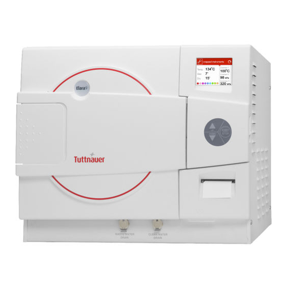
- Page 1 Technician Manual Pre-vacuum Steam Sterilizer with Generator Models ELARA9-D, ELARA11-D Cat. No. MAN205-0498000EN Rev D Tuttnauer Europe B.V., Hoeksteen 11 4815 PR P.O. Box 7191 4800 GD Breda, The Netherlands Tel: 31 (0) 765423510, Fax: 31 (0) 765423540...
-
Page 2: Table Of Contents
TABLE OF CONTENTS General 5 Incoming Inspection 5 Warranty 5 Warranty Statement 6 Safety Instructions 7 General Information 8 Intended Use 8 Introduction 8 Operating Conditions 9 Stickers Description 9 Periodical Tests 10 Specifications 11 Generator Steam Data 15 Autoclave Electrical Data 15 Utilities 16 3.10 Environment Emission Information 16 3.11 Water Quality 16... - Page 3 Description of the programmable component: 24 Software development plan: 26 Control Panel 30 Description and Functions of the Front Panel 30 Displayed Error Messages / Symbols 33 Displayed operational messages / Symbols 33 Screens 35 Screens showing a successfully completed cycle 35 Screens showing aborted cycles after a completed sterilization stage 36 Screens showing a Failure occurrence after a completed sterilization stage 37...
- Page 4 9.21 Drying 84 9.22 Ending 86 9.23 Global (for some models only) 87 9.24 Preliminary Operations for Each Technician Call 89 9.25 Draining the Reservoirs 90 9.26 Safety tests after repair 91 Maintenance and Replacement Procedures 92 10.1 Preliminary Operations for Each Technician Call 92 10.2 Dismantling the Outer Cover of the Autoclave 92 10.3 Emergency Door Opening 93 10.4 Replacing the jacket heating elements 95...
- Page 5 10.27 Replacing the Plastic Handle Cover 116 10.28 Replacing the Printer 117 10.29 Replacing the paper roll 118 10.30 Replacing the Door Switch 119 10.31 Replacing the water pump 121 10.32 Replacing the Plunger or Coil of the Solenoid Valve 122 10.33 Replacing the internal PT100 123 10.34 Replacing the Chamber and Generator Pressure Transducers 124 10.35 Replacing the pressostat 125...
-
Page 6: General
If any damage is found, contact your dealer as soon as possible so that they can file a claim with the shipping carrier and also notify Tuttnauer. All Tuttnauer products are carefully inspected prior to shipment, and all reasonable precautions are taken in preparing them for shipment, to assure safe arrival at their destination. -
Page 7: Warranty Statement
(14) days of purchase or the warranty will be void. Our European Representative’s Technical Service Department can be reached at: Tuttnauer Europe B.V., Hoeksteen 11 4815 PR P.O. Box 7191 4800 GD Breda, The Netherlands ... -
Page 8: Safety Instructions
2 Safety Instructions The autoclave has unique characteristics. Please read and understand this technician manual before first operation of the autoclave. Below are the operating instructions – safety instructions: 1. All autoclave users must receive training in proper usage from an experienced employee. -
Page 9: General Information
3 General Information Intended Use This table-top autoclave is designed for sterilization of medical and surgical goods such as unwrapped and wrapped, solid, hollow, porous products and tubes in ophthalmic, dental and medical clinics, first aid rooms, small laboratories etc. Introduction This autoclave model is an electrically heated sterilizer using steam as a sterilizing agent. -
Page 10: Operating Conditions
Before operating this autoclave read carefully the Operation Manual. After reading this Manual, operating the autoclave will be easy. However since this instrument is built with high technology sensitive components, no attempt should be made by the user or any other unauthorized person to repair or recalibrate it. -
Page 11: Periodical Tests
Periodical Tests PERIOD TEST 1 month Test the safety valve by operating it. Remove the autoclave’s cover, tighten the heaters’ screws and 6 months electrical connections, valves and connectors in the control box. Check the continuity of the grounding connections. Check the temperature and pressure calibration. -
Page 12: Specifications
Specifications Overall Dimensions: ELARA 9-D Page 11... - Page 13 Overall Dimensions: ELARA 11-D Page 12...
- Page 14 Front view Description Description 1 Door switches Ventilation grill 2 Autoclave door On/ off switch / circuit breaker 3 Autoclave cover Keypad 4 Mineral-free water reservoir cover Printer cover 5 Chamber and steam generator safety Autoclave Leg valves 6 Waste water reservoir cover USB connection 7 Display Printer...
- Page 15 Rear View Description Description 1 Mineral-free water reservoir cover 7 Automatic water filling inlet (optional) 2 Waste water reservoir cover 8 RJ45 network connector 3 Ventilation grills 9 Chamber cut-off 4 Air filter service cover 10 Chamber cut-off 5 Opening for calibration 11 Main power electric cable socket 6 Overflow outlet to drain Page 14...
-
Page 16: Generator Steam Data
Property ELARA9-D ELARA11-D Chamber Diameter 230 mm 280 mm Chamber Depth 504 mm 504 mm Chamber volume 19 lit 28 lit. (7.4 gal) Max. Allowable Working Pressure (MAWP) 2.8 bar 2.8 bar Maximum load per item 0.3kg 0.3kg Maximum load per tray 1.5kg... -
Page 17: Utilities
Utilities Property Value See table in 错误!未找到引用源。 Mineral free water Power supply * 1 phase, /230VAC ±10%, 50Hz Recommended circuit breaker * According to the local network. Attention: A switch or circuit-breaker must be included in the building installation. This switch or circuit-breaker shall be in close proximity to the equipment, within easy reach of the operator;... -
Page 18: Directives And Standards
≤0.1 mg/kg Chloride (Cl) ≤0.1 mg/kg Phosphate (P 2 O 5 ) ≤3 μs/cm Conductivity (at 20° C) pH value (degree of acidity) 5 to 7 Appearance Colourless clean without sediment Hardness (Σ Ions of alkaline ≤0.02 mmol/l earth) Compliance with the above data should be tested in accordance with acknowledged analytical methods, by an authorized laboratory. -
Page 19: Installation
4 Installation Caution! The installation and all operations described in this chapter must be done only by an authorized technician. The sterilizer must be placed on a rigid and leveled surface. The stand must be able to withstand the load of the device and loaded material. ELARA9, ELARA11 Counter top able to... -
Page 20: Installation Preparations
Installation preparations 1. Check and verify that the counter carrying the autoclave is a rigid and leveled surface and can carry a load of 225 lb (102kg). Attention: The Elara11 is not designed for use on any standard slide out shelf. If it is necessary to use a slide out shelf, it must be tested and/or rated for 225 Lbs or more. -
Page 21: Operating The Autoclave
Operating the autoclave 1. Plug the power cord into the power socket. 2. Turn on the Main Switch / Circuit Breaker (see front view). 3. Select "Vacuum Test" cycle to keep the steam generator and heating elements from heating up. 4. -
Page 22: Tests
5 TESTS Installation Tests The service technician shall perform the following preliminary checks before operating the autoclave: a. Integrity Check Perform a visual check to verify that there are no dents, scratches, broken parts, etc. Leveling Check Check (visual check) that the surface carrying the autoclave is leveled. c. - Page 23 Check the water reservoir, piping, plastic parts and electric wires. Check and tighten the piping joints to avoid leakage. Check and tighten all screw connections in the control box, heaters and valves and instrumentation. Calibrate the temperature and pressure once a year or in reference to local rules or regulations (refer to the section on Calibration).
-
Page 24: Description Of The Control System
6 Description of the control system Block Diagram Hardware Software Components Main board CPU +memory- Backup power input 24/12 I/O Board 24/12 MCIMX27LVOP4A+MC13783VK5 CPU- STM32F103R6T6 Input R.T.C (including Battery) Input -24 Digital Outputs M41T81SM6E -2 Analog outputs COM1 Memory card expansion (RS232) -9 Digital inputs MAX323... -
Page 25: Description Of The Programmable Component
Description of the programmable component: User Interface Keypad: The keypad has three push buttons: Down key Up key Start/stop key Display: The control system has 3.2 " color graphical display. USB socket: socket is intended to load cycles' history from flash a memory (disk key). - Page 26 Digital outputs Digital Outputs Description Unlock Door SSR that operates the chamber Chamber heat J13/6 heaters Water pump Option , relay that operates the J13/10 valve water pump valve slow exhaust slow exhaust valve J14/6 Fast exhaust Fast exhaust valve J14/8 Actuators The control system operates electrical valves (solenoids), pumps, etc…...
-
Page 27: Software Development Plan
Software development plan: The hardware is consisted of cards: MAIN and IO Main card Ethernet Keypad Connector Battery Power Supply Connector Not in use Connector to IO Board Analog inputs Connector Inputs (24V DC) inpu inpu Pres inpu Pres sure sure inpu Pres... - Page 28 Development tools (MAIN card) The software develop environment is on Microsoft Visual Studio 2005 that includes the Microsoft Platform Builder for Windows CE 6.0. The specific Tuttnauer system application is written in C Sharp.net on Microsoft Compact Framework .net IO Card...
- Page 29 At the end of the check process of the digital and analog ports, the communication channel is checked, in case of receiving a request, the request is checked and if the request is legitimate it will be taken care of. The IO card is controlled by the MAIN card.
- Page 30 1.6 06 - Write (only at the first time) to IO his ID and software number. 2. First Byte (Byte 1). The first byte identifies ID functionality request. It can be one of the numbers in a paragraph. 3. The second byte will present the data size if the main board asks to write information to the IO.
-
Page 31: Control Panel
7 Control Panel Description Display Main switch and circuit breaker Keypad USB Port Printer (optional) Description and Functions of the Front Panel The front panel is composed of 3 sections (see picture on previous page): Page 30... - Page 32 3. Visual Information Center 4. Control Center. 5. Data Output Center Visual Information Center The information center contains the display which is an LCD panel used to display the current status of the autoclave and any Operational Messages or Error Messages. Program description: ...
- Page 33 The network port (located on the rear of the unit) can be used to connect to a local network and download information to Tuttnauer’s R.PC.R software. The RPCR software has been developed especially for the Tuttnauer autoclaves and is an excellent report generating tool.
-
Page 34: Displayed Error Messages / Symbols
Track the parameter settings that have been used in each of the cycles and stages run. Choose the style of the report to view; either graph, table, or a print All reports can be saved as a PDF. ... - Page 35 Enter the customer menu This symbol is displayed as described in this when Cycle by Clock manual to change the mode is performed. time or to cancel this option. This message is Enter the customer menu displayed if the user as described in this "Cycle by clock is presses START/STOP...
-
Page 36: Screens
8 Screens During the cycle the screen will change to let you know how the cycle is progressing. The following screens are a representation of what will be seen in all cycles. Screens showing a successfully completed cycle 1. System Ready 2. -
Page 37: Screens Showing Aborted Cycles After A Completed Sterilization Stage
Screens showing aborted cycles after a completed sterilization stage The sterilization phase ended successfully – the cycle was aborted and the reason for the failure is displayed. When the sterilization portion of the cycle is successful the display remains white even though the cycle was aborted. The next three scenarios show examples of possible error messages: Canceled by user after complete sterilization stage The sterilization stage ended successfully, however the operator manually... -
Page 38: Screens Showing A Failure Occurrence After A Completed Sterilization Stage
Screens showing a Failure occurrence after a completed sterilization stage The sterilization stage ended successfully, however the chamber indicated that there was high pressure during the exhaust phase which resulted in the following sequence of screens with the last screen showing the reason for the aborted cycle. - Page 39 Failure due to Cancellation by user before completing the sterilization stage Door is open during the cycle before completing the sterilization stage In this case the door switch indicated that the door was opened which resulted in the following screen showing the reason for the aborted cycle When "Cycle Failed"...
-
Page 40: Checking And Changing Parameters And Other Data
9 Checking and Changing Parameters And Other Data Bacsoft control panel allows changing parameters of the cycle and of the system, exporting various data to, and importing from, a USB device or to the printer, and some other options. Cycle parameters are changeable for Custom programs only (see Duplicate cycles), with the exception of the Temperature sensors, Displayed inputs, and Dry Time. -
Page 41: Changing A Parameter
Note: To exit every screen and to return to the previous screen (to get one level up): move the cursor to Exit by pressing the UP or DOWN keys and then press the Start/Stop key. - or- press the UP and DOWN keys simultaneously. In the next chapter you will see how to change the required parameter as desired. - Page 42 Below is the typical parameter changing screen: Note: Please note the maximum and minimum values for this parameter shown on the screen. Your value must be within these boundaries. Below is the example of changing the Dry time parameter on the screen used in the previous section: Page 41...
-
Page 43: Quick Options Screen
Note: To exit every screen and to return to the previous screen: move the cursor to Exit by pressing the UP or DOWN keys and then press the Start/Stop key - or- press the UP and DOWN keys simultaneously Quick options screen When the autoclave is on and no cycle is running, press Up and Down keys simultaneously to enter the Quick options screen. - Page 44 Below you can find instructions how to login and enter the Main menu. Section 7.1 above explains how to browse through the menus; section 7.2 explains how to change a parameter. Below is the explanation of the Quick Options. Export to USB This subdirectory allows you to export settings and cycles history to the USB device.
- Page 45 Choose Export all settings to USB device. Press the Start/Stop key. The following screen will appear: To export cycles history: Choose All cycles history, 10 Cycles, or 50 Cycles. Press the Start/Stop key. The following screen will appear: 3. Remove the USB device from the USB Socket. Print cycles This subdirectory allows printing out cycle reports for a number of previous cycles (See the Printer handling section of the Operation and maintenance...
- Page 46 1. Enter the Print Cycles screen. 1. Choose Print last cycle, Print last 5 cycles, or Print last 10 cycles. 2. Press the Start/Stop key. The cycle reports will be printed. Version Information This directory allows viewing information of the current, factory default, and previous software versions.
- Page 47 Start cycle by clock This subdirectory enables the operator to start the cycle at the time set by this paramter. 1. Enter the Start cycle by clock screen. The following screen will appear: On the Start cycle by clock screen, the time is displayed in the form “HH:MM”. The hour range is 24 hours (i.e.
- Page 48 1. Exit the Enabling the Start Cycle by Clock. The start cycle by clock icon appears on the display: Disabling the START CYCLE BY CLOCK 2. On the Start Cycle by Clock screen, move the cursor to Disabled. Press Up or Down key to disable Starting cycle by clock.
-
Page 49: Logging In And Entering The Main Menu
On the Set date and time screen, the time is displayed in the upper row in the form "HH:MM:SS". The hour range is 24 hour (i.e. from "0" to "24"). The date is displayed in the lower row in the form "DD: MMM: YYYY". 1. - Page 50 When the autoclave is on and no cycle is running, press the up and down keys simultaneously to enter the Quick Options screen (see 9.3). On this screen you can either proceed to login (see below) or choose one of the quick options available without login.
-
Page 51: Directories And Subdirectories
Set the code to 0321. You will get to the Main menu. Below is the list and the explanation of the options available on the Main Menu. Directories and subdirectories Bacsoft control panel provides an interface that consists of control screens available through an easy scrollable menu tree. - Page 52 Keep Heat Heating Sterilization Cooling (“C” models only) Exhaust Drying Ending Global Print Rate All Print Rate Sterilization Screen Saver Pressure calibration high System Parameters Pressure calibration low Temperature calibration high Temperature calibration low Cycle Print Gap View digital inputs state View digital outputs state Inputs/Outputs Test digital outputs...
- Page 53 Test RTC Printer test Print all gain and offset Enable cycles Set Language Set temperature units Advanced Options Set pressure units Duplicate cycles Deletaqaqe custom cycles Set external IP address Import application from USB Import all settings from USB device Version Handling Import application and setting from USB Return to factory default settings...
-
Page 54: System Parameters
System Parameters This menu is listing the system parameters that are the same for all cycles. Browse to the following folder: Main menu\System parameters You will see the following screen: Below is the instruction for changing the system parameters. Print Rate All In this menu you can define the time interval for printing out the cycle status, for all the stages except sterilization: The default is 3 minutes. - Page 55 Change the parameter as desired Screen Saver In this menu you can define the screensaver delay time, i. e. how long the keyboard will be untouched before the screensaver activates. Browse to the following folder: System parameters\Screen Saver Change the parameter as desired. Pressure calibration high In this menu you can define the high calibration point for pressure.
-
Page 56: Inputs/Outputs
Browse to the following folder: System parameters\Temperature calibration low Change the parameter as desired Cycle Print Gap This parameter defines the time interval between printing the current values of the cycle (See the printer output section). Browse to the following folder: System parameters\Cycle Print Gap Change the parameter as desired Inputs/Outputs... - Page 57 Browse to the following folder: Inputs/Outputs\View digital inputs state View digital outputs state In this menu you can view, at any stage, which digital outputs are being controlled at the moment. Browse) to the following folder: Inputs/Outputs\View digital outputs state Test digital outputs In this menu you can view the normal function of all the autoclave elements: valves, heating elements, pumps, etc.
- Page 58 2. Press Up or down key to choose the input to calibrate and press Start/Stop. The following screen will appear: See below description of each option. Auto calibrate Bacsoft software has an option for automatic calibration using the PT100 simulator. On the calibration options screen, choose Auto calibrate.
- Page 59 Calibrate analog input This menu allows calibrating analog inputs manually. 1. On the calibration options screen, choose Calibrate analog input. The following screen will appear: 2. In the Actual field, change the high and low values of the input as desired . Set gain and offset 1.
- Page 60 Change gain and offset as desired . Restore last calibration There is an option to restore the gain and offset values set at previous calibration. 1. On the calibration options screen, choose Restore last calibration. The following screen will appear: 2.
- Page 61 Restore default calibration There is an option to restore the default (factory) gain and offset values 1. On the calibration options screen, choose Restore last calibration. The following screen will appear: 2. Using the up and down keys, move your cursor to confirm and press Start/Stop.
-
Page 62: Maintenance
Maintenance Maintenance procedures provided by Bacsoft software allow you additional tests and USB input/output options. Browse to the following folder: Main menu\Maintenance You will see the following screen listing the maintenance options: Below is the instruction for autoclave’s maintenance menu. Export gain offset to USB In this menu you can export to USB the gain and offset you have got as a result of calibration. - Page 63 Maintenance\ Export gain offset to USB Import gain and offset from USB In this menu you can import from the USB the gain and offset documents you have got as a result of calibration to the autoclave. Browse to the following folder: Maintenance\Import gain and offset from USB Press Start/Stop.
- Page 64 2. Leave the door open for 2 minutes at least. Ambient temperature should be less than 45° C. Note: Please reset the atmospheric pressure when you install the autoclave for the first time, and each time you relocate or calibrate the autoclave. Test RTC In this menu you can check the two clocks.
- Page 65 3. Using the Up and Down keys, move the cursor to Exit. Printer test In this menu you can check the normal function of the printer. The printer will print the list of errors. Browse to the following folder: Maintenance\Printer test The following screen will appear to confirm that the test has been done.
-
Page 66: Advanced Options
Print all gain and offset In this menu you can print all the gain and offset for all the pressures and temperatures in the autoclave (Chamber Temperature, Chamber Pressure, Chamber Water Level, Mineral Free Water Level. Browse to the following folder: Maintenance\Print all gain and offset See below the example of a printout: Chamber Temperature... - Page 67 Below is the instruction for the Advanced options menu. Enable cycles In this menu you can enable only the cycles you want to use. The cycles you do not want to use will not appear on the screen. Browse to the following folder: Advanced Options\Enable cycles Move cursor to the cycles you want to enable/disable and check/unchek them as desired.
- Page 68 Advanced Options\Set Language Note: There are more languages than you see on the screen above. Just scroll down to see more. 2. Move the cursor to the desired language and check it. The following screen will appear: The machine will be restarted and the main screen (current cycle) will appear in the chosen language.
- Page 69 Set pressure units In this menu you can you can set the pressure units (kPa, Psia, Psig, BarA, BarG) for screens and printouts. Browse to the following folder: Advanced Options\Set pressure units Change the parameter as desired Duplicate cycles In this menu you can create a copy of one of the cycles with all its parameters (the parameters can be changed then).
- Page 70 2. Give the name to your cycle. 3. Exit the menus until you get to the main screen. 4. Select your newly created program. Note: you can select the program only when the autoclave door is open. 5. Login again as Technician (see 9.4). 6.
- Page 71 The following screen will appear: Now you can alter the cycle parameters as desired. Delete custom cycles In this menu you can delete the custom cycles that were created. Browse to the following folder: Advanced Options\Delete custom cycles 1. Move the cursor to the cycle you wish to delete. Press Start/Stop key to select/deselect the cycles.
-
Page 72: Version Handling
The selected custom cycle is now deleted. Set external IP address This option allows to set specific external IP address to be used for remote RCPR connection. Browse to the following folder: Advanced Options\Set external IP address Set the External IP Address as desired . Version handling 9.10 The version handling menu provides tools to import, export, and restore the... - Page 73 Below is the instruction for version handling. Import application from USB In this menu you can replace the autoclave software with the application software from the USB device to the autoclave. 1. Browse to the following folder: Version handling\Import application from USB The system will prompt you to confirm import 2.
- Page 74 On this screen, you will see the model name and parameters checksum of the settings saved on the USB device. 2. Move the cursor to Confirm and press Start/Stop. The following screen will appear: 3. There is an option to keep the old serial number or calibration data while exporting all the rest from USB.
-
Page 75: Cycle Parameters
Version handling\Import application and setting from USB 5. Move the cursor to Confirm and press Start/Stop. Return to factory default settings In this menu you can restore the default values of all the changeable parameters of the cycle and the system. Default settings are those your autoclave had when it left the factory. - Page 76 Note: For all the standard sterilization cycles, and for Bowie and Dick test, the only changeable cycle parameter is dry time (you will not see other parameters on your screen). For the custom cycles created by duplication, and for the Warm Up cycle, all the options listed in table below are changeable.
- Page 77 Temperature 1 stay Temperature 1 stay time Keep Heat Temperature 2 stay Temperature 2 stay time Sterilization Temperature Heating Sterilization Temperature Sterilization Sterilization Time Cool Mode Cooling (“C” models Cool End Temperature only) Cool Exhaust Rate Exhaust Exhaust Mode Dry Time Dry Heat On 1 Dry Heat Off 1 Drying...
-
Page 78: Temperature Sensors
Jacket Temperature The following chapters explain meaning and usage of the control screens for the cycle parameters. Temperature sensors 9.12 Temperature sensors \Chamber Temperature In case a machine has a number of temperature sensors, there is an option to assign every chamber temperature sensor to be one of the following: main, reference, not in use. -
Page 79: Purge (Generator Models Only)
1. Browse to the following folder: Cycle parameters\Displayed inputs\First The following screen will appear: Using the Up and Down keys, choose first, second, or third. 2. The following screen will appear: 3. Using Up and Down keys, move the cursor to the desired radio button and choose it by pressing Start/Stop. -
Page 80: Create Pulse
2. Change the parameters as desired. Create Pulse 9.15 This menu allows to set parameters for each pulse of the program (see below). Pulse A Count This parameter defines how many times the pulse of each type (A, B) is repeated. -
Page 81: Keep Heat
Note: Pulse A and B counts for standard programs equal one, with the exception of Hollow load, Waste, and Bowie and Dick test (pre-vacuum models only), whose pulse count equals four. Pulse A Stay Time This parameter defines the value of delay after the required pressure for the pulse is reached. - Page 82 (Temperature 1 or 2 stay time). Keep Heat starts before heating and is used to melt solid loads of substances such as agar. Keep Heat is needed for such loads to become completely liquid before sterilization starts. Below is the example of changing the Temperature 1 stay/stay time. Temperature 1 stay This parameter allows you to set two temperatures at which the process will be paused (Keep Heat).
-
Page 83: Heating
1. Browse to the following folder: Cycle parameters\Keep Heat\Temperature 1 stay time Note: same parameters are available for temperature 2. 2. Change the parameter as desired . Heating 9.17 Sterilization Temperature This parameter defines the heating temperature for the cycle. At reaching this temperature, sterilization stage starts. -
Page 84: Cooling ("C" Models Only)
Sterilization Time This parameter defines duration of the sterilization stage for the cycle. 3. Browse to the following folder: Cycle parameters\ Sterilization\Sterilization Time 4. Change the parameter as desired . Cooling (“C” models only) 9.19 This menu defines parameters for the cooling stage. Cool Mode If the setup of your model has the cooling option, and the cycle has the cooling stage, the Cool mode parameter equals 1, otherwise it equals 0. -
Page 85: Exhaust
2. Change the parameter as desired . Cool Exhaust Rate This parameter defines how quickly the pressure will go down during exhaust after cooling. 1. Browse to the following folder: Cycle parameters\Cool Mode\Cool Exhaust Rate 2. Change the parameter as desired . Exhaust 9.20 This menu defines parameters for the exhaust stage. - Page 86 Dry Time This parameter defines duration of the drying stage for the cycle. 1. Browse to the following folder: Cycle parameters\Drying\Dry Time 2. Change the parameter as desired . Drying stage is divided into two stages. For each stage you can set the total time, on time and off time.
-
Page 87: Ending
This parameter defines how long will the heating elements be off for the Dry First Stage. 1. Browse to the following folder: Cycle parameters\Drying\Dry Heat Off 1 2. Change the parameter as desired . Note: There are Dry heat On 2 and Dry heat Off 2 parameters for the Dry Second Stage of the drying. -
Page 88: Global (For Some Models Only)
1. Browse to the following folder: Cycle parameters\Ending\End Temperature 2. Change the parameter as desired Global (for some models only) 9.23 This menu defines the global cycle parameters. F0 mode This parameter checks how long has the load been in sterilization conditions (pressure, temperature) before the sterilization stage actually begins. - Page 89 2. Change the parameter as desired). Multiple Cycles This parameter allows you to repeat, for testing purposes, the same cycle several times without reloading the autoclave. The number or repetitions is defined by this parameter. 1. Browse to the following folder: Cycle parameters\Global\Multiple Cycles 2.
-
Page 90: Preliminary Operations For Each Technician Call
Preliminary Operations for Each Technician Call 9.24 1. In order to maintain efficient service, the technician must perform the following: Cleaning the following, if requires cleaning: Chamber, trays and trays holder. Filters. Bottom parts and plungers of the solenoid valves. ... -
Page 91: Draining The Reservoirs
Draining the Reservoirs 9.25 (Applies to the clean-water reservoir and to the waste-water reservoir) To drain the reservoir, use item (5) with the plastic hose (6) attached to it (supplied with the autoclave). Insert part (5) into valve (3) and press it until you hear a “click”. -
Page 92: Safety Tests After Repair
Safety tests after repair 9.26 ATTENTION! After every repair or dismantling the enclosure, the autoclave should pass two safety electrical test by the Service Engineer. The following shall be performed: 1. Enclosure Leakage Current Test. Every autoclave should pass this test as follows: 1. -
Page 93: Maintenance And Replacement Procedures
10 Maintenance and Replacement Procedures Preliminary Operations for Each Technician Call 10.1 In order to maintain efficient service, the technician must perform the following: 1. Inspect and clean if needed, the following: Chamber, trays and trays holder (see Maintenance Instructions in the Operator’s Manual). -
Page 94: Emergency Door Opening
5. Remove the grounding wires from the outer cover. Emergency Door Opening 10.3 Caution! Before starting, disconnect the instrument from the power source and ensure that there is no pressure in the autoclave. Decreasing the pressure Since the autoclave is not equipped with an analogue pressure gauge, and the display is off (no electrical power), it is recommended to wait approximately one hour to verify that the pressure and temperature have decreased to ambient conditions. - Page 95 2. Pull the ring (4) of the safety valve using a tool, i.e. screwdriver, hook etc. (3). Pull the safety valve ring until steam ceases to escape from the safety valve. Be careful not to burn your hands. Description water reservoir cover Safety valve Pulling device Pressure relief ring...
-
Page 96: Replacing The Jacket Heating Elements
Opening the door Caution! This option is for emergency cases only! Before opening the door, always make sure that there is no pressure in the chamber. 1. Insert a 2 mm (0.08") pin (1) into the hole (2) located above the door opening handle (3). -
Page 97: Replacing The Pt100 Temperature Sensor And Cut -Off Thermostat Of The Jacket Heater
Replacing the PT100 Temperature Sensor and cut –off 10.5 thermostat of the jacket heater The autoclave is equipped with a temperature thermostat, which protects the heaters and the autoclave against overheating, during the dry cycle. This device reconnects automatically when the chamber cools down. Caution! Before starting, disconnect the instrument from the power source and ensure that there is no pressure in the autoclave. -
Page 98: Replacing The Water Reservoir Water Electrodes
Replacing the Water Reservoir Water Electrodes 10.6 1. Open the outer covers of the autoclave (see 10.2). 2. Disconnect the wires of the electrode (1). 3. Unscrew the nut (2) 4. Apply some leakage prevention glue inside the nut and tighten it 5. - Page 99 2. Disconnect the drainpipe from the valve, using a 9/16” wrench. 3. Remove the nut (3) and the ring for drain valve (2). 4. Remove the drain valve (1) from the panel. 5. Install a new valve according to the drawing below. CMT240-0020 CMT240-0003 VLV170-0066...
-
Page 100: Replacing The Water Filling Pipe
6. Verify that there is no leakage. Replacing the water filling pipe. 10.8 1. Open the autoclave cover (see 11.2). 2. To replace the water pipe (1): 2.1 Unscrew the two nuts connecting the pipe to the water tank (2). 2.2 Press the three pins in the inner side of the front panel that release the pipe and the water filling tank (3, 4). -
Page 101: Replacing The Door Safety Microswitch
2. While holding the door handle (2) with your thumbs, gently press the cover (3) outwards to click it open. (4) Replacing the door safety microswitch 10.10 1. Unscrew the 2 screws (1). 2. Release the microswitch together with its metal cover (2) so to release the red wires. -
Page 102: Replacing The Main Switch
Replacing the main switch 10.11 Caution! Before starting, disconnect the instrument from the power source and ensure that there is no pressure in the chamber. Allow the autoclave to cool before removing outer covers. 1. Remove the control electronic boards (see 10.24). 2. -
Page 103: Replacing The Air Filter
Replacing the Air Filter 10.12 Caution! Before proceeding, make sure that the electric cord is disconnected and there is no pressure in the autoclave. 1. Pull out the filter cover/seat (1) 2. Pull out the air filter from its cover/seat. 3. - Page 104 3. Unscrew the 4 screws (3). 4. Remove the old circuit breaker and replace it with a new one. Use only an original circuit breaker supplied by Tuttnauer. 5. Assemble the new circuit breaker with the 4 screws (3). 6. Connect the electrical connections (3).
-
Page 105: Replacing The Door Safety Microwitch ("Door Switch")
Replacing the Door Safety Microwitch (“Door switch”) 10.14 Caution! Before starting, disconnect the instrument from the power source and verify that there is no pressure in the chamber or the generator. Allow the autoclave to cool before removing outer covers. 1. -
Page 106: Replacing The Solid State Relay (Ssr)
Caution! Make sure that the door switch is installed correctly! Check that the operational message “Door is Open" is displayed when the door is opened and that the message disappears when the door is closed. Replacing the Solid State Relay (SSR) 10.15 1. -
Page 107: Replacing The Transformer
Replacing the Transformer. 10.16 1. Unscrew the nuts (1) of the transformer axis. 2. Disconnect the wires and fuses (see 错误!未找到引用源。, Replacing the Fuse of the Transformer below). 3. Replace the transformer, reconnect the wires, close the compartment. Replacing the fuse of the transformer 10.17 Caution! Before starting, disconnect the instrument from the power source. -
Page 108: Replacing The Safety Valve
Replacing the Safety Valve 10.18 Caution! Before starting, disconnect the instrument from the power source and ensure that there is no pressure in the autoclave. Allow the autoclave to cool before removing outer covers. The safety valve is installed to protect the system from over pressurizing should all the electrical controls fail. -
Page 109: Replacing The Steam Generator Heating Elements
9. Press the STOP key to stop operation, and exhaust steam from chamber. 10. Wait until pressure decreases to zero, only then can the door be opened. Description Safety valve base Safety valve Pressure relief nut ASME Description Safety valve base Safety valve Pressure relief nut Replacing the steam generator heating elements... -
Page 110: Replacing The Steam Generator Cut-Off Thermostat
1. Open the outer covers of the autoclave. 2. Empty the generator. 3. Pull the thermostat out of its sleeve (1). 4. Disconnect the wires of the heating elements from the porcelain connector. 5. Unscrew the bug nut (2) bearing the heating elements to the generator. 6. -
Page 111: Replacing And Cleaning The Generator's Water Level Electrode
Replacing and cleaning the generator’s water level 10.21 electrode Caution! Before starting, disconnect the instrument from the power source and ensure that there is no pressure in the autoclave. Allow the autoclave to cool before removing outer covers. 1. Open the outer covers of the autoclave. 2. -
Page 112: Replacing The Drain Valve
Replacing the Drain Valve 10.22 There are two drain valves on the front of the autoclave. One drains the mineral free water from the clean reservoir and the other drains the water from the waste water reservoir. Caution! Before starting, disconnect the instrument from the power source and ensure that there is no pressure in the autoclave. - Page 113 2. Line the inside of both sides/walls of the gasket groove with grease (red arrows). Note: It is recommended to use a silicone based lubricant such as Würth Silicone Emulsia (Tuttnauer part number SEA 095-0117). If you had purchased a replacement door gasket it will have come with a small packet of lubricant.
-
Page 114: Replacing The Front Panel
Caution! Make sure to put the gasket evenly without waves, humps, or cavities. See drawing the right direction of the gasket. Replacing the Front Panel 10.24 Caution! Before starting, disconnect the instrument from the power source and ensure that there is no pressure in the autoclave. Allow the autoclave to cool before replacing the Panel. -
Page 115: Replacing The Printer Door
4. Remove the digital card located on the rear side of the panel). 5. Remove the printer (see 10.28 ). 6. Assemble the digital card on the new panel. 7. Assemble the printer on the new panel. 8. Assemble the panel and fasten it to the autoclave with the 4 fastening screws (1 &... -
Page 116: Replacing The Door Handle
Replacing the Door Handle 10.26 Caution! Before starting, ensure that there is no pressure in the autoclave. Allow the autoclave to cool before replacing the Door Handle. Do not disconnect the electric power, since disconnecting the power will lock the handle and prevent replacement of the handle. 1. -
Page 117: Replacing The Plastic Handle Cover
Replacing the Plastic Handle Cover 10.27 Caution! Before starting, ensure that there is no pressure in the autoclave. Allow the autoclave to cool before replacing the Door Handle Cover. Do not disconnect the electric power, since disconnecting the power will lock the handle and prevent replacement of the handle cover. -
Page 118: Replacing The Printer
Replacing the Printer 10.28 Caution! Before starting, disconnect the instrument from the power source and ensure that there is no pressure in the autoclave. Allow the autoclave to cool before removing outer covers. 1. Remove the panel (see 10.24) to reveal the internal part and the electrical connectors. -
Page 119: Replacing The Paper Roll
Replacing the paper roll 10.29 When the printer’s green LED flashes, it means that the printer is out of paper, or the paper is mishandled. In the first case, proceed as follows: 1. Press the printer button (1) to open the paper compartment (2). 2. -
Page 120: Replacing The Door Switch
Replacing the Door Switch 10.30 Caution! Before starting, disconnect the instrument from the power source and verify that there is no pressure in the chamber or the generator. Allow the autoclave to cool before removing outer covers. 1. Remove the autoclave top and left covers (see 10.2 ). 2. - Page 121 5. Remove the door switch from the autoclave. 6. Release nut (6) and unscrew the door switch (4) from the door switch adapter (5). 7. Assemble the new door switch to the adapter. Verify that the wheel protrudes (A) approx. 0.37"-0.38" (9.5-10mm) from the adapter (5) and tighten nut (6).
-
Page 122: Replacing The Water Pump
9.3. If these two conditions are fulfilled, dimension "A" is correct, tighten screws (1). 9.4. If dimension "A" is not correct, remove the microswitch from the panel, turn the adapter 1/2 a turn clockwise or counterclockwise as required and reassemble it to the panel. 9.5. -
Page 123: Replacing The Plunger Or Coil Of The Solenoid Valve
6. Replace the damaged pump with a new pump. 7. Reconnect wiring and piping. 8. Reassemble the outer cover. 9. Turn on the autoclave and verify it operates correctly. Description Cat. No. Rubber shock absorber SKR203-0006 Fitting 5/16”x1/8” (straight) Screw BOL191-0140 NUT192-0191... -
Page 124: Replacing The Internal Pt100
5. Reassemble the coil (2) and the nut (1). 6. Re-install the autoclave cover. Replacing the internal PT100 10.33 Caution! Before starting, disconnect the instrument from the power source and ensure that there is no pressure in the autoclave. Allow the autoclave to cool before removing outer covers. 1. -
Page 125: Replacing The Chamber And Generator Pressure Transducers
Replacing the Chamber and Generator Pressure 10.34 Transducers Caution! Before proceeding, make sure that the electric cord is disconnected and there is no pressure in the autoclave. Generator Chamber 1. Remove the outer cover of the autoclave. 2. Unscrew the screw (1). 3. -
Page 126: Replacing The Pressostat
8. Install a new transducer. 9. Assemble the cap to the new transducer and tighten it with screw (1). 10. Reassemble the outer cover. Replacing the pressostat 10.35 Caution! Before starting, disconnect the instrument from the power source and ensure that there is no pressure in the autoclave. Allow the autoclave to cool before removing outer covers. -
Page 127: Replacing The Door Locking Solenoid
Replacing the door locking solenoid 10.36 Caution! 1. Open the door. 2. Remove the door cover (3). 3. Release the locking mechanism spring (5) from the front spring holder (6) or brace the locking mechanism so it will not move while you are working on it. - Page 128 6. Using the correct size screwdriver (9) insert it from the top and unscrew the door solenoid mounting cylinder (11) from the door locking mechanism brass holder (10). Upper door bridge Door handle 7. Disassemble the solenoid (15) from the mounting cylinder (11). 8.
-
Page 129: 11 Troubleshooting
11 Troubleshooting This troubleshooting chart enables the technician to repair the autoclave Only technical personnel having proper qualifications and holding technical documentation (including a technician manual) and adequate information are authorized to service the apparatus. It is recommended to use the technician function: view digital output; view analog outputs;... - Page 130 Possible causes Check- Symptoms Corrective Action ups and tests and printer. Faulty power supply. The door gasket is Clean the door gasket. dirty. (see Daily Maintenance in leaking at the (see Daily Maintenance in Operator's manual). door Operator's manual) Replace the door gasket.
- Page 131 Possible causes Check- Symptoms Corrective Action ups and tests If the problem persists, perform the following with SSR, Analog During the 'Ending' stage board, and temp/pressure the chamber temperature sensors: does not go below the temperature defined in Test parameter 'End If this doesn’t help, Temperature' for X minutes recalibrate.
- Page 132 Possible causes Check- Symptoms Corrective Action ups and tests During 'Sterilization' stage, If the problem persists, perform the chamber temperature the following with SSR, Analog goes above the value board, and temp/pressure defined in parameter sensors: 'Sterilization Temperature' + value of parameter Test If this doesn’t help, 'Sterilization temperature...
- Page 133 Possible causes Check- Symptoms Corrective Action ups and tests Heating elements go on working beyond the required time. Faulty SSR or Analog board. Faulty calibration of temperature or pressure sensors. Faulty temperature or pressure sensors. During 'Sterilization' stage, Perform a new cycle. the chamber pressure goes below the value of 'Sterilization Pressure'.
- Page 134 Possible causes Check- Symptoms Corrective Action ups and tests Faulty calibration of temperature and pressure sensors. Faulty temperature or pressure sensors. Chamber pressure has not If the problem persists, replace reached the requested high the door gasket. pressure after the time defined by cycle parameter 'Pressure Time Error' Possible causes:...
- Page 135 Possible causes Check- Symptoms Corrective Action ups and tests Faulty thermostat Faulty cut-off If it happened before or during the sterilization stage, repeat the Power down has occurred cycle. If power down happened Power down during the cycle. after the sterilization stage, repeating the cycle is not necessary, it’s up to the operator.
-
Page 136: 12 List Of Spare Parts
12 List of Spare Parts ELARA11--U-D Part Number Desription Pan Head Machine Screw, Phillips, M4x8, St. St. A2, BOL191-0158 DIN7985 CMT098-0002 Nipple, Water level electrode GAS080-0260 Gasket for Flate Door-11",Silicone Hex Socket Flat Cap Screw, 1/4UNCx5/8, St. St. A2,Fully BOL191-0136 Threaded LOK254-0001 Washer, locking solenoid pin, 1730, 2340, 2540... - Page 137 Part Number Desription CTP201-0159 Fan, 230VAC, 150x172x38 FIL175-0069 Fan guard, 170 mm, NiCr plated, FGW-162A-5, Cooltron ARM172-0026 Check Valve, Spring Disk, 1/4"BSP, St.St., MONDEO Pan Head Machine Screw, Phillips, M4x8, St. St. A2, BOL191-0158 DIN7985 PNE195-0040 Silencer 1/4" SOL026-0039 Valve, Solenoid, 2/2 way, 1/4"BSPx4.5, NC, 24VAC, 8W ARM172-0026 Check Valve, Spring Disk, 1/4"BSP, St.St., MONDEO CMT100-0004...
- Page 138 Part Number Desription CMT196-0001 Bushing, water level electrode Electrode, Water Level, Assembly, For Electronic TTA CMT196-0004 Length: 58mm GAS086-0001 Tube, Teflon, Water Level Electrode CMV196-0002 Electrode, Water Level, 58mm, TTA Terminal, male, brass, w/o isolation, PC1L18704LR, K.S. ELE039-0048 Terminals NUT192-0191 Hex Nut, M4X3.2, Stainless Steel A2, DIN934 Serrated Lock Washers External Teeth, M6, Steel,Zinc NUT193-0292...
- Page 139 Part Number Desription pole CTP201-0318 Fan, 24VDC, Dia. 80mmx20mm, 34.6CFM Female Connector, 6 Pole,5mm Pin Spacing with Coding ELE039-1055 Fingers Closed Female Connector,8 Pole,5mm Pin Spacing with Coding ELE039-1056 Fingers Closed ELE035-0009 Fuse, 5x20mm, Glass tube, 250V, 2A,F ELE035-0144 Power Supply, 24VDC, 1A ELE035-0144 Power Supply, 24VDC, 1A NUT192-0217...
- Page 140 Part Number Desription Pan Head Machine Screw, Phillips, M4x8, St. St. A2, BOL191-0158 DIN7985 Pan Head Tapping Screw, Philips, 4.8x13, Flat Point, BOL194-0340 DIN7981 FH Pan Head Tapping Screw, Philips, 4.8x19, Flat Point, BOL194-0341 DIN7981 FH CMT240-0097 Handle, Tray, TTA 1730, 2340, 2540 CMT240-0002 Handel for Tray COV411-0011...
- Page 141 Part Number Desription LOK411-0044 Safety Switch Holder for Elara door LOK692-0039 Pin, Cotter, 2.0x16 mm NUT193-0275 Plain Washer, 1X5.3X13, Stainless Steel A2 NUT193-0283 Plain Washer, 1.2X7.45X16.1, Stainless Steel A2 Spring Lock Washers With Square Ends, 1/4, St. St. A2, NUT193-0317 DIN127B THE039-0036 Connector, Ceramic, No.3, Double...
- Page 142 Part Number Desription Terminals FIT100-0216 Sleeve, Tube 1/4, Brass, 60C-4, Parker FIT100-0226 Nut for Sleeve, Tube 1/4, Thread 7/16-24, Brass FIT100-0806 Male Adapter, Elbow, 90° , 1/8"BSP For 6mm Hose GAS080-0022 O-Ring, ID 2.84, W=2.62, 2-104 EPDM NUT193-0340 Teflon Ring for water tank PIP411-0002 Coil, Cooling, ELARA RES411-0005...
- Page 143 Part Number Desription VLV170-0014 Cock, Drain VLV170-0015 Nut, Cock, Drain FIL175-0042 Filter, Air, 0.2 Micron, Model 50mm D FIL175-0066 Filter, 0.2 micron, 92WM, Cobetter FIL175-0087 Filter, Water, PVC Assy. FIT100-0216 Sleeve, Tube 1/4, Brass, 60C-4, Parker FIT100-0226 Nut for Sleeve, Tube 1/4, Thread 7/16-24, Brass GAS083-0002 Tube, Silicone, Clear, Translucent, 5x10mm, 58 Shore A GAS083-0004...
- Page 144 Part Number Desription POL067-0048 Window, Clear for Control Sys. Screen - Bacsoft THE002-0052 Panel printer, Thermal, 24 Columns Thermal paper for CUSTOM PLUSII printer roll 57mm THE002-0066 d=50mm THE002-0061 Full Color graphical display 3.5" WIR040-0170 Cable kit for PLUSII-S-0004 Printer Sensor, Temperature, 5x100, 54400, Sontec, Assy.
- Page 145 Part Number Desription WIR040-0003 ELECTRIC CABLE PLUG+SOCKET 10A, 250V, EUR " E LARA11-230-W-W-D" Part Number Desription Pan Head Machine Screw, Phillips, M4x8, St. St. A2, BOL191-0158 DIN7985 CMT098-0002 Nipple, Water level electrode GAS080-0260 Gasket for Flate Door-11",Silicone Hex Socket Flat Cap Screw, 1/4UNCx5/8, St. St. A2,Fully BOL191-0136 Threaded LOK254-0001...
- Page 146 Part Number Desription FIL175-0069 Fan guard, 170 mm, NiCr plated, FGW-162A-5, Cooltron BOL191-0142 Pan Head Machine Screw, Phillips, 1/4UNCx3/4, St.St. A2 NUT192-0155 Flange Hex Nut, 1/4UNC,Grade 2, Steel, Zinc Plated PUM055-0021 Water Pump, 230V, 50Hz, Ulka SKR203-0006 Shock Absorber, SRB, 85/90 SHORE fot ULKA Pump. ARM172-0026 Check Valve, Spring Disk, 1/4"BSP, St.St., MONDEO Pan Head Machine Screw, Phillips, M4x8, St.
- Page 147 Part Number Desription VLV170-0022 Valve, Needle, 1/4", Bronze NPT Pan Head Machine Screw, Phillips, M4X20, St. St. A2, BOL191-0091 DIN7985 Pan Head Machine Screw, Phillips, M4x12, St. St. A2, BOL191-0140 DIN7985 CMT240-0020 Nut, 3/8"BSP, Water Reservoir CMT240-0022 Washer, 30mm, Brass, Water Reservoir CMT411-0113 WATER LEVEL ELECTRODE Terminal, male, brass, w/o isolation, PC1L18704LR, K.S.
- Page 148 Part Number Desription GAS083-0004 Tube, Silicone, Clear, Translucent, 7x13mm, 58 Shore A GAS086-0017 Tube, Teflon, 6x8mm THE005-0047 Switch, Pressure, TY85/B, Campini THE006-0006 Transducer, Pressure, 0-4 Bar abs Safety Valve, PED, 1/4" MPTxDisch. H., Brass SVL029-0028 Body,Brass Seat,2.8Bar THE005-0016 Thermostat, Cut-Off, TY95-H, 155C, Campini THE005-0019 Thermostat, Cut-Off, TY95-H, 170C, Campini Pan Head Tapping Screw, Philips, 4.8x13, Flat Point,...
- Page 149 Part Number Desription THE003-0002 Sensor, Temperature, PT100, 5x100, Sontec Transformer, 2x115 / 2x12, 50/60 hz, TDB-100, ELE035-0092 Jishisheng ELE035-0075 Fuse,5x20mm,Ceramic tube,5A,250V,F NUT192-0206 Hex Nut, 5-40UNC, Brass, Nickel Plated Nut,Clip-On,U-Style,4.8x20x13,0.7 thick.,Spring NUT192-0230 steel,Cadmium plated WIR040-0015 Electric Socket 16A ELE039-0049 Connector, Ceramic, No.1, single NUT192-0206 Hex Nut, 5-40UNC, Brass, Nickel Plated NUT192-0217...
- Page 150 Hex Socket Flat Cap Screw, 1/4UNCx5/8, St. St. A2,Fully BOL191-0136 Threaded LOK254-0001 Washer, locking solenoid pin, 1730, 2340, 2540 LOK411-0018 Solenoid pin -Elara SOL027-0003 Solenoid, Door Lock, TPGx12-C-24VDC, Guardian SPR177-0004 Spring, Solenoid, Door Locking, 1730, 2340, 2540 Flat Head Machine Screw, Phillips, M4x10, St. St. A2, BOL191-0070 DIN965 SPR177-0023...
- Page 151 RES411-0005 Reservoir, Overflow water Tank, Injection, PolyCarbonate CMT411-0097 Cover, Service, Bottom, Elara 11 Pan Head Machine Screw, Phillips, M4X20, St. St. A2, BOL191-0091 DIN7985 Pan Head Machine Screw, Phillips, M4x12, St. St. A2, BOL191-0140 DIN7985 CMT240-0020 Nut, 3/8"BSP, Water Reservoir CMT240-0022 Washer, 30mm, Brass, Water Reservoir CMT411-0113...
- Page 152 GAS086-0017 Tube, Teflon, 6x8mm THE005-0047 Switch, Pressure, TY85/B, Campini THE006-0006 Transducer, Pressure, 0-4 Bar abs Safety Valve, PED, 1/4" MPTxDisch. H., Brass SVL029-0028 Body,Brass Seat,2.8Bar THE005-0016 Thermostat, Cut-Off, TY95-H, 155C, Campini THE005-0019 Thermostat, Cut-Off, TY95-H, 170C, Campini WHE070-0016 Leg, Rubber, Plug Type, 25x1/4x14, Human Pan Head Tapping Screw, Philips, 4.8x13, Flat Point, BOL194-0340 DIN7981 FH...
- Page 153 Transformer, 2x115 / 2x12, 50/60 hz, TDB-100, ELE035-0092 Jishisheng ELE035-0075 Fuse,5x20mm,Ceramic tube,5A,250V,F NUT192-0206 Hex Nut, 5-40UNC, Brass, Nickel Plated Nut,Clip-On,U-Style,4.8x20x13,0.7 thick.,Spring NUT192-0230 steel,Cadmium plated WIR040-0015 Electric Socket 16A ELE039-0049 Connector, Ceramic, No.1, single NUT192-0206 Hex Nut, 5-40UNC, Brass, Nickel Plated NUT192-0217 Hex Nut, 8-32UNC, Brass, Plain Serrated Lock Washer External...
-
Page 154: Pressure Vs Temperature For Saturated Steam
13 Pressure vs Temperature for Saturated Steam psia InHg ° F ° C psia psig ° F ° C 2.95 114.5 0.10 45.8 17.1 219.7 1.18 117.9 104.3 4.44 129.3 0.15 54.1 17.2 219.9 1.18 118.6 104.4 5.90 140.2 0.20 60.1 17.2 220.1... - Page 155 psia InHg ° F ° C psia psig ° F ° C 15.4 214.3 1.06 106.2 101.3 18.6 224.1 1.28 128.1 106.7 15.5 214.5 1.07 106.6 101.4 18.6 224.2 1.29 128.5 106.8 15.5 214.7 1.07 106.9 101.5 18.7 224.4 1.29 129.0 106.9 15.6...
- Page 156 psia InHg ° F ° C psia psig ° F ° C 17.1 219.6 1.18 117.5 104.2 20.4 229.1 1.41 140.9 109.5 20.5 229.3 1.41 141.4 109.6 24.6 239.2 1.70 169.7 115.1 20.6 229.5 1.42 142.0 109.7 24.7 10.0 239.4 1.70 170.2 115.2...
- Page 157 psia InHg ° F ° C psia psig ° F ° C 22.1 233.4 1.53 152.7 111.9 26.5 11.8 243.3 1.83 182.8 117.4 22.2 233.6 1.53 153.2 112.0 26.6 11.9 243.5 1.83 183.4 117.5 22.3 233.8 1.54 153.8 112.1 26.7 12.0 243.7 1.84...
- Page 158 psia InHg ° F ° C psia psig ° F ° C 24.0 237.7 1.65 165.3 114.3 28.6 13.9 247.6 1.97 197.3 119.8 24.1 237.9 1.66 165.9 114.4 28.7 14.0 247.8 1.98 197.9 119.9 24.1 238.1 1.66 166.4 114.5 28.8 14.1 248.0 1.99...
- Page 159 psia InHg ° F ° C psia psig ° F ° C 31.0 16.3 252.0 2.13 212.8 122.2 36.5 21.8 261.5 2.51 250.6 127.5 31.1 16.4 252.1 2.13 213.5 122.3 36.5 21.8 261.7 2.51 251.4 127.6 31.2 16.5 252.3 2.14 214.2 122.4 36.6...
- Page 160 psia InHg ° F ° C psia psig ° F ° C 33.3 18.6 256.3 2.29 229.3 124.6 39.1 24.4 265.8 2.69 269.4 129.9 33.4 18.7 256.5 2.30 230.0 124.7 39.2 24.5 266.0 2.70 270.3 130.0 33.5 18.8 256.6 2.31 230.7 124.8 39.3...
- Page 161 136.1 323.3 3.23 277.0 32.4 46.9 132.1 287.7 2.88 269.8 27.0 41.7 136.2 324.3 3.24 277.2 32.6 47.0 132.2 288.5 2.89 270.0 27.1 41.8 136.3 325.2 3.25 277.3 32.7 47.2 132.3 289.4 2.89 270.1 27.3 42.0 136.4 326.2 3.26 277.5 32.8 47.3 132.4 290.2 2.90 270.3 27.4 42.1 136.5 327.1 3.27 277.7 33.0 47.4 132.5 291.1 2.91 270.5 27.5 42.2 136.6 328.1 3.28 277.9 33.1 47.6 132.6 291.9 2.92 270.7 27.6 42.3 136.7 329.0 3.29 278.1 33.2 47.7 132.7 292.8 2.93 270.9 27.8 42.5...
- Page 162 138.5 346.4 3.46 281.3 35.5 50.2 134.5 308.7 3.09 274.1 30.1 44.8 138.6 347.4 3.47 281.5 35.7 50.4 134.6 309.6 310 274.3 30.2 44.9 138.7 348.4 3.48 281.7 35.9 50.6 134.7 310.5 3.10 274.5 30.3 45.0 138.8 349.4 3.49 281.8 36.0 50.7 134.8 311.4 3.11 274.6 30.5 45.2 138.9 350.4 3.50 282.0 36.1 50.8 134.9 312.3 3.12 274.8 30.6 45.3 139.0 351.4 3.51 282.2 36.3 51.0 135.0 313.2 3.13 275.0 30.7 45.4 139.1 352.4 3.52 282.4 36.4 51.1 135.1 314.1 3.14 275.2 31.1 45.6...
- Page 163 Piping Diagram Page 162...
- Page 164 Page 163...
- Page 165 Page 164...
- Page 166 Page 165...
- Page 167 Page 166...
- Page 168 Page 167...
- Page 169 Electric Diagram Page 168...
- Page 170 Page 169...
- Page 171 Page 170...
- Page 172 Page 171...
- Page 173 Page 172...
- Page 174 Page 173...
- Page 175 Page 174...
- Page 176 Page 175...
Need help?
Do you have a question about the ELARA9-D and is the answer not in the manual?
Questions and answers