
Related Manuals for furniture123 AGL047


Summary of Contents for furniture123 AGL047
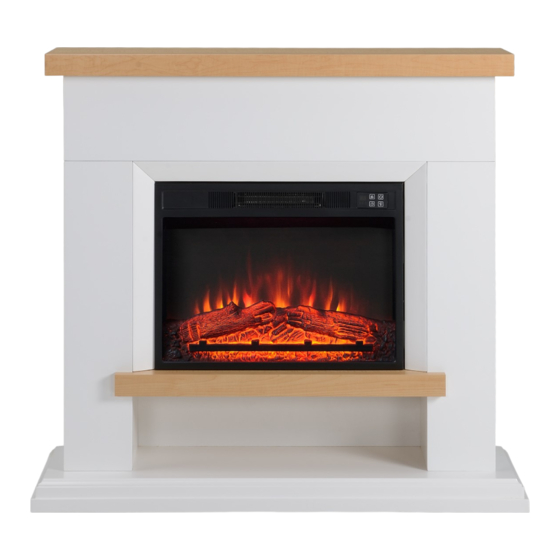
- Page 1 USER AND INSTALLATION MANUAL ELECTRIC FIREPLACE AGL047 Please read this manual before using or installing the electric fire and keep it safe for future reference.
-
Page 2: Table Of Contents
CONTENTS SAFETY PARTS LIST INSTALLATION OPERATION TIMER SETTINGS OPEN WINDOW FUNCTION BATTERY REPLACEMENT TOGGLE SWITCH CARE AND MAINTENANCE TROUBLESHOOTING SUPPORT TECHNICAL SPECIFICATIONS PRODUCT FICHE... - Page 3 SAFETY INFORMATION When using electrical appliances, basic safety precautions should always be followed, including the following: • IMPORTANT: Read all instructions and warnings carefully before starting installation. Failure to follow these instructions may result in a possible electric shock or fire hazard and will void the warranty •...
- Page 4 • Avoid the use of an extension cord, as the cord may overheat and cause a risk of fire. • This fireplace is hot when in use. To avoid burns, do not let bare skin touch hot surfaced. If provided, use handles when moving this appliance. •...
-
Page 5: Safety
ELECTRICAL SAFETY The heater must not be located under an electrical socket; the socket must always be accessible in order to disconnect the heater from the electrical supply for maintenance and cleaning. Important: This heater must be earthed. The mains supply must be safely routed from the heater to an electrical socket. - Page 6 PARTS SUPPLIED (FIREPLACE) NOTE: Pictures and contents in this manual may differ from the product due to continuous product improve. Ensure all parts are accounted for before starting.
- Page 7 Ф7.8 X 30mm Ф7.8 X 40mm Ф4 X 40mm Ф4 X 35mm AX30 DX14 Ф3 X 14mm Ф4 X 24mm FX20 GX24 IX11 AAx1 BBx2 Ф4 X 10mm Ф4 X 6mm CCx6+2 extra DDx6+2 extra...
-
Page 8: Installation
INSTALLATION... - Page 9 Following the image below place 2 cam dowels (E) into the side of part 9 and screw in cams (G) on either side of the of the cam dowels (E), so that parts 7 and 9 and 8 and 9 are connected together. Following the image above screw in 9 screws (I), so that part 11 is on top of part 8, part 13 is on top of part 9 and part 12 is on top of part 7.
- Page 10 Following the image below insert 12x wooden dowels (A) into the sides of 2x part 6. Each part 6 should have 6 wooden dowels (A) respectively. Following the image above screw in 4x screws (D) in to the top face of part 5 and then connect the 2x part 6 to the boom face.
- Page 11 Following the image below place 2x part 6 onto parts 7 and 8 respectively. Then screw 2x cams (G) into 2x part 6 so each part 6 has 1 cam respectively. Following the image above insert 14x wooden dowels (A) into the side of parts 2 and 3 with each part having 7x wooden dowels (A) respectively.
- Page 12 Following the image below place parts 2 and 3 onto parts 8 and 9, 7 and 9 respectively. Then insert 8x cams (G into parts 2 and 3, so that each part has 4 cams (G) and screw using the right-angled Allen key (M). Following the image above screw in 3 dowels (F) onto the flat side of part 10.
- Page 13 Following the image below insert 2x wooden Following the image above line up part 4 to part 7 and 8. Then screw in 10 screws (D) to connect part 4 to parts 7 and 8 with 5 screws (D) respectively.
- Page 14 Following the image below screw the 2 fastening straps (J) into the face of part 1 using the washers (K) and screws (I) provided. Then screw in 7 dowels (F) into the same face of part 1. Following the image above screw in part 14 using 8 screws (H) into the sides of both part 6s. Then screw in part 1 to the top of part 2, part 9, part 3 using 7 cams (G).
- Page 15 Following the image below screw in the top bracket (AA) and 2 side brackets (BB) to the electrical fire using 6 screws (DD), so that each bracket uses 2 screws. Following the image above gently place the fire into the fireplace.
- Page 16 Following the image below screw 6 screws (CC) to secure the fire into the fireplace. CCx6 CCx6 Step Following the image above determine where you will be drilling in the fastening straps and drill 2 holes. Place in the wall plugs (L) and drill in screws (C) through the fastening straps and washers (K).
-
Page 17: Operation
OPERATION NOTE: The manual button on the firebox unit will not provide you with all the function control, and its purpose is to control some basic function when you lose the remote handset. Please use the remote handset to carry out all functions. POWER Turn the unit on or off. -
Page 18: Timer Settings
WEEKLY TIMER SETTINGS • Press Weekly timer Button to enter the weekly timer settings. The display will show “0”. • Press Weekly timer Button a second time until the back digits start flashing, the display shows “1 d” that means the weekly timer start from today. •... -
Page 19: Care And Maintenance
CARE AND MAINTENANCE When cleaning unit, the power supply should be disconnected and the unit should be cool. Dust can be removed by lightly wiping the glass surface with clean, lint free cloth or paper towel. To remove fingerprints or other marks, use a damp cloth with a good quality household glass cleaner. - Page 20 1.There is a level of noise when the flame effect is in use, caused by a motor that helps generate the effect. This noise will be heard when there is no other Fire seems noisy. background noise. 2.There is a higher level of noise associated with the heater motor;...
-
Page 21: Support
Buy It Direct Unit J6, Lowfields Business Park, Lowfields Way, Elland, West Yorkshire, HX5 9DA TECHNICAL SPECIFICATION Description of Product Embedded Electric Fire Model AGL047 Rated Voltage 220-240V~ Rated Frequency 50 Hz Rated Power 1800W~2000W Dimensions (W) x (H) x (D) 58.4 x 12.8 x 43.5 cm... - Page 22 Model Identifier: AGL047 Item Symbol Value Unit Item Unit Heat Output Type of heat input, for electric storage local space heaters only (select one) Nominal heat manual heat charge control, with integrated output thermostat Minimal heat manual heat charge control with room and/or...
Need help?
Do you have a question about the AGL047 and is the answer not in the manual?
Questions and answers