
Related Manuals for Siargo FS35001


Summary of Contents for Siargo FS35001
- Page 1 FS35001 User Manual VA.0.01 MEMS Mass flow sensors for manifold installation ©2022 Siargo Ltd.
- Page 2 Copyright 2022 and Liability Disclaimer Siargo Ltd. and its subsidiaries reserve the right to change the specifications and/or descriptions without prior notice. Siargo and its subsidiaries shall not assume any inaccuracy or errors in this manual. For further information and updates, please visit www.Siargo.com.
- Page 3 • Do not apply for any unknown or non-specified gases that may damage the product. www.Siargo.com FS35001 User Manual...
-
Page 4: Table Of Contents
8.2.3 Excessive humidity or condensation ................20 8.2.4 Metrology verification ....................20 9. Warranty and Liability ................21 10. Service contact and information ............... 23 Appendix I: Sensor evaluation kit ..............24 Appendix II: Document history ............... 25 www.Siargo.com FS35001 User Manual... -
Page 5: Overview
1. Overview This manual provides essential information for the operation of the FS35001 series of gas mass flow sensors for general-purpose gas flow monitor and control applications with the full-scale mass flow rate from 0.2 to 20 SLPM, and both analog and digital outputs. The product performance, maintenance, and troubleshooting as well as the information for product order, technical support, and repair are also included. -
Page 6: Receipt / Unpack Of The Products
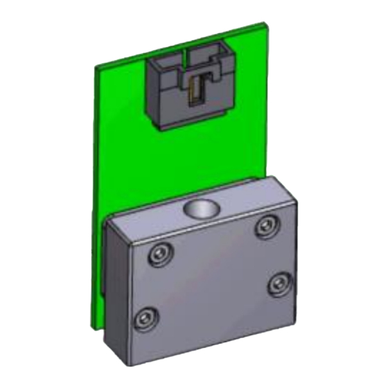
FS35001 Power and data cable (optional) Figure 2.1: FS35001 flow sensor and accessories Please check immediately for the integrity of the product and the power and data cable; if any abnormality is identified, please notify the distributor/sales representative or manufacturer as soon as you can. -
Page 7: Knowing The Products
MTE (5 positions) compatible connector with a length of 0.5 meters. Note: 1. Power supply: The FS35001 requires a power supply of 8 ~ 24 Vdc. No particular requirements for the external power supply, but standard industrial power cautions should be applied. -
Page 8: Mechanical Dimensions
3.3 Mechanical dimensions Figure 3.3.1. FS35001 manifold mechanical dimensions. www.Siargo.com FS35001 User Manual... -
Page 9: Installation
M3x20mm by ISO 14583; the dowel pin should be Φ2m6x6 mm. Please align the products with your gas manifold block properly, and no excessive force should be applied during installation, and subsequent leakage tests would be required for safety and performance. www.Siargo.com FS35001 User Manual... -
Page 10: Basic Operation
The PC UART communication parameters are listed in table 5.1. Table 5.1: PC UART communication parameters Protocol Parameters Baud rate (Bits per second) 38400 bps Start bits Data bits Stop bits Even/Odd parity None Bits period 104.2 µsec Bytes period 1.1458 msec www.Siargo.com FS35001 User Manual... - Page 11 The currently available registers are listed in the following table, and the registers may be customized upon contacting the manufacturer. Where R: read; W: write-only; W/R: read and write. www.Siargo.com FS35001 User Manual...
- Page 12 When the user reads “0” from register 0x003A and “20340” from register 0x003B, current flow rate = (0 * 65536 + 20340) / 1000 = 20.340 SLPM Write Baud rate 0x0082 Read Description Communication baud rate Value type UINT 16 www.Siargo.com FS35001 User Manual...
- Page 13 GCF, or offset, the user needs to send Notes 0xAA55 to the register 0x00FF, and then the write function will be enabled (write protection is disabled). After the write execution is completed, the firmware will automatically re-enable the write protection. www.Siargo.com FS35001 User Manual...
-
Page 14: I 2 C Interface Connection Diagram
5.2 I C communication protocol 5.2.1 I C interface connection diagram 5.2.2 I C interface read/write sequences www.Siargo.com FS35001 User Manual... - Page 15 Value Name CRC-8 Protected data C read and write Width 8 bits Polynomial 0x07 (x8 + x2 + x + 1) Initialization 0x00 Reflect input False Reflect output False Final XOR 0x00 Example CRC(0x4E20) = 0x6D www.Siargo.com FS35001 User Manual...
-
Page 16: Product Selection
Full scale flow rate: 200, 500, 1000, 2000, 4000, 6000, 10000, 15000, and 20000 sccm. For higher flow rate options, please contact the manufacturer. Note: For CO2, the full-scale flow is 60% of the specified ones. www.Siargo.com FS35001 User Manual... -
Page 17: Product Performance
Aluminum alloy; silicon nitride; Ablestik 84-3J; FR4 Note: 1. Allow the product to warm up for 60 seconds for the best performance. 2. Response time shown is the default. It can be programmed to the fastest <2 msec. www.Siargo.com FS35001 User Manual... -
Page 18: Typical (Analog) Output
Figure 7.2: Upper row: from left to right, for models of full scale up to 1000 sccm; and of full scale from 2000 to 6000 sccm. Lower row: models of full scale from 10000 to 15000 sccm (10 to 15SLPM). www.Siargo.com FS35001 User Manual... -
Page 19: Technical Notes For The Product Performance
For medical applications, it may be desired to have the product to be sterilized from time to time. A standard EtO sterilization process is recommended. For the detailed procedure please consult your local experts or contact the manufacturer. 8.2.2 Altitude changes www.Siargo.com FS35001 User Manual... -
Page 20: Excessive Humidity Or Condensation
If such cases are present, please contact the manufacturer for further solutions. For temperature and humidity measurement, because of the small package space, the response of the humidity could be slower than specified. For additional information, please contact the manufacturer. www.Siargo.com FS35001 User Manual... -
Page 21: Warranty And Liability
The products returned under warranty to Siargo shall be at the user or purchaser's risk of loss and will be returned, if at all, at Siargo's risk of loss. Purchasers or users are deemed to have accepted this limitation of warranty and liability, which contains the complete and exclusive limited warranty of Siargo. - Page 22 (5) Any damages incurred by the incorrect usage of the products; (6) Siargo does not provide any warranty on finished goods manufactured by others. Only the original manufacturer's warranty applies;...
-
Page 23: Service Contact And Information
10. Service contact and information Siargo Ltd. is making every effort to ensure the quality of the products. In case of questions and or product support, please contact your direct sales, or in case you need additional assistance, please contact customer service at the address listed below. We will respond to your request in a timely fashion and work with you toward your complete satisfaction. -
Page 24: Appendix I: Sensor Evaluation Kit
Appendix I: Sensor evaluation kit Siargo offers a sensor evaluation kit, including a digital data converter, USB data cable, and User Application software, that allows the user to evaluate the product performance on a Microsoft Windows-based computer. The user can read and visualize the flow rate of the product, obtain the totalized values, and save the data for further analysis. -
Page 25: Appendix Ii: Document History
Appendix II: Document history Revision A.0.01 (July 2022): ➢ Preliminary release. www.Siargo.com FS35001 User Manual...
Need help?
Do you have a question about the FS35001 and is the answer not in the manual?
Questions and answers