Table of Contents
Advertisement
Quick Links
Advertisement
Table of Contents

Related Manuals for Siargo FS4100 Series


Summary of Contents for Siargo FS4100 Series
- Page 1 FS4100 User Manual VA.0 MEMS mass flow sensors ©2021 Siargo Ltd.
- Page 2 User Manual Document No. 08‐2021‐FSN1 EN Issue date: 2021.08 Revision: VA.0 Siargo Ltd. 3100 De La Cruz Boulevard, Suite 210 Santa Clara, CA 95054 USA Tel: +1(408)969.0368 Email: info@siargo.com © Copyright 2021 by Siargo Ltd. Siargo Ltd. and its subsidiaries reserve the right to change the specifications and/or descriptions without prior notice. For further information and updates, please visit: www.Siargo.com www.Siargo.com FS4100 User Manual 1 | P a g e ...
- Page 3 Only the trained or qualified personnel shall be allowed to perform product services. Use with caution! Be cautious for the electrical safety, even it operates at a low voltage, any electrical shock might lead to some unexpected damages. The gas to be measured should be clean and free of particles. Do not apply this meter for liquid medium. Do not apply for any unknown or non‐specified gases that may damage the product. For remote data, please be sure the meter is properly configured. www.Siargo.com FS4100 User Manual 2 | P a g e ...
-
Page 4: Table Of Contents
5.1 Check the product specifications ................ 11 5.2 Check the leakage .................... 11 5.3 Power the product and digital data connection ............ 11 5.4 RS485 Modbus communication protocol .............. 12 .4.1 Hardware connection .................. 12 5.4.2 Communication parameters .................. 12 .4.3 Frame ...................... 13 .4.4 Function codes .................... 13 .4.5 Registers ...................... 13 5.5 Analog output (0.5 ~ 4.5 Vdc) ................. 16 5.6 Pressure loss ...................... 16 Product selection and order information ........... 18 6.1 Product selection .................... 18 6.2 Order contact and customer support ............... 18 Technical specifications ................19 www.Siargo.com FS4100 User Manual 3 | P a g e ... - Page 5 8.2.3 Apply to a different gas medium .................. 21 Troubleshooting .................. 2 2 Warranty and Liability ................ 2 3 Service contact .................. 2 5 Appendix I: Product evaluation kit .............. 26 Appendix II: Document history ............... 2 7 www.Siargo.com FS4100 User Manual 4 | P a g e ...
-
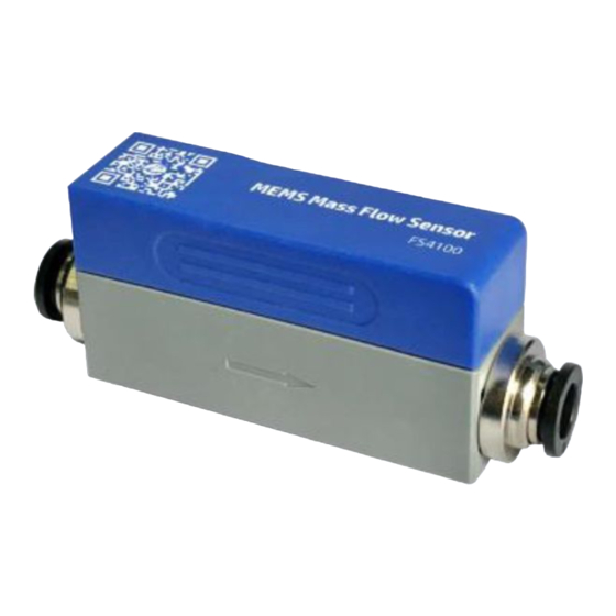
Page 6: Overview
The products are designed with an easy change of mechanical connectors. The standard connectors are BSPT 1/4” or one‐touch connector, and other customized ones are available upon request. The products are operated with Siargo’s proprietary MEMS thermal time‐of‐flight sensing technology together with smart control electronics. The sensor surface is passivated with silicon nitride ceramic materials together with a water/oil proof nano‐coating for performance and reliability. Compared to the previous calorimetric flow sensing technology, this unique sensing ... -
Page 7: Receipt / Unpack Of The Products
This user manual shall also either be included in the packing box or via an online request for an electronic version. In most cases, this manual shall be made available to the customer before the actual order. The standard cable (part number: SN5‐50) has an AMPMODU MTE (5 positions) compatible connector with a length of 0.5 meters. www.Siargo.com FS4100 User Manual 6 | P a g e ... -
Page 8: Knowing The Products
4 Black Ground 5 Yellow A (RS485) / SCL(I C) Figure 3.2: FS4100 connection and cable Note: 1. The standard cable (part number: SN5‐50) has an AMPMODU MTE (5 positions) compatible connector with a length of 0.5 meters. 2. The RS485 Modbus is asynchronous, half‐duplex communication. When the data are transmitted or received from the product, the other pin is serving as the ground. www.Siargo.com FS4100 User Manual 7 | P a g e ... -
Page 9: Mechanical Dimensions
3.3. Mechanical dimensions Figure 3.3: FS4100 dimensions with BSPT 1/4” (R 1/4”) connectors Figure 3.4: FS4100 dimensions with one‐touch connectors Note: * Other threads or compressive types can be customized. ** The mounting screw length <4mm; and the suggested mounting torque <0.25 N∙m. www.Siargo.com FS4100 User Manual 8 | P a g e ... -
Page 10: Installation
(i.e., 8 ~ 24 VDC) and power supply polarization. If an adapter is used, make sure the adapter meets industrial standards and has all safety certifications. Alternatively, this product can also be powered by a 9Vdc battery. f) For the data communication wire connection, please follow the description in Table 3.1 and make sure that the wires are correctly connected to the proper ports on your data device/equipment. Please make sure the data cable meets industrial standards with proper shielding. g) Slowly open the valve(s) of the gas supply if any, upstream or downstream, or both of the pipeline. the product should then start to measure the flow in the pipeline. Note: because the meter has a large dynamical measurement range, it could be normal if you see the small instant flow rate even if there is “no‐flow” in the pipeline. If the value consistently present, double‐check the pipe leakage and then reset the offset if you are sure there is no leakage or flow. h) This will conclude the installation. www.Siargo.com FS4100 User Manual 9 | P a g e ... - Page 11 Cautions a) Don't alter any parts of the product. b) Ensure the electrical connection is properly done per the instructions. c) Make sure no mechanical stresses in the connections. d) The strong electromagnetic interference sources close by or any mechanical shocks at the pipeline may also create malfunctioning of the product. e) Slowly open/close valves at the gas supply piping to prevent abrupt pulse flow impact. www.Siargo.com FS4100 User Manual 10 | P a g e ...
-
Page 12: Operation
A higher voltage may lead to irrecoverable damage, and a lower voltage will not power the product for any desired functions. For the best performance of the product, it is advised that the gas to be measured must be clean and free of particles or other foreign materials. 5.2 Check the leakage Check gas leakage before any measurement. If it is needed, the pressurized nitrogen or air can be used for the leakage check. 5.3 Power the product and digital data connection Although this product complies with the CE‐required EMC regulations, it also requires the product to be used according to the standard electrical device practice. Before connecting the product with external DC power or an AC‐DC adapter, make sure the supply voltage is within the range of the specified ones in Section 7. Be cautious that the standard electrical device precautions such as EDS (electrostatic discharge) and DC voltage are observed. Excessive electrostatic discharge may damage the product. The manufacturer‐supplied power and data cable have a locking fixture. Lock the cable and make sure it is properly engaging and will not be accidentally got unplugged. Half‐duplex RS485 Modbus is used for digital data communication. Make sure the wires are properly connected to the receiver side. www.Siargo.com FS4100 User Manual 11 | P a g e ... -
Page 13: Rs485 Modbus Communication Protocol
5.4.1 Hardware connection The RS485 hardware layer is TIA/EIA‐485‐A, as illustrated below. In this configuration, the product (FS4100) is a slave. Figure 5.1: RS485 hardware 5.4.2 Communication parameters The PC UART communication parameters are listed in table 5.1. Table 5.1: PC UART communication parameters Protocol Parameters RTU Baud rate (Bits per second) 38400 bps Start bits 1 Data bits 8 Stop bits 1 Even/Odd parity None Bits period 104.2 µsec Bytes period 1.1458 msec Maximum data length 20 Maximum nodes 254 www.Siargo.com FS4100 User Manual 12 | P a g e ... -
Page 14: Frame
The Modbus function codes applied for the product are the sub‐class of the standard Modbus function codes. These codes are used to set or read the registers of the product: Table 5.3: function codes Code Name Functions 0x03 Read register Read register(s) 0x06 Set single register Write one single 16‐bit register 0x10 Set multiple registers Write multiple registers 5.4.5 Registers The product (FS4100) has multiple registers available for the assignment of the various functions. With these functions, the user can obtain the data from the products, such as product address and flow rates from the registers, or set the product functions by writing the corresponding parameters. The currently available registers are listed in the following table, and the registers may be customized upon contact the manufacturer. Where R: read; W: write‐only; W/R: read and write. Note: At the time of shipping, the write protection function is enabled except for address and baud rate. Once the user completes the register value change, the write protection will be automatically enabled once again to prevent incidental data loss. www.Siargo.com FS4100 User Manual 13 | P a g e ... - Page 15 SN= value(0x0030), value(0x0031),….,value (0x0035); Notes Receiving 12 bits as: 2A 2A 41 31 42 32 33 34 35 36 2A 2A , the corresponding Serial Number is **A1B23456**. Write N Flow rate 0x003A ~ 0x003B Read Y Description Current flow rate Value type UINT 16 Flow rate = [Value (0x003A) * 65536 + value (ox003B)] / 1000 Notes e.g.: When the user reads “0” from register 0x003A and “20340” from register 0x003B, current flow rate = (0 * 65536 + 20340) / 1000 = 20.340 SLPM Write Y Baud rate 0x0082 Read Y Description Communication baud rate Value type UINT 16 0: baud rate=4800; 1: baud rate=9600; 2: baud rate=19200; 3 baud rate=38400. Notes The default value is 3. e.g.: When the user reads “3” from register 0x0082, the baud rate is 38400. www.Siargo.com FS4100 User Manual 14 | P a g e ...
- Page 16 Write Y Offset calibration 0x00F0 Read N Description Reset or calibrate the offset Value type UINT 16, Fixed value 0xAA55 To reset or calibrate the offset, write 0xAA55 to register 0x00F0. Notes Note: When you execute this function, make sure there is NO flow in the flow channel. Write Y Write protection 0x00FF Read N Description Write protection disabler for a set value to a specific register. Value type UINT 16, Fixed value 0xAA55 This function is enabled at the time of product shipment. To enable the write function of a specific parameter, such as GCF, offset, the user needs to send Notes 0xAA55 to the register 0x00FF, and then the write function will be enabled (write protection is disabled). After the write execution is completed, the firmware will automatically re‐enable the write protection. www.Siargo.com FS4100 User Manual 15 | P a g e ...
-
Page 17: Analog Output (0.5 ~ 4.5 Vdc)
100 % F.S. 4.50 110 % F.S. 4.90 120 % F.S. 4.90 Figure 5.2: FS4100 analog output 5.6 Pressure loss The product is designed for low‐pressure loss. The major drop of the pressure is at the manual valve structure. The following graph illustrated the pressure losses of the selected models. Table 5.6: FS4103 pressure loss Flow rate Pressure loss (SLPM) (Pa / PSI) 0.0 0 / o 1.0 6 / 0.001 2.0 15 / 0.002 3.0 30 / 0.004 4.0 55 / 0.008 5.0 95 / 0.014 Figure 5.3: FS4103 pressure loss www.Siargo.com FS4100 User Manual 16 | P a g e ... - Page 18 Table 5.7: FS4108 pressure loss Flow rate Pressure loss (SLPM) (Pa / PSI) 0.0 0 / o 5.0 8 / 0.001 10.0 25 / 0.004 20.0 90 / 0.013 30.0 200 / 0.029 40.0 370 / 0.054 50.0 580 / 0.084 Figure 5.4: FS4108 pressure loss www.Siargo.com FS4100 User Manual 17 | P a g e ...
-
Page 19: Product Selection And Order Information
Maximum full scale flow rate (for the value refer to the table below). If the unit is not SLPM, the unit needs to be specified here. DN (pipe diameter: 03 or 08) 6.2 Order contact and customer support The sales offices and the sales distributors/representatives are listed at the end of this document. For small quantities, the order can be placed either through the Siargo website: www.siargo.com or the sales office. For large quantities, please contact the sales office, distributors, or sales representatives. Siargo is making every effort to ensure the quality of the products. In case of questions and/or product supports, please contact the customer service listed at the end of the document. www.Siargo.com FS4100 User Manual 18 | P a g e ... -
Page 20: Technical Specifications
C Max. overflow 30 (FS4103) / 200 (FS4108) SLPM Max. flow change 4 (FS4103) / 30 (FS4108) SLPM/sec Electrical connector AMPMODU MTE 5 positions Mechanical connection BSPT or 4mm/6mm/8mm One‐touch Protection IP40 Storage temperature ‐20 ~ 70 °C Reference conditions 20°C, 101.325 kPa, air Fluid compatibility Non‐corrosive CE EN61000‐2; ‐3; ‐4 RoHS/REACH Certified www.Siargo.com FS4100 User Manual 19 | P a g e ... -
Page 21: Technical Notes For The Product Performance
Another key point to compare the different flow meter is that as long as the fluidic flow is a continuous flow without pulsation, then the fluidic dynamic will have the system following the Bernoulli equation: where ρ is the fluid density; g is the acceleration due to gravity; P1 is the pressure of the reference meter; P2 is the pressure at the test meter; v1 is the velocity of the reference meter, and v2 is the www.Siargo.com FS4100 User Manual 20 | P a g e ... -
Page 22: Particle Contamination And Fluidic Cleanness
Gases that can be applied include air, N2, O2, Ar, CO2 and N2O. This innovative product operates also follows the basic sensing principle described in the international standard for thermal mass flow meters (ISO 14511:2001 ‐ Measurement of fluid flow in closed conduits — Thermal mass flowmeters). For gases with different diffusivities, a gas conversion factor could be applied. But due to the meter assembled procedure, the head loss value from the meter to the meter would not be 100% identical, and at the large dynamic measurement range, the thermal response would also have some deviations and nonlinearity from gas to gas. Therefore, measurement by the sensor for a gas medium with a substantially different diffusivities compared to that of the calibration gas would bear larger measurement errors, particularly at the low Reynold number range where the laminar flow has a sensitive flow profile. www.Siargo.com FS4100 User Manual 21 | P a g e ... -
Page 23: Troubleshooting
Phenomena Possible causes Actions Power not connected; battery Connect the power, check the empty cable Cable connection incorrect Check cable No signal No flow or clogging Check flow and contamination Power regulator failure Return to factory Sensor failure Return to factory Large errors or unexpected Particles, fluid type Check system flow rate Erroneous or large noise Vibration, unstable flow Check system Valve not work Wire connection, valve Return to factory Offset unstable Circuitry instability Check system, power off No digital interface Wrong address, software Check commands, connection www.Siargo.com FS4100 User Manual 22 | P a g e ... -
Page 24: Warranty And Liability
Siargo makes no warranty, representation, or guarantee and shall not assume any liability regarding the suitability of the products described in this manual for any purposes that are not specified in this manual. The users shall be held for full responsibility for validating the performance and suitability of the products for their particular design and applications. For any of the misusage of the products out of the scope described herein, the user shall indemnify and hold Siargo and its officers, employees, subsidiaries, affiliates, and sales channels harmless against all claims, costs, damages, and expense or reasonable attorney fee from direct or indirect sources. Siargo makes no other warranty, express or implied, and assumes no liability for any special or incidental damage or charges, including but not limited to any damages or charges due to installation, ... - Page 25 (2) Products that have been subject to chemical attacks, including exposure to corrosive substances or contaminants. In the case of battery usage, long term discharge or leakage induced damages; (3) Products that have been opened or dismantled for whatever reasons; (4) Products that have been subject to working conditions beyond the technical specification as described by this manual or related datasheet published by the manufacturer; (5) Any damages incurred by the incorrect usage of the products; (6) Siargo does not provide any warranty on finished goods manufactured by others. Only the original manufacturer's warranty applies; (7) Products that are re‐sold by unauthorized dealers or any third parties. www.Siargo.com FS4100 User Manual 24 | P a g e ...
-
Page 26: Service Contact
11. Service contact Siargo Ltd. is making every effort to ensure the quality of the products. In case of questions, and or product supports, please contact customer service at the address listed below. We will respond to your request in a timely fashion and will work with you toward your complete satisfaction. Customer service and all orders should be addressed to Siargo Ltd. 3100 De La Cruz Boulevard, Suite 210, Santa Clara, California 95054, USA Phone: +01(408)969‐0368 Email: info@Siargo.com For orders, please provide an accurate and full postal address. Siargo will not ship to P.O. Boxes or via a third party. For further information and updates, please visit www.Siargo.com. www.Siargo.com FS4100 User Manual 25 | P a g e ... -
Page 27: Appendix I: Product Evaluation Kit
The USB Cable to connect cable connected to the PC is also included. to the product For most of the products, the power from the PC via the USB cable will be sufficient to power the sensor product, no external power will be USB cable to required. However, for multiple sensors in serial, connect to PC the power via the USB cable may not be enough, an external power adapter with 8 ~ 24 Vdc will External power be required. adapter (optional) www.Siargo.com FS4100 User Manual 26 | P a g e ... -
Page 28: Appendix Ii: Document History
Appendix II: Document history Revision A.0 (August 2021) First release. Sales Europe : IDENTIC GmbH In der Siedlerruh 24 69123 Heidelberg /Germany Phone: +49 6221 7509 777 Email: info@identic.de www.Siargo.com FS4100 User Manual 27 | P a g e ...
Need help?
Do you have a question about the FS4100 Series and is the answer not in the manual?
Questions and answers