Advertisement
Standard Operating
Procedure (SOP)
Preface
To ensure proper care, operation and many years of accurate measurement, the Standard
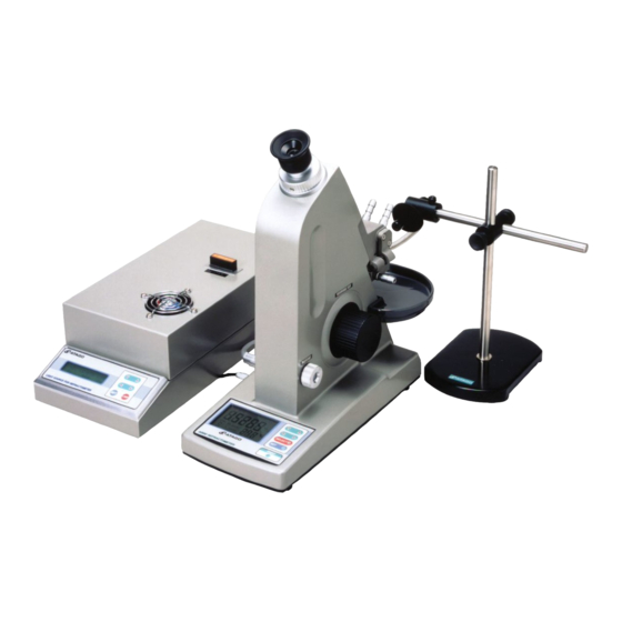
Operating Procedure (SOP) document for the MultiMulti-Wavelength Abbe Refractometer,
DR-M2, is provided herewith.
The following instructions should be used as an example. Based on the steps provided,
write up your company's own original SOP for the operation of the Multi-Wavelength Abbe
Refractometer, DR-M2.
To ensure proper operation, ensure that the main unit of the refractometer and the light
source unit are set up and connected. Also, the 589nm interference filter must be inserted
into the light source unit.
The standard operation procedure document of Multi-Wavelength Abbe Refractometer,
1. Operation Manual
1) Connect a circulating constant temperature bath to the refractometer, and power on.
2) Connect the AC power supply cable of the refractometer to the AC outlet.
Turn on the power supply switch of the DR-M2 and light source unit. The DR-M2
display should indicate [1] and the temperature. The Light source unit display
indicates the wave length and ON/OFF of the LAMP.
3) Drop about 0.1ml of distilled water onto the main prism surface, and gently close the
secondary prism. Set the light guide of the light source unit so that its relative position
is directed at the lighting window of the secondary prism. Press the LAMP key of the
light source unit. The "LAMP" indication on the display of the light source unit
changes to "ON". Press the SET key of DR-M2. Look at the scale through the eyepiece
and turn the measurement knob so that the boundary line is centered at the
intersection point of the cross hairs. Confirm that the temperature is 20.0(±0.2℃). The
display will indicate the refractive index of the sample being measured.
4) Press the SELECT key to display [1] in the mode indicator. Set the function mode
number to [4] with the ∧ key. Press the SET key and the refractive index at the
present boundary line blinks in the display. After confirming that the boundary line is
centered with the intersection point of the cross hairs, press the SET key again.
Press the SELECT key and reset the function mode number to [1] from [4] with the ∨
key. Wipe off the distilled water with a soft, lint-free tissue paper.
5) When measuring a liquid sample, place approximately 0.1ml of the sample onto the
main prism surface, and gently close the secondary prism. Insert the proper
interference filter into the interference filter insertion slot of the light source unit. Set
the light guide of the light source unit so that its relative position is directed at the
lighting window of the secondary prism. Look at the scale through the eyepiece and
turn the measurement knob so that the boundary line is centered at the intersection
point of the cross hairs.
6) The value indicated as the boundary line crosses the intersection point of the cross
hairs is the measurement value of the sample. Wipe off the sample with a soft,
ling-free tissue paper.
7) When measurement is completed, be sure that any sample on the prism surface and
surrounding areas are completely wiped off with tissue paper moistened with water,
then wipe dry with tissue.
8) Turn off the power supply switch of the DR-M2. Confirm that nothing is indicated on
the display section.
9) If used, turn off the power supply switch of the temperature bath.
DR-M2
1/4
Multi-Wavelength Abbe Refractometer
DR-M2
P-SOP0803-1410-E01
Advertisement
Table of Contents

Subscribe to Our Youtube Channel
Related Manuals for ATAGO DR-M2


Summary of Contents for ATAGO DR-M2
- Page 1 The “LAMP” indication on the display of the light source unit changes to “ON”. Press the SET key of DR-M2. Look at the scale through the eyepiece and turn the measurement knob so that the boundary line is centered at the intersection point of the cross hairs.
- Page 2 3. Periodical Inspection Inspect the DR-M2 with a test piece once a month to see if it indicates the measured value correctly. Connect a circulating constant temperature bath to the DR-M2, and set the temperature to 20.0(±0.2℃).
- Page 3 75%. 4) A Desiccant case is installed within the body of the DR-M2. If the indicator inside the desiccant case changes from blue to pink, replace the desiccant, the indicator, and the cushion with new ones.
- Page 4 Perform step 3 (Periodical inspection of the preceding clause). 2) Failure in machinery or parts When the DR-M2 does not operate properly due to mechanical trouble, under the same measuring conditions, degradation of the parts inside the unit and/or failure is assumed.
Need help?
Do you have a question about the DR-M2 and is the answer not in the manual?
Questions and answers