
Related Manuals for ATAGO PRM-100a


Summary of Contents for ATAGO PRM-100a
- Page 1 3574-E16 In-line Refractometer Instruction Manual Cat.No.3574 PRODUCT REGISTRATION & WARRANTY CARD https://www.atago.net/registration/ english/registration.php...
-
Page 3: Table Of Contents
(5) Setting Decimal Place ·············································································································· 44 (6) Scale ON/OFF Set-Up ············································································································· 45 Measurement Procedure ·························································································47 Cleaning the Prism ··································································································48 Definitions of Error Messages ·················································································49 Availability of Parts ··································································································50 Specifications ··········································································································51 Dimensions ··············································································································52 Repair Service and Warranty Period ·······································································53 ATAGO CO.,LTD. Service Centers ··········································································54... -
Page 4: Precautions For Use
1. Precautions for Use Introduction Thank you for purchasing the "In-line refractometer PRM-100α". Before using your PRM-100α, read this instruction manual carefully, and understand how to use it. After reading this manual, keep it on hand for future reference. In this manual "For safe use" describes the important items necessary for safety. Read it carefully. For safe use --- Be sure to observe the following. - Page 5 ◇Do not attempt to repair, modify, or disassemble ◇If the instrument is dropped or is subjected to a the instrument yourself. strong shock, have it inspected by an ATAGO Improper servicing may result in fire, electrical distributor. shock, or burns.
- Page 6 Handling of this instrument (Continued) CAUTION ◇Do not pass corrosive materials over the prism ◇If sample material has collected on the prism, or through the sample inlet unit. please refer to Page 48 "13.Cleaning the Prism" ◇Cleaning liquids up to 160 ˚C can be used for of this manual for cleaning instructions.
- Page 7 Inserting the power plug in any other outlet may If used, fire, electrical shock, or burns may result. result in short circuiting the unit, smoking or fire. For a new power cable and plug, contact your ATAGO distributor. ...
- Page 8 Conditions to be observed when using Environmental conditions ◇Use the instrument at an altitude below 2,000m (above sea level). ◇Use the instrument indoors. ◇Use the instrument where the temperature is between 5 to 40˚C. ◇Do not leave the instrument in a location exposed to direct sunlight or near a heating unit where the temperature may rise.
-
Page 9: Refractive Index And Brix(%)
2. Refractive Index and Brix(%) (1)What is refractometer? When a straw is placed into a glass filled with water, the straw appears to bend. When a straw is placed into a glass filled with sugar water, the straw appears to bend much more sharply than in the case of water alone. -
Page 10: Unpacking And Installation
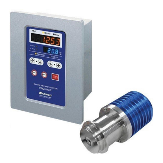
3. Unpacking and Installation (1) Unpacking ①Unpack the unit and visually check for any damages that may have occurred during transit. ②Make sure that the following components are included: PRM-100α detection section ......... 1 PRM-100α calculation display section ....1 ... -
Page 11: Names And Functions Of Components
4. Names and Functions of Components (1)Detection Section (Fig. 4-1 and Fig. 4-2) ①Prism Sample material contacts the prism surface to allow for the measurement of its refractive index, Brix and/or concentration. ②Sample inlet unit mounting part Mount the sample inlet unit on this part. ③Detection section - Display section connection terminal Connect the DS-2 cable to this terminal. -
Page 12: Display Section
(2)Display Section (2-1) Operator section (Fig. 4-3) ①START/STOP key ⑥Measurement indicator Start or stops measurement (turning the Indicates the current mode of measurement; power on automatically begins that is continuous or halted. measurement). During use, the yellow light is blinks. ②SCALE key ⑦SET UP mode indicator Chooses from among the measurement value... - Page 13 (2-2) Rear section (Fig. 4-4) ①Power key Press to turn on the calculation display section. ②Alarm output terminal Use to handle alarm signals. ③RS-232C output terminal Use to connect the calculation display section to a personal computer. ④Recorder output terminal Use to connect the calculation display section to a recorder.
-
Page 14: Mounting The Detection Section
5. Mounting the Detection Section ◇Turn the power switch on the display section to OFF and unplug it from the AC outlet prior to mounting the detection section. WARNING Mounting the detection section with the unit turned on may increase the likelihood of electric shock. -
Page 15: Mounting The Sample Inlet Unit (Fig. 5-2)
(2)Mounting the Sample Inlet Unit (Fig. 5-2) Fit the sample inlet unit into the leading section of the detection part, and secure the sample inlet unit with the attached clamp and O-ring provided. O-ring (silicon or EPDM) O-ring (silicon or Clamp EPDM) Fig. -
Page 16: Mounting On The Piping (Main) (In The Case Of L Type)
(3) Mounting on the Piping (main) (in the case of L type) Mount the detection section on the piping, observing the flow direction of the fluid to ensure it will hit the prism surface of the detection section (Fig. 5-4). Fluid flow Fig. -
Page 17: Mounting The Display Section
6. Mounting the Display Section ◇Turn the power switch of the display section to OFF and unplug it from the AC outlet prior to mounting the detection section. WARNING Mounting the detection section with the unit turned on may increase the likelihood of electric shock. - Page 18 φ11.5 Accessories: Hexagon bolt ·················· 2 Spring washer Plain washer Plain washer ··················· 4 Hexagon bolt M6×12 Fig. 6-2 Table 6-1 Panel thickness Plain washer Schematic 2pcs 2pcs 1pcs...
-
Page 19: Connecting The Detection Section To The Display Section
7. Connecting the Detection Section to the Display Section ◇Turn the power switch of the display section to OFF and unplug it from the AC outlet prior to attaching or detaching the DS-2 cable to or from the WARNING terminal. - Page 20 Detection section Front of the calculation display section Back of the calculation display section DS-2 cable for connecting the display and detection sections Fig. 7-2...
-
Page 21: External Output
8. External Output ◇Turn the power switch of the display section to OFF and unplug it from the AC outlet prior to attaching or detaching the DS-2 cable to or from the WARNING terminal. The display section contains three external output ports: a recorder output (4 to 20mA) port, an RS-232C output port, and an alarm output cable port (Fig. -
Page 22: Rs-232C Output
(2)RS-232C Output This unit provides RS-232C outputs for use with a PC via an external output port installed on the rear panel of the calculation display section. Use the exclusive connecting cable (option) to collect RS-232C outputs. Keep the calculation display section and PC at most 15m apart. ①Dedicated cable specifications (Fig. -
Page 23: Alarm Output (High- And Low-Limiter Output)
(3) Alarm Output (high- and low-limiter output) The alarm output functions based on the established range of acceptable measurement values. When a value is detected that falls outside of the acceptable range alarm output is transmitted from the detection section. The high-limiter and low-limiter output circuit has a photocoupler with a transistor open collector in the final stage. -
Page 24: Turning On The Power
◇Do not use power cables that are damaged, broken or modified. Use of such cables may increase the likelihood of fire, electrical shock or burns. Contact ATAGO or an authorized ATAGO distributor for repair or replacement cables. ◇Do not handle plugs with wet hands. -
Page 25: Setting Measurement Value Display Modes
10. Setting Measurement Value Display Modes (1) Common Operation When the unit is measuring a sample, use the START/STOP key to stop measurement. During measurement, keys other than the START/STOP key are disabled. Measurement must first be stopped to change the scale. ... -
Page 26: Change From Brix Mode To Nd
(3) Change from Brix Mode to nD ①During measurement, the READING light blinks, and the display will show Brix (%) readings (Fig. 10-4). By pressing the START/STOP key, the READING light will turn off, and "StoP" will display, ceasing measurement (Fig. 10-2). The "Brix (%)"... -
Page 27: Confirmation Of Measurement Values At Each Mode
From Brix SET UP SCALE SCALE SCALE SCALE SCALE SCALE Conc1 Conc2 Conc3 Conc4 Conc5 ↓ ↓ ↓ ↓ ↓ ⇒ ⇒ ⇒ ⇒ ⇒ ⇒ 18.87 LLLLLL ---- 1.33299 ↓ ENTER ↓ ENTER ↓ ENTER ↓ ENTER ↓ ENTER The "Conc"... -
Page 28: Setting Measurement Set Up Mode
11. Setting Measurement SET UP Mode (1) Calibration Procedure ①Make sure that the detection section (sample inlet unit) is properly mounted on the piping. ②Let distilled water or a reference sample flow into the piping. ※ If the last measurement value was LLLL.LL or HHHH.HH, the screen for setting the bias will not appear. - Page 29 ⑧Press the ENTER key to access the SET UP mode. The most recent measurement value will be displayed. ※ If the last measurement value was LLLL.LL or HHHH.HH, the screen for setting the bias will not appear. Press the SCALE key to return to the previous "1. bIAS"...
-
Page 30: Setting Alarms
(2) Setting alarms ①Choose the measurement scale for which the alarm is to be set (nD, Brix, or CONC 1 to 5). The example below is for setting the alarm in Brix measurement mode. ② Press the START/STOP key to pause the measurement. -
Page 31: Setting Recorder Output
(3) Setting recorder output ① Press the START/STOP key to pause the measurement. ②Press the SCALE key three times. The SET UP light will then blink, and "SEt" will be displayed on the measurement value display. ③Press the ENTER key and the SET UP light comes Using the ↑... -
Page 32: Setting Conc (User Scale)
(4) Setting Conc (User Scale) In addition to the nD and Brix scales, this unit is equipped with Conc mode. This is the User Scale, the feature that allows the user to display the sample Concentration of their choice. To program a user scale, create a conversion table showing the refractive index of the sample and the Concentration at various temperatures. - Page 33 (4-2) Creating Data Table (4-2-1) Definition and Format of Data Table ① The data table consist of the following three definitions: temperature, Refractive Index, and Concentration. ②The maximum number of data points possible is: 6 for temperature and 7 for Concentration. ③The temperature is displayed by 3 digits and 1 decimal place (000.0).
- Page 34 This chapter explains the procedure of creating a data table for caustic soda (NaOH) solutions. [Items to prepare] ・ATAGO RX-5000α Cat.No. 3261 - A precision refractometer (with an internal constant temperature feature, if possible) ・A circulating constant temperature bath (unnecessary for a refractometer with an internal constant temperature feature) ・Sample solutions of different concentrations (example: NaOH solutions)
- Page 35 (4-3) Transferring Data A data table needs to be re-formatted for the user scale to be transferred to the PRM-100α. Save the data in the format of a text editor for Windows. Connect the computer and the calculation display section via the designated RS-232C cable and transfer the data.
- Page 36 (4-3-3) Creating Text File ① Start up a personal computer installed with Windows. Click the Start button at the bottom left of the screen. ②Click program. ③ Click Accessories. ④ Click Notepad. ⑤ The Notepad should appear (Fig. 11-13). Fig. 11-13...
- Page 37 ⑥Create a text file as in Fig. 11-14 based on Data Table 11-2. Enter everything with half-sized characters. See Fig. 11-15 for meaning of individual numeric values. When completed, it becomes the screen of Fig. 11-16. Moreover, TAB codes are not displayed on the screen, so move the blinking cursor character by character and check the number of TAB codes.
- Page 38 Examples of entry If you enter concentrations as 0.0%, 10.0%, 20.0%, enter 1 for the number of display digits of a concentration. If you enter concentrations as 10.000%, 20.000%, 30.000%, enter 3 for the number of display digits of a concentration.
- Page 39 ⑦Once the data entry is complete (Fig. 11-16), save the file. Fig. 11-17 ⑧ Open the file to make sure that the complete data are saved. Click on File and then Exit to close (Fig. 11-18). A text file has been successfully created. Fig.
- Page 40 (4-4) Preparing a PC for Data Transmission Download a terminal emulator for PC serial communication. Here, the open-source software “Tera Tarm” is used as an example. ※When the PC does not have a 9-pin D-sub connector, purchase a USB/serial adapter. RE-55202 :...
- Page 41 ③ The serial settings are conformed to the instrument settings. Enter the port number selected in step 1. Click OK. ④ Click Setup, and then Terminal port. ⑤ Enter the settings as shown below and Click OK. ※ Make sure that the "Local echo" is checked.
- Page 42 (4-5) Preparing PRM-100αfor Data Reception ①Select "4. Conc" on the SET UP mode, using the ↑ ↓ keys (Fig. 11-20). Fig. 11-19 ②Press the ENTER key to confirm the selection. The screen is ready for Conc1 to 5. (Fig. 11-20). Conc1 Fig.
- Page 43 (4-6) Transferring Data When preparations for sending (computer side) and preparations for receiving (PRM-100αside) are completed, send the created text file (NaOH solution) according to the following steps. Saving received data to a local file: Click “File” and “Log…” and a “Tera Term: Log” window will appear. Save with a desired file name. ①Window for Tera Tarm comes out on the screen.
- Page 44 ②Click on ▼ next to [Look in:] to select the hard disk drive storing a created user scale file (Fig. 11-23). A. Move the cursor to ▼ and click on it with the left button of your mouse. B. As a menu screen like this opens, specify the hard disk drive storing the user scale created earlier with Notepad.
- Page 45 ④Next, enter the file name of the created user scale in the blank next to File name. A. Move the cursor to the user scale name and click on it with the left button of your mouse. B.The user scale name will be automatically entered in the blank next to File name. C.If the user scale name is entered next to File name, move the cursor to Open and click on it with the left button of your mouse.
-
Page 46: Setting Decimal Place
(5) Setting Decimal Place ① Press the START/STOP key to pause the measurement. ②Press the SCALE key three times. The SET UP light will then blink, and "SEt" will be displayed on the measurement value display. ③Press the ENTER key and the SET UP light comes Using the ↑... -
Page 47: Scale On/Off Set-Up
(6) Scale ON/OFF Set-Up This setting is for displaying only the particular scale(s) used on a regular basis. For example, to display only "Brix" and "Conc1 (concentration)" : select "ON" for the 2 aforementioned scales and "OFF" for all other scales. Press the SCALE key again to display only "Brix,"... - Page 48 ↑ ↓ keys 6.CH From ENTER Key ●nD 〇Brix(%) 〇Conc ●nD 〇Brix(%) 〇Conc nD ENTER Key 〇nD ●Brix(%) 〇Conc 〇nD ●Brix(%) 〇Conc Brix ENTER Key 〇nD 〇Brix(%) ●Conc 〇nD 〇Brix(%) ●Conc Conc1 ENTER Key 〇nD 〇Brix(%) ●Conc 〇nD 〇Brix(%) ●Conc Conc2 ENTER Key 〇nD...
-
Page 49: Measurement Procedure
AC outlet. WARNING Continued use could increase the risk of fire or failure. Contact your ATAGO distributor for servicing information. ◇Avoid unauthorized repairs or modifications, as these could increase the likelihood of fire, electrical shock or burning hazards. -
Page 50: Cleaning The Prism
13. Cleaning the Prism ◇Handle all harmful substances with extreme caution. Fully understand a sample's properties before applying to this instrument. WARNING Ensure no harmful sample substances are present when dismantling. Temperature of the cleaning liquid ◇Cleaning liquids up to 160˚C can be used for CIP or SIP. The momentary CAUTION difference between the sample liquid temperature and the cleaning liquid temperature must be no more than 80˚C. -
Page 51: Definitions Of Error Messages
14. Definitions of Error Messages Measurement value display Error message Explanation Action L.LLLLL In Refractive index (nD) mode, the sample measured Measure a sample within the measuring below the lower limit of the measuring range, or range. measurement was made with air contacting the prism. -
Page 52: Availability Of Parts
15. Availability of Parts The table below lists the customer-serviceable and expendable parts for this unit. For their availability, contact your ATAGO distributor. Part name Part number Summary RS-232C output cable RE-65301 4-pin connector, D-Sub connector on one end, standard 10mm. -
Page 53: Specifications
16. Specifications The standard specifications of this product are summarized below. Measurement items One of Refractive Index (nD), Brix (temperature compensation according to sucrose solution),and concentration (%)1to5 (temperature compensation according to samples). Temperature Measuring range Refractive Index (nD) 1.32000 to 1.55700, Brix 0.00 to 100.00% Minimum indication Refractive Index (nD) 0.0001 or 0.00001, Brix 0.1%... -
Page 54: Dimensions
17. Dimensions Detection section (Weight : 3.2kg) Display section (Weight : 3.3kg) 156.6 183.6 (40) (31.8) (22.5) 2-φ6.5... -
Page 55: Repair Service And Warranty Period
The warranty of this unit is one year after the date of purchase. Any trouble detected during the warranty period will be performed without charge. After the warranty has expired, the cost of repairs will be subject to evaluation. Ask your ATAGO distributor concerning this matter. -
Page 56: Atago Co.,Ltd. Service Centers
19. ATAGO CO.,LTD. Service Centers ATAGO has Authorized Service Centers around the world. Below is the list of countries where you can find an ATAGO Authorized Service Center. If your ATAGO instrument requires servicing please contact ATAGO at the following e-mail address. - Page 57 Headquarters: The Front Tower Shiba Koen, 23rd Floor 2-6-3 Shiba-koen, Minato-ku, Tokyo 105-0011, Japan TEL: 81-3-3431-1943 FAX: 81-3-3431-1945 overseas@atago.net http://www.atago.net/ TEL: 1-425-637-2107 customerservice@atago-usa.com TEL: 91-22-28544915 / 40713232 customerservice@atago-india.com TEL: 66-21948727-9 ,66-21171549 customerservice@atago-thailand.com TEL: 55 16 3913-8400 customerservice@atago-brasil.com TEL: 39 02 36557267 customerservice@atago-italia.com...
Need help?
Do you have a question about the PRM-100a and is the answer not in the manual?
Questions and answers