Table of Contents
Advertisement
Quick Links
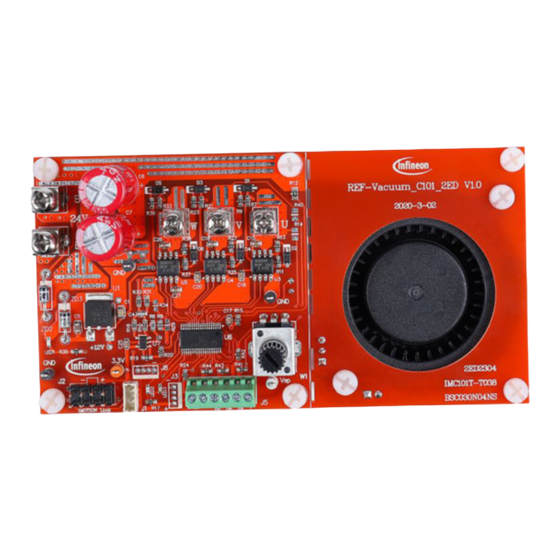
UG2020-11 REF-Vacuum-C101-2ED User Guide
REF-Vacuum-C101-2ED User Guide
SOI driver & Vacuum Application Reference Design Kits
About this document
Scope and purpose
This user guide provides an overview of the reference board REF-Vacuum-C101-2ED including its main features,
key data and mechanical dimensions.
REF-Vacuum-C101-2ED is a full-featured starter kit, turnkey low-voltage motor drive designed for high-
performance, high-efficiency PMSM/BLDC motor drive applications, including all of the required elements for
vacuum applications, such as IMC101T iMOTION
BSC030N04NS OptiMOS
The starter kit features and demonstrates Infineon's thin-film SOI technology and advanced motion control
engine (MCE 2.0) technology for low-voltage, permanent-magnet motors drive up to 120 kRPM speed, and
inverter section up to a rating of 30 V and 25 A. It is optimized for major low-voltage home appliances like
vacuums, fans, pumps, compressors and other low-voltage motor drive applications.
Intended audience
This application note is intended for all technical specialists who are familiar with high-speed motor control
and low-voltage electronics converters. The reference design is intended to be used under laboratory
conditions only by trained specialists.
Ordering information
Base Part Number
REF-VACUUM-C101-2ED
IMC101T-T038
BSC030N04NS G
2ED2304S06F
User Guide
www.infineon.com
.
TM
Package
EVAL
PG-TSSOP-38-9
PG-TDSON-8
PG-DSO-8
Please read the Important Notice and Warnings at the end of this document
controller, 2ED2304S06F SOI half-bridge gate driver and
TM
Standard Pack
Form
Quantity
Boxed
1
Tape and Reel
3000
Tape and Reel
5000
Tape and Reel
2500
page 1 of 43
Orderable Part Number
REFVACUUMC1012EDTOBO1
IMC101TT038XUMA1
BSC030N04NSGATMA1
2ED2304S06FXUMA1
Revision 1.0
2020-05-22
Advertisement
Table of Contents

Related Manuals for Infineon REF-Vacuum-C101-2ED


Summary of Contents for Infineon REF-Vacuum-C101-2ED
-
Page 1: About This Document
SOI driver & Vacuum Application Reference Design Kits About this document Scope and purpose This user guide provides an overview of the reference board REF-Vacuum-C101-2ED including its main features, key data and mechanical dimensions. REF-Vacuum-C101-2ED is a full-featured starter kit, turnkey low-voltage motor drive designed for high-... -
Page 2: Table Of Contents
The detailed features and functions of 2ED2304 ................. 14 Tolerant to negative transient voltage on V pin (-VS) ................. 14 Getting started with REF- Vacuum -C101-2ED ................16 Hardware description of REF-Vacuum-C101-2ED ............... 22 Inverter section ............................. 22 6.1.1 DC bus sensing and MCEWizard configuration ................24 6.1.2... -
Page 3: Important Notice
Infineon Technologies. The design of the Reference Boards has been tested by Infineon Technologies only as described in this document. The design is not qualified in terms of safety requirements, manufacturing and operation over the entire operating temperature range or lifetime. - Page 4 UG2020-11 REF-Vacuum-C101-2ED User Guide Infineon Technologies reserves the right to modify this document and/or any information provided herein at any time without further notice. User Guide www.Infineon.com/iMotion 4 of 43 www.Infineon.com/SOI Revision 1.0 2020-5-22...
-
Page 5: Safety Precautions
DC supply, or excessive ambient temperatures may result in system malfunction. Caution: REF-Vacuum-C101-2ED reference board is shipped with packing materials that need to be removed prior to installation. Failure to remove all packing materials that are unnecessary for system installation may result in overheating or abnormal operating conditions. -
Page 6: Introduction
UG2020-11 REF-Vacuum-C101-2ED User Guide Introduction The REF-Vacuum-C101-2ED is part of the iMOTION™ reference design kits. It is designed to provide ready-to- use, low-voltage and high-speed vacuum solutions based on Infineon’s thin-film SOI technology and advanced motion control engine (MCE 2.0) technology. It allows fast prototyping and fast time to market. The board is equipped with all assembly groups for sensorless field-oriented control (FOC), and reserved interface for three digital Hall sensors, so that it can be extended to other low-voltage and high-current motor applications. -
Page 7: Ref-Vacuum-C101-2Ed Main Features
UG2020-11 REF-Vacuum-C101-2ED User Guide REF-Vacuum-C101-2ED main features REF-Vacuum-C101-2ED is a reference design for 24 V (like 6~7S Li battery) low-voltage motor drive applications. Main features of SOI half-bridge gate driver 2ED2304S06F include: • Infineon thin-film SOI technology • Fully operational to +650 V, floating channel designed for bootstrap operation •... -
Page 8: Ref- Vacuum -C101-2Ed Board Specifications
UG2020-11 REF-Vacuum-C101-2ED User Guide REF- Vacuum -C101-2ED board specifications Table 2 depicts the key specifications of the reference design REF-Vacuum-C101-2ED. Table 2 REF-Vacuum-C101-2ED board specifications Parameters Values Conditions / comments Input Voltage 18 - 30 V 6S ~ 7S Li battery or 24VDC input... - Page 9 UG2020-11 REF-Vacuum-C101-2ED User Guide Figure 2 points out the functional groups on the top side of the REF-Vacuum-C101-2ED reference design 1. 24 V DC input connector 2. iMOTION link connector, UART 0 & UART1 3. DIR, Duty/Freq PWM input connector 4.
-
Page 10: Connector Pin Assignment
UG2020-11 REF-Vacuum-C101-2ED User Guide Figure 3 points out the functional groups on the bottom side of the REF-Vacuum-C101-2ED reference design 11. UVW inverter MOSFET 12. Anti-reverse connection protection 13. On-board cooling fan ON/OFF Jumper Figure 3 Functional groups of the bottom side of REF-Vacuum-C101-2ED reference design... - Page 11 UG2020-11 REF-Vacuum-C101-2ED User Guide Table 4 denotes the details of the UART related connector (iMOTION Link connector J2, J1 & J8) Table 4 J2- iMOTION link connector S. No. Details TXD1 User UART for Script communication (Same as J8 Pin3)
-
Page 12: Product Overview Of 2Ed2304S06F
Moreover, higher time accuracy of the motor current sampling also requires gate drivers to deliver delay matching as low as possible. International Rectifier was the first innovator of junction isolation technology and Infineon is now continuing the history of innovation with its unique SOI technology for high voltage. Infineon’s SOI-based level-shift... -
Page 13: Internal Block Diagram
UG2020-11 REF-Vacuum-C101-2ED User Guide Internal block diagram Figure 4 illustrates the internal block diagram of the 2ED2304S06F. Boostrap diode BIAS NETWORK - VB LATCH GND / PGND HV LEVEL-SHIFTER COMPA Gate- LEVEL- + REVERSE-DIODE RATOR Drive SHIFTER DETECT DETECT Gate-... -
Page 14: The Detailed Features And Functions Of 2Ed2304
UG2020-11 REF-Vacuum-C101-2ED User Guide The detailed features and functions of 2ED2304 Infineon thin-film-SOI technology, high reliability and lower power loss Fully operational to +650 V Output source/sink current capability +0.36 A/-0.7 A Floating channel designed for bootstrap operation ... - Page 15 UG2020-11 REF-Vacuum-C101-2ED User Guide however, a high side output transition from low to high when the low side is on can cause switch damage or unreliable motor operation. Negative V excursions occur during faster switching events over long PCB traces or wiring harnesses that form a parasitic inductor.
-
Page 16: Getting Started With Ref- Vacuum -C101-2Ed
After downloading and installing the iMOTION™ PC tools, MCEWizard and MCEDesigner, the following steps need to be executed in order to run the motor. Refer to MCEWizard and MCEDesigner documentation for more information. Figure 8 shows the basic system connection using REF-Vacuum-C101-2ED to run a vacuum motor with sensorless mode: Motor Phase... - Page 17 UG2020-11 REF-Vacuum-C101-2ED User Guide MCEWizard welcome page and MCEDesigner Figure 9 User Guide www.Infineon.com/iMotion 17 of 43 www.Infineon.com/SOI Revision 1.0 2020-5-22...
- Page 18 (IMC101T_Vxxx.irc file is included in downloaded “IMC101T MCE Software Package”) 7. MCEDesigner should automatically connect to the REF-VACUUM-C101-2ED board using default COM port (Indicated by green circle next to “COMx Up” status in the bottom frame of the MCEDesigner GUI). If it cannot User Guide www.Infineon.com/iMotion...
- Page 19 UG2020-11 REF-Vacuum-C101-2ED User Guide establish the connection due to incorrect COM port, change COM port by doing the following steps: click on the “System Page” window and then click on “Preferences > Connection > Connect using”, and choose one of the other available COM ports from the drop-down list.
- Page 20 UG2020-11 REF-Vacuum-C101-2ED User Guide 10. Double click “VF Diagnostic” function in motor1 page, monitor motor current with oscilloscope. If motor current is not sinusoidal, change target speed and Vd_Ext in VF Diagnostic sub-function, then double-click “VF Diagnostic” until oscilloscope shows a steady sinusoidal current, with amplitude of 30~50% motor rate current.
- Page 21 UG2020-11 REF-Vacuum-C101-2ED User Guide Trace waveform for Iu & Flx-M at 50% speed Figure 14 14. Once the firmware has been programmed, in case a new parameters’ file has to be programmed, follow the same instructions given in step 9. In this case, firmware programming is no longer needed and it is possible to select the first option “Program Parameters.”...
-
Page 22: Hardware Description Of Ref-Vacuum-C101-2Ed
Hardware description of REF-Vacuum-C101-2ED The REF-Vacuum-C101-2ED board is an optimized design for 6S ~ 7S Li battery power vacuum applications, which can be used for different voltages (outside the range of 18 V~30 V) or different power classes (well below 600 W), by replacing different MOS, current-sensing resistors and by modifying auxiliary power supply. - Page 23 UG2020-11 REF-Vacuum-C101-2ED User Guide Figure 16 ON-time test waveform Figure 17 OFF-time test waveform User Guide www.Infineon.com/iMotion 23 of 43 www.Infineon.com/SOI Revision 1.0 2020-5-22...
-
Page 24: Dc Bus Sensing And Mcewizard Configuration
DC bus sensing and MCEWizard configuration Figure 18 provides the DC bus sense resistor details on the REF-Vacuum-C101-2ED reference design. The high-side resistor is 100 kOhm and the low-side resistor is 10 kΩ; 0 ~ 36.3 V DCBUS reflecting 0 ~ 3.3 V at the ADC input pin with 3.3 V power supply, and 0~55 V for 5 V power supply (by replacing U2 to 5V LDO). -
Page 25: External Op-Amp Configuration And Calculation For Current Feedback
A 2 mOhm 3 W 2512 package shunt resistor and 10X external-gain operational amplifier (op-amp) is the default configuration for the REF-Vacuum-C101-2ED reference design, which means 1 A DC bus current produces 20 mV voltage to ADC input, MCEWizard’ s “Motor1 Current Input Scaling” needs input of 20 mV/A. -
Page 26: Configuration And Calculation For Direct Current Sensing
UG2020-11 REF-Vacuum-C101-2ED User Guide Negative current range sensing range is 300 mV/op-amp gain/RS1, corresponding to regeneration current limit in MCEWizard (parameters of RegenLim) If 3X ADC internal gain is selected, there is 800 mV range for motoring condition current sensing (3300 mV/3 –... - Page 27 UG2020-11 REF-Vacuum-C101-2ED User Guide �� 5.1�� ���� ���������� = ���� ∗ �� ���� ∗ �� 0.98 ∗ ���� ∗ �� ������ ������ ������ �� + �� 5.1�� + 0.1�� Figure 23 Current feedback without external op-amp R29 & R34 also determine the ADC operational bias for current sensing, which corresponds to the motor regeneration operation range.
-
Page 28: Inverter Overcurrent Protection And Motor Gatekill Configuration
UG2020-11 REF-Vacuum-C101-2ED User Guide Maximum DCBUS input current of inverter (I ) is 3 A, and already includes 20~30% overload margin Shunt resistor rate power is 1 W (low cost of thin film 2512 package), 60% derating (allow maximum 0.6 W) The shunt resistor power rating is calculated by the following equation. - Page 29 UG2020-11 REF-Vacuum-C101-2ED User Guide C: Offset of the external op-amp or RC divider Figure 24 Overcurrent protection circuit on the REF-Vacuum-C101-2ED reference design User Guide www.Infineon.com/iMotion 29 of 43 www.Infineon.com/SOI Revision 1.0 2020-5-22...
-
Page 30: Ntc Thermistor Characteristics And Overheat Protection Calculation
UG2020-11 REF-Vacuum-C101-2ED User Guide Figure 25 Overcurrent protection setup in MCEWizard Normally it is recommended to set a value higher than motor maximum peak current (maximum RMS current * 1.414) in “Device Overcurrent trigger level setting for Comparator”, with a reserve of at least 30% margin, especially for ultra-low impedance motors, of which peak saw tooth current would trigger unwanted overcurrent fault. -
Page 31: External Ntc Thermistor Characteristics
UG2020-11 REF-Vacuum-C101-2ED User Guide Figure 26 Over-temperature protection enabled in MCEWizard 6.2.1 External NTC thermistor characteristics The NXFT5WF104 thermistor’s B-constant is 4250, typical resistance and output of temperature-sensing voltage listed in Table 9. Table 9 NTC – Thermistor Characteristics Temperature... - Page 32 UG2020-11 REF-Vacuum-C101-2ED User Guide The pull-up resistor is 10 k, and IMC101T’s temperature-related AD input voltage is shown in Figure 27. 3250 3000 NTC OUTPUT 2750 2500 2250 2000 1750 1500 1250 1000 1 0 0 1 2 0 1 4 0...
-
Page 33: Auxiliary Power Supply
Auxiliary power supply Figure 29 depicts the schematic of the auxiliary power supply for the REF-Vacuum-C101-2ED board. Two linear LDO used for 12 V and 3.3 V power supply. U2 can be replaced by 5 V LDO or adjustable IFX1117ME V to achieve higher power supply, for the application that needs higher SNR of motor current sample with external OPA. - Page 34 UG2020-11 REF-Vacuum-C101-2ED User Guide Figure 30 Schematics for REF-Vacuum-C101-2ED User Guide www.Infineon.com/iMotion 34 of 43 www.Infineon.com/SOI Revision 1.0 2020-5-22...
-
Page 35: Pcb Layout For Ref-Vacuum-C101-2Ed
PCB is removed. The thickness of the PCB board is 1.6 mm. Contact our technical support team for more detailed information and the latest Gerber files. Figure 31 illustrates the top assembly print of the reference design. Figure 31 Top assembly print of the REF-Vacuum-C101-2ED reference design User Guide www.Infineon.com/iMotion 35 of 43 www.Infineon.com/SOI... - Page 36 UG2020-11 REF-Vacuum-C101-2ED User Guide Figure 32 depicts the bottom assembly print of the reference design. Figure 32 Bottom assembly print of the REF-Vacuum-C101-2ED reference design The top layer routing of the PCB is provided in Figure 33 . Figure 33...
- Page 37 UG2020-11 REF-Vacuum-C101-2ED User Guide Figure 34 illustrates the bottom layer routing of the PCB. Figure 34 Bottom layer routing of the REF-Vacuum-C101-2ED User Guide www.Infineon.com/iMotion 37 of 43 www.Infineon.com/SOI Revision 1.0 2020-5-22...
-
Page 38: Thermal Characterization
UG2020-11 REF-Vacuum-C101-2ED User Guide Thermal characterization Figure 35 shows the thermal characterizations of REF-Vacuum-C101-2ED, based on 2 layers of FR4 PCB, as shown in Figures 31~34. The tests reported were performed under the following conditions: t =25° C, Vdc = 24 V, different phase current values until the MOS case reaches 105 °... -
Page 39: Bill Of Material
UG2020-11 REF-Vacuum-C101-2ED User Guide Bill of material Table 10 provides the complete bill of materials for the REF-Vacuum-C101-2ED. Table 10 Bill of materials No. Qty Part description Designator Part number Manufacturer C1, C8, C11, C38, CAP CER 10μF 25V X5R 0805... - Page 40 UG2020-11 REF-Vacuum-C101-2ED User Guide No. Qty Part description Designator Part number Manufacturer RES SMD 220 kOhm 1% 1/10W 0603 AR0603FR-07220KL RES SMD 15 Ohm 5% 1/10W R9, R13, R23, R27, 0603 R36, R38 AR0603JR-0715RL RES SMD 1 kOhm 1% 1/10W...
-
Page 41: Reference
All the Datasheets and documents for SOI gate drivers are available at www.Infineon.com/SOI Attention: Infineon’s product registration is now done online. You can register your board and download further information. There are three easy steps to register: Go to www.Infineon.com/ login to myinfineon Click on “Product Registration”... - Page 42 UG2020-11 REF-Vacuum-C101-2ED User Guide User Guide www.Infineon.com/iMotion 42 of 43 www.Infineon.com/SOI Revision 1.0 2020-5-22...
- Page 43 WARNINGS 81726 Munich, Germany Due to technical requirements products may contain dangerous substances. For information on the types in question please contact your nearest Infineon © 2020 Infineon Technologies AG. Technologies office. All Rights Reserved. Except as otherwise explicitly approved by Infineon...
Need help?
Do you have a question about the REF-Vacuum-C101-2ED and is the answer not in the manual?
Questions and answers