Table of Contents
Advertisement
Quick Links
`
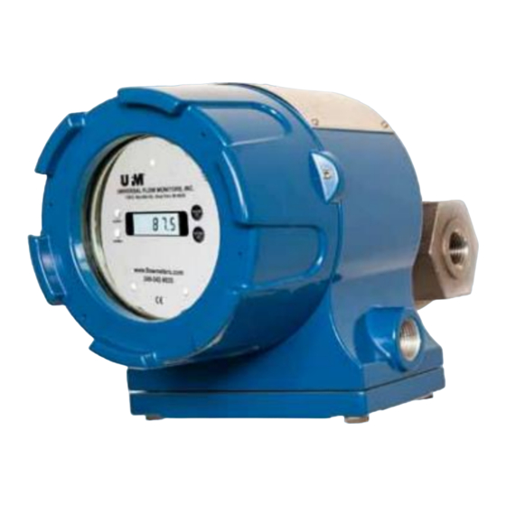
Vane/Piston EXL/H
with Explosion Proof Enclosure
Installation and Operation Manual
Flowmeter Series:
PI, MN, MM, MH
Equipped with E control boxes
including 4-20 mA transmitter
Universal Flow Monitors, Inc.
1755 E. Nine Mile Road • P.O. Box 249 • Hazel Park, MI 48030
Tel: 248-542-9635 • Fax: 248-398-4274
www.flowmeters.com • E-mail: ufm@flowmeters.com
Website:
http://www.flowmeters.com
EX-MANUAL-032321
Advertisement
Table of Contents


Need help?
Do you have a question about the PI Series and is the answer not in the manual?
Questions and answers