Advertisement
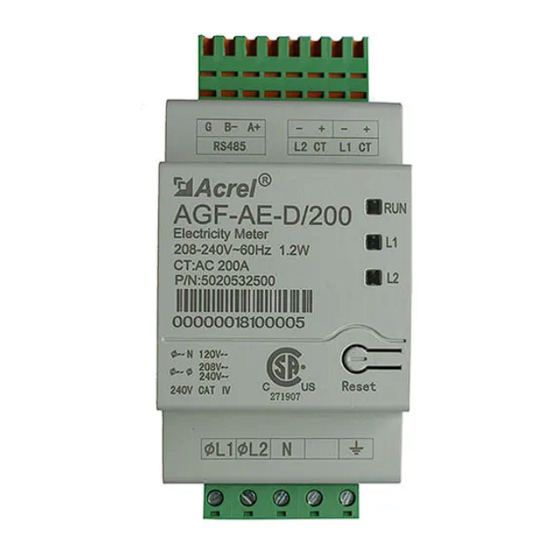
Interface:
Specification:
General
Model No.
Rated Voltage-Line to N
Rated Voltage-Line to Line
Extended Voltage Range
AC Frequency
Grids Supported
Power Consumption
CT Rated RMS Current
Number of Supplied CTs
Standard Compliance
Safety
Installation Specifications
Meter Dimensions(H*W*D)
CT Dimension (H×W×D)
Meter Weight
Operating Temp. Range
Relative Humidity
Meter Mounting Type
External Meter Wiring Instruction
COMM Port
AC Power Input
CT Input
AGF-AE-D/200
120V
240V
88%~110%
60Hz
L1/L2/N/PE
1.2W
200A
2
UL1741
2.13*3.45*2.05in (54.1*87.8*52mm)
2.76*2.15*1.54in(70.5*54.5*39mm)
0.44lbs (0.2kg)
-30~55℃
5 - 90%
DIN-Rail 35mm
Status Indicator
Advertisement
Table of Contents

Related Manuals for Acrel AGF-AE-D/200


Summary of Contents for Acrel AGF-AE-D/200
- Page 1 External Meter Wiring Instruction Interface: CT Input COMM Port Status Indicator AC Power Input Specification: General Model No. AGF-AE-D/200 Rated Voltage-Line to N 120V Rated Voltage-Line to Line 240V Extended Voltage Range 88%~110% AC Frequency 60Hz Grids Supported L1/L2/N/PE Power Consumption 1.2W...
- Page 2 Accessory List: Connector Installation and Cable Connection: Refer to Meter Wire Diagram attached on the 3rd page for more details. CAUTION: Make sure the power is cut off before installation. CAUTION: The direction of CT must be the same as shown on the Wire Diagram. 1.
- Page 4 Terminal Disassembling Instruction: Step One Step Two Step Three Status Indicator Instruction: Indicator Description Troubleshooting Blinking Green: Running normally Solid Red>3s: Internal fault Replace the Meter Blinking Yellow: No communication Solid Green>3s: No Current Blinking Green: Positive power Blinking Red: Negative power Blinking Red &...
Need help?
Do you have a question about the AGF-AE-D/200 and is the answer not in the manual?
Questions and answers