Table of Contents
Advertisement
Quick Links
Advertisement
Table of Contents

Subscribe to Our Youtube Channel
Related Manuals for Amit IOG851-WT041


Summary of Contents for Amit IOG851-WT041
- Page 1 4G PoE IIoT Gateway IOG851-WT041 User Manual...
-
Page 2: Table Of Contents
4G PoE IIoT Gateway Chapter 1 Introduction ............................7 1.1 Introduction ............................. 7 1.2 Contents List ............................. 8 1.2.1 Package Contents ........................... 8 1.2.2 Optional Accessories ........................9 1.3 Hardware Configuration ......................... 10 1.4 LED Indication ............................12 1.5 Installation & Maintenance Notice ......................13 1.5.1 SYSTEM REQUIREMENTS ...................... - Page 3 4G PoE IIoT Gateway 2.2.3 DHCP Server ..........................74 2.2.4 Power over Ethernet ........................82 2.3 WiFi ................................ 85 2.3.1 WiFi Configuration ........................86 2.3.2 Wireless Client List ........................99 2.3.3 Advanced Configuration ......................101 2.4 IPv6 ............................... 103 2.4.1 IPv6 Configuration ........................103 2.5 Port Forwarding ...........................
- Page 4 4G PoE IIoT Gateway 3.5.1 Configuration..........................161 3.5.2 My Certificate ..........................164 3.5.3 Trusted Certificate ........................171 3.5.4 Issue Certificate ......................... 178 Chapter 4 Field Communication ........................181 4.1 Bus & Protocol ............................181 4.1.1 Port Configuration ........................181 4.1.2 Virtual COM ..........................183 4.1.3 Modbus .............................
- Page 5 4G PoE IIoT Gateway 6.1.1 Command Script ........................279 6.1.2 TR-069 ............................283 6.1.3 SNMP ............................288 6.1.4 Telnet & SSH ..........................299 6.2 System Operation ..........................303 6.2.1 Password & MMI ........................303 6.2.2 System Information ........................307 6.2.3 System Time ..........................308 6.2.4 System Log ..........................
- Page 6 4G PoE IIoT Gateway 8.1.1 Device Dashboard ........................364 8.2 Basic Network ............................366 8.2.1 WAN & Uplink Status ........................ 366 8.2.2 LAN & VLAN Status ........................370 8.2.3 WiFi Status ..........................371 8.2.4 DDNS Status ..........................374 8.3 Security ..............................375 8.3.1 VPN Status ..........................
-
Page 7: Chapter 1 Introduction
1.1 Introduction Congratulations on your purchase of this outstanding product: 4G PoE IIoT Gateway. For M2M (Machine-to- Machine) applications, AMIT 4G PoE IIoT Gateway is absolutely the right choice. With a built-in world-class 4G LTE module, you just need to insert SIM card from local mobile carrier to get to Internet. -
Page 8: Contents List
4G PoE IIoT Gateway 1.2 Contents List 1.2.1 Package Contents #Standard Package Items Description Contents Quantity IOG851-WT041 1pcs 4G PoE IIoT Gateway 8 pin Terminal Block 1pcs 4 pin Terminal Block 1pcs RJ45 Cable 1pcs DIN-Rail Bracket 1pcs... -
Page 9: Optional Accessories
#Optional parts (these parts are sold separately) Items Description Contents Comments INPUT: 100-240VAC/1.4A Power Supply 50/60Hz (SDR-120-48) OUTPUT: 48V/2.5A Total Watt: 120W INPUT: 100-240VAC/2.6A Power Supply 50/60Hz (SDR-240-48) OUTPUT: 48V/5A Total Watt: 240W These parts are sold separately. If necessary, please contact us sales@amit.com.tw... -
Page 10: Hardware Configuration
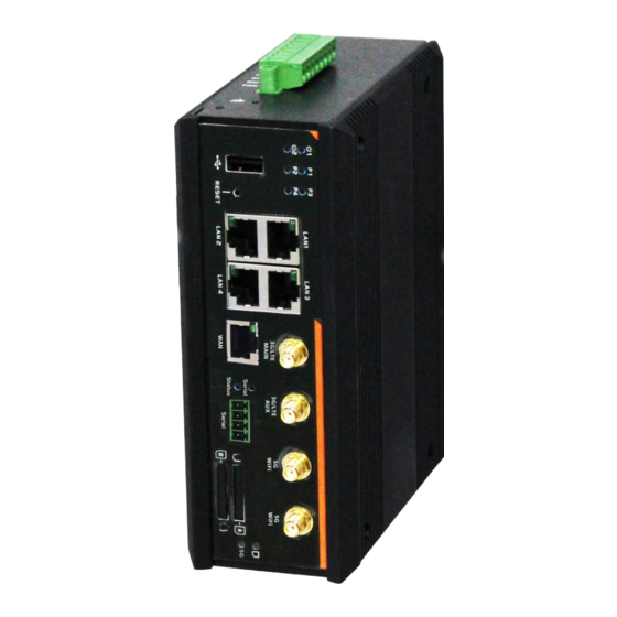
4G PoE IIoT Gateway 1.3 Hardware Configuration Front View 3G/4G WiFi Indicators Antenna Antenna Reset Serial SIM B SIM A Button Port Port Slot Slot Auto MDI/MDIX RJ45 Ports Auto MDI/MDIX RJ45 Port 4x GE LAN (with 802.3at PSE) 1x GE Configurable WAN ※Reset Button The RESET button provides user with a quick and easy way to resort the default setting. - Page 11 4G PoE IIoT Gateway Left View DI/DO DC Power Earth Ground Terminal Block Terminal Block Screw...
-
Page 12: Led Indication
4G PoE IIoT Gateway 1.4 LED Indication LED Color LED Icon Indication Description Steady ON: Device is powered on by power source 1 Power Source 1 Blue Power Source 2 Blue Steady ON: Device is powered on by power source 2 Steady ON: Supply PoE Power through Ethernet Port. -
Page 13: Installation & Maintenance Notice
4G PoE IIoT Gateway 1.5 Installation & Maintenance Notice 1.5.1 SYSTEM REQUIREMENTS An gigabit Ethernet RJ45 cable • 3G/4G cellular service subscription • Network Requirements IEEE 802.11 a/b/g/n/ac wireless clients • 10/100/1000 Ethernet adapter on PC • Computer with the following: Windows®, Macintosh, or Linux-based operating •... - Page 14 4G PoE IIoT Gateway Federal Communication Commission Interference Statement This device complies with Part 15 of the FCC Rules. Operation is subject to the following two conditions: (1) This device may not cause harmful interference, and (2) this device must accept any interference received, including interference that may cause undesired operation.
-
Page 15: Hot Surface Caution
4G PoE IIoT Gateway 1.5.3 HOT SURFACE CAUTION CAUTION: The surface temperature for the metallic enclosure can be very high! Especially after operating for a long time, installed at a closed cabinet without air conditioning support, or in a high ambient temperature space. -
Page 16: Product Information For Ce Red Requirements
4G PoE IIoT Gateway 1.5.4 Product Information for CE RED Requirements The following product information is required to be presented in product User Manual for latest CE RED requirements. (1) Frequency Band & Maximum Power 1.a Frequency Band for Cellular Connection (for ME3630 E1C version) Band number Operating Frequency Max output power... - Page 17 4G PoE IIoT Gateway Downlink: 791-821 MHz LTE FDD BAND 38 Uplink: 2570-2620 MHz 21.7 dBm Downlink: 2570-2620 MHz LTE FDD BAND 40 Uplink: 2300-2400 MHz 21.5 dBm Downlink: 2300-2400 MHz WCDMA BAND 1 Uplink: 1920-1980 MHz Downlink: 2110-2170 MHz 23.3 dBm WCDMA BAND 8 Uplink:...
- Page 18 Ensure the unit is fixed tightly to reduce the likelyhood of injury due to exposure to mechanical hazards if dropped. (7) Manufacture Information Manufacture Name: AMIT Wireless Inc. Manufacture Address: No. 28, Lane 31, Sec. 1, Huandong Rd., Sinshih Dist., Tainan 74146, Taiwan (R.O.C.)
-
Page 19: Hardware Installation
4G PoE IIoT Gateway 1.6 Hardware Installation This chapter describes how to install and configure the hardware 1.6.1 Mount the Unit The IOG851-W series product can be mounted on a wall, horizontal plane, or DIN Rail in a cabinet with the mounting accessories (brackets or DIN-rail kit). -
Page 20: Install The External Rf Cable And Antenna
4G PoE IIoT Gateway 1.6.3 Install the External RF Cable and Antenna As illustrated in Section 1.3, there are several SMA antenna Jacks for you to install the required RF cables and antennas for the RF signal transmission and receiving. You have to purchase required RF cables and antennas separately for a specific project or installation site to get excellent RF performance. -
Page 21: Connecting Di/Do Devices
4G PoE IIoT Gateway 1.6.4 Connecting DI/DO Devices There are one DI and one DO ports together with power terminal block. Please refer to following specification to connect DI and DO devices. Mode Specification Trigger Voltage (high) Logic level 1: 5V~30V Digital Input Normal Voltage (low) Logic level 0: 0V~2V... -
Page 22: Connecting Serial Devices
4G PoE IIoT Gateway 1.6.5 Connecting Serial Devices The IOG851-W series products provide 4-pin Terminal Block serial port for connecting to your serial device. Connect the serial device to the terminal block with the right pin assignments of RS-232/485 are shown as below. -
Page 23: Connecting Power
4G PoE IIoT Gateway 1.6.6 Connecting Power IOG851-W series product can be powered by connecting one or two power sources to the terminal block. It supports dual 24 to 56V DC power inputs. Following picture indicates the power terminal block pin assignments. - Page 24 4G PoE IIoT Gateway The terminal pin number assignment as below Please connect the live line, neutral line and earth line to the corresponding location. DC Power Terminal Block Installation The Power Supply unit may consist of one set or two sets of DC power output contacts. You can connect the DC power supply and the terminal block power pins, as shown below, of the gateway with a power cable.
- Page 25 4G PoE IIoT Gateway Finally, connect the power plug of the power supply cable to an outlet, then the power supply units will turn on and provide DC power to the connected device.
-
Page 26: Connecting To The Network Or A Host
4G PoE IIoT Gateway 1.6.8 Connecting to the Network or a Host The IOG851-W series provides RJ45 ports to connect 10/100/1000Mbps Ethernet. It can auto detect the transmission speed on the network and configure itself automatically. Connect one Ethernet cable to the RJ45 port (LAN) of the device and plug another end of the Ethernet cable into your computer’s network port. -
Page 27: Chapter 2 Basic Network
4G PoE IIoT Gateway Chapter 2 Basic Network 2.1 WAN & Uplink The gateway provides multiple WAN interfaces to let all client hosts in Intranet of the gateway access the Internet via ISP. But ISPs in the world apply various connection protocols to let gateways or user's devices dial in ISPs and then link to the Internet via different kinds of transmit media. -
Page 28: Physical Interface
4G PoE IIoT Gateway 2.1.1 Physical Interface M2M gateways are usually equipped with various WAN interfacess to support different WAN connection scenario for requirement. You can configure the WAN interface one by one to get proper internet connection setup. Refer to the product specification for the available WAN interfaces in the product you purchased. The first step to configure one WAN interface is to specify which kind of connection media to be used for the WAN connection, as shown in "Physical Interface"... - Page 29 4G PoE IIoT Gateway Operation Mode: There are three option items “Always on”, “Failover”, and “Disable” for the operation mode setting. Always on: Set this WAN interface to be active all the time. When two or more WAN are established at "Always on"...
- Page 30 4G PoE IIoT Gateway The purpose is to shorten the switch time during failover process. So, when primary connection is disconnected, failover interface will take over the data transfer mission instantly by only changing routing path to the failover interface. The dialing-up time of failover connection is saved since it has been connected beforehand.
- Page 31 4G PoE IIoT Gateway Physical Interface Setting Go to Basic Network > WAN > Physical Interface tab. The Physical Interface allows user to setup the physical WAN interface and to adjust WAN’s behavior. Note: Numbers of available WAN Interfaces can be different for the purchased gateway. When Edit button is applied, an Interface Configuration screen will appear.
- Page 32 4G PoE IIoT Gateway secondary WAN link failed. Then select the primary or the existed secondary WAN interface to switch Failover from. (Note: for WAN-1, only Always on option is available.) Check Enable box to enter tag value provided by your ISP. Otherwise uncheck the box.
-
Page 33: Internet Setup
4G PoE IIoT Gateway 2.1.2 Internet Setup After specifying the physical interface for each WAN connection, administrator must configure their connection profile to meet the dial in process of ISP, so that all client hosts in the Intranet of the gateway can access the Internet. - Page 34 4G PoE IIoT Gateway Internet Connection List - Ethernet WAN WAN Type for Ethernet Interface: Ethernet is the most common WAN and uplink interface for M2M gateways. Usually it is connected with xDSL or cable modem for you to setup the WAN connection. There are various WAN types to connect with ISP. •...
- Page 35 4G PoE IIoT Gateway WAN Type = Dynamic IP When you select it, "Dynamic IP WAN Type Configuration" will appear. Items and setting is explained below Dynamic IP WAN Type Configuration Item Value setting Description Host Name An optional setting Enter the host name provided by your Service Provider.
- Page 36 4G PoE IIoT Gateway Static IP WAN Type Configuration Item Value setting Description WAN IP Address A Must filled setting Enter the WAN IP address given by your Service Provider WAN Subnet Mask A Must filled setting Enter the WAN subnet mask given by your Service Provider WAN Gateway A Must filled setting Enter the WAN gateway IP address given by your Service Provider...
- Page 37 4G PoE IIoT Gateway WAN Type= PPTP When you select it, "PPTP WAN Type Configuration" will appear. Items and setting is explained below PPTP WAN Type Configuration Item Value setting Description Select either Static or Dynamic IP address for PPTP Internet connection. When Static IP Address is selected, you will need to enter the WAN IP ...
- Page 38 4G PoE IIoT Gateway WAN Type= L2TP When you select it, "L2TP WAN Type Configuration" will appear. Items and setting is explained below L2TP WAN Type Configuration Item Value setting Description Select either Static or Dynamic IP address for L2TP Internet connection. When Static IP Address is selected, you will need to enter the WAN IP ...
- Page 39 4G PoE IIoT Gateway Ethernet Connection Common Configuration There are some important parameters to be setup no matter which Ethernet WAN type is selected. You should follow up the rule to configure. Connection Contro Auto-reconnect: This gateway will establish Internet connection automatically once it has been booted up, and try to reconnect once the connection is down.
- Page 40 4G PoE IIoT Gateway Manually: This gateway won’t start to establish WAN connection until you press “Connect” button on web UI. After normal data transferring between LAN and WAN sides, this gateway will disconnect WAN connection if idle time reaches value of Maximum Idle Time.
- Page 41 4G PoE IIoT Gateway Set up “Ethernet Common Configuration” Ethernet WAN Common Configuration Item Value setting Description There are three connection modes. • Auto-reconnect enables the router to always keep the Internet connection on. • Connect-on-demand enables the router to automatically re- establish Internet connection as soon as user attempts to access Connection Control A Must filled setting...
- Page 42 4G PoE IIoT Gateway Network Monitoring Configuration Item Value setting Description 1. An optional setting Check the Enable box to activate the network monitoring function. Network Monitoring 2. Box is checked by Configuration default Choose either DNS Query or ICMP Checking to detect WAN link. 1.
- Page 43 4G PoE IIoT Gateway Value Range: 1 ~ 10 times. Target1 specifies the first target of sending DNS query/ICMP request. 1. An Optional filled DNS1: set the primary DNS to be the target. setting Target 1 DNS2: set the secondary DNS to be the target. 2.
- Page 44 4G PoE IIoT Gateway Internet Connection – 3G/4G WAN Preferred SIM Card – Dual SIM Fail Over For 3G/4G embedded device, one embedded cellular module can create only one WAN interface. This device has featured by using dual SIM cards for one module with special fail-over mechanism. It is called Dual SIM Failover.
- Page 45 4G PoE IIoT Gateway SIM-A/SIM-B only: When “SIM-A Only” or “SIM-B Only” is used, the specified SIM slot card is the only one to be used for negotiation parameters between gateway device and cellular ISP. SIM-A / SIM-B first without enable Failback By default, “SIM-A First”...
- Page 46 4G PoE IIoT Gateway Configure 3G/4G WAN Setting When Edit button is applied, Internet Connection Configuration, and 3G/4G WAN Configuration screens will appear. 3G/4G Connection Configuration Item Value setting Description 1. A Must filled setting From the dropdown box, select Internet connection method for 3G/4G WAN Type 2.
- Page 47 4G PoE IIoT Gateway Note: Keep it unchecked unless your cellular ISP asked the connected gateway to enable the Auto Flight Mode. Click the Policy Setting button to define the SIM Switch policy or browse SIM Switch Policy the current policy settings. Configure SIM-A / SIM-B Card Here you can set configurations for the cellular connection according to your situation or requirement.
- Page 48 4G PoE IIoT Gateway Connection with SIM-A/-B Card Item Value setting Description Select Auto to register a network automatically, regardless of the network type. Select 2G Only to register the 2G network only. 1. A Must filled setting Select 2G Prefer to register the 2G network first if it is available. Network Type 2.
- Page 49 4G PoE IIoT Gateway configurations on your own, you can switch to Static IP mode and fill in all parameters that required, such as IP address, subnet mask and gateway. Note: IP Subnet Mask is a must filled setting, and make sure you have the right configuration.
- Page 50 4G PoE IIoT Gateway listed 2. String format : any text String format : any text Enter the APN you want to use to establish the connection. 1. A Must filled setting Specify the IP type of the network serveice provided by your 3G/4G IP Type 2.
- Page 51 4G PoE IIoT Gateway Basic Network > WAN & Uplink tab for details. Note: If the WAN interface serves as the primary one for another WAN interface in Failover role( and vice versa), the Connection Control parameter will not be available on both WANs as the system must set it to “Auto-reconnect”...
- Page 52 4G PoE IIoT Gateway Network Monitoring Configuration Item Value setting Description 1. An optional setting Check the Enable box to activate the network monitoring function. Network Monitoring 2. Box is checked by Configuration default Choose either DNS Query or ICMP Checking to detect WAN link. 1.
-
Page 53: Load Balance
4G PoE IIoT Gateway 2.1.3 Load Balance When there are multiple WAN interfaces, and when the bandwidth of one WAN connection is not enough for the traffic loads from the Intranet to the Internet, the WAN load balance function can be considered to enlarge the total WAN bandwidth. - Page 54 4G PoE IIoT Gateway By Specific Weight When you select "By Specific Weight", you need to set up ratio of WAN-1/WAN-2 to decide sessions sent ratio. Total ratio should be 100%. Ratio is usually defined based on practical WAN speed of environment.
- Page 55 4G PoE IIoT Gateway Load Balance Setting Go to Basic Network > WAN & Uplink > Load Balance Tab. The Load Balance function is used to manage balance bandwidth usage among multiple WAN connections When you choose "By Smart Weight" strategy, system will operate load balance function automatically based on the embedded Smart Weight algorithm.
- Page 56 4G PoE IIoT Gateway Weight Definition Item Value setting Description WAN ID The Identifier for each available WAN interface.. Enter the weight ratio for each WAN interface. 1. A Must filled setting Initially, the bandwidth ratio of each WAN is set by default. Weight 2.
- Page 57 4G PoE IIoT Gateway is : xxx.xxx.xxx.xxx/xx e.g. 192.168.123.0/24. IP Range: Specify the IP Range for the traffics come from the IPs Single IP: Specify a unique IP Address for the traffics come from the IP. Input format is : xxx.xxx.xxx.xxx e.g. 192.168.123.101. There are five options can be selected : Any: No specific destination IP is provided.
-
Page 58: Lan & Vlan
4G PoE IIoT Gateway 2.2 LAN & VLAN This section provides the configuration of LAN and VLAN. VLAN is an optional feature, and it depends on the product specification of the purchased gateway. 2.2.1 Ethernet LAN The Local Area Network (LAN) can be used to share data or files among computers attached to a network. - Page 59 4G PoE IIoT Gateway by default The default subnet mask is 255.255.255.0 (/24), and it means maximum 254 IP addresses are allowed in this subnet. However, one of them is occupied by LAN IP address of this gateway, so there are maximum 253 clients allowed in LAN network.
- Page 60 4G PoE IIoT Gateway network. Value Range: 255.0.0.0 (/8) ~ 255.255.255.255 (/32). Save Click the Save button to save the configuration...
-
Page 61: Vlan
4G PoE IIoT Gateway 2.2.2 VLAN VLAN (Virtual LAN) is a logical network under a certain switch or router device to group client hosts with a specific VLAN ID. This gateway supports both Port-based VLAN and Tag-based VLAN. These functions allow you to divide local network into different “virtual LANs”. - Page 62 4G PoE IIoT Gateway Staff) with NAT mode and DHCP-2 server equipped. At last, administrator also configure Data Center segment with VLAN ID 1. The VLAN group includes Port-1 with NAT mode to WAN interface as shown in following diagram. Above is the general case for 3 Ethernet LAN ports in the gateway.
- Page 63 4G PoE IIoT Gateway For example, in a company, administrator schemes out 3 network segments, Lab, Meeting Rooms, and Office. In a Security VPN Gateway, administrator can configure Office segment with VLAN ID 12. The VLAN group is equipped with DHCP-3 server to construct a 192.168.12.x subnet. He also configure Meeting Rooms segment with VLAN ID 11.
- Page 64 4G PoE IIoT Gateway VLAN Groups Access Control Administrator can specify the Internet access permission for all VLAN groups. He can also configure which VLAN groups are allowed to communicate with each other. VLAN Group Internet Access Administrator can specify members of one VLAN group to be able to access Internet or not. Following is an example that VLAN groups of VID is 2 and 3 can access Internet but the one with VID is 1 cannot access Internet.
- Page 65 4G PoE IIoT Gateway Inter VLAN Group Routing: In Port-based tagging, administrator can specify member hosts of one VLAN group to be able to communicate with the ones of another VLAN group or not. This is a communication pair, and one VLAN group can join many communication pairs.
- Page 66 4G PoE IIoT Gateway VLAN Setting Go to Basic Network > LAN & VLAN > VLAN Tab. The VLAN function allows you to divide local network into different virtual LANs. There are Port-based and Tag-based VLAN types. Select one that applies. Configuration Item Value setting...
- Page 67 4G PoE IIoT Gateway Port-based VLAN - Configuration Port-based VLAN Configuration (part-I) Item Value setting Description 1. A Must filled setting Define the Name of this rule. It has a default text and cannot be modified. Name 2. String format: already have default texts VLAN ID A Must filled setting...
- Page 68 4G PoE IIoT Gateway Port-based VLAN Configuration (part-II) Item Value setting Description WAN & WAN All WANs is selected by Select which WAN or All WANs that allow accessing Internet. VID to Join default. Note: If Bridge mode is selected, you need to select a WAN and enter a VID. LAN IP Assign an IP Address for the DHCP Server that the rule used, this IP address is a A Must filled setting...
- Page 69 4G PoE IIoT Gateway Define a period of time for an IP Address that the DHCP Server leases to a new Lease Time A Must filled setting device. By default, the lease time is 86400 seconds. String format can be any The Domain Name of this DHCP Server.
- Page 70 4G PoE IIoT Gateway Besides, you can add some IP rules in the IP Fixed Mapping Rule List if DHCP Server for the VLAN groups is required. When Add button is applied, Mapping Rule Configuration screen will appear. Mapping Rule Configuration Item Value setting Description...
- Page 71 4G PoE IIoT Gateway Port-based VLAN – Inter VLAN Group Routing Click VLAN Group Routing button, the VLAN Group Internet Access Definition and Inter VLAN Group Routing screen will appear. When Edit button is applied, a screen similar to this will appear. Inter VLAN Group Routing Item Value setting...
- Page 72 4G PoE IIoT Gateway Note: VLAN ID 1 is available always; it is the default VLAN ID of LAN rule. The other VLAN IDs are available only when they are enabled. Click the expected VLAN IDs box to enable the Inter VLAN access function. By default, members in different VLAN IDs can’t access each other.
- Page 73 4G PoE IIoT Gateway If you select New to create a new DHCP server setting for the VLAN group, you have to further specify the following configuration. Tag-based VLAN Configuration (part-II) Item Value setting Description Assign an IP Address for the DHCP Server that the rule used, this IP address is a IP Address A Must filled setting gateway IP.
-
Page 74: Dhcp Server
4G PoE IIoT Gateway 2.2.3 DHCP Server DHCP Server The gateway supports up to 4 DHCP servers to fulfill the DHCP requests from different VLAN groups (please refer to VLAN section for getting more usage details). And there is one default setting for whose LAN IP Address is the same one of gateway LAN interface, with its default Subnet Mask setting as “255.255.255.0”, and its default IP Pool ranges is from “.100”... - Page 75 4G PoE IIoT Gateway Fixed Mapping User can assign fixed IP address to map the specific client MAC address by select them then copy, when targets were already existed in the DHCP Client List, or to add some other Mapping Rules by manually in advance, once the target's MAC address was not ready to connect.
- Page 76 4G PoE IIoT Gateway DHCP Server Setting Go to Basic Network > LAN & VLAN > DHCP Server Tab. The DHCP Server setting allows user to create and customize DHCP Server policies to assign IP Addresses to the devices on the local area network (LAN) Create / Edit DHCP Server Policy The gateway allows you to custom your DHCP Server Policy.
- Page 77 4G PoE IIoT Gateway DHCP Server Configuration Item Value setting Description 1. String format can be any DHCP Server text Enter a DHCP Server name. Enter a name that is easy for you to understand. Name 2. A Must filled setting 1.
- Page 78 4G PoE IIoT Gateway Mapping Rule Configuration Item Value setting Description 1. MAC Address string MAC Address format The MAC Address of this mapping rule. 2. A Must filled setting 1. IPv4 format. IP Address The IP Address of this mapping rule. 2.
- Page 79 4G PoE IIoT Gateway Option Meaning TFTP server name [RFC 2132] [RFC 2132] Default World Wide Web Server [RFC 3679] Create / Edit DHCP Server Options The gateway supports up to a maximum of 99 option settings. When Add/Edit button is applied, DHCP Server Option Configuration screen will appear. DHCP Server Option Configuration Item Value setting...
- Page 80 4G PoE IIoT Gateway Option 66 for tftp; Option 72 for www; Option 144 for url; Each different options has different value types. Single IP Address Single FQDN IP Addresses List, separated by “,” Dropdown list DHCP Single URL Type server option value’s type IP Addresses List, separated by “,”...
- Page 81 4G PoE IIoT Gateway DHCP Relay Configuration Item Value setting Description 1. String format can be any Enter a DHCP Relay name. Enter a name that is easy for you to understand. Agent Name text Value Range: 1~64 characters. 2. A Must filled setting. 1.
-
Page 82: Power Over Ethernet
4G PoE IIoT Gateway 2.2.4 Power over Ethernet Power over Ethernet (PoE) describes any of several standardized or ad-hoc systems which pass electric power along with data on twisted pair Ethernet cabling. This allows a single cable to provide both data connection and electric power to devices such as wireless access points, IP cameras, and VoIP phones. - Page 83 4G PoE IIoT Gateway Power over Ethernet Setting Go to Basic Network > LAN & VLAN > Power over Ethernet Tab. The Power over Ethernet setting allows administrator to control PoE related function, such as Power Budget, Port Power Limit, etc… Define Power Budget Power Configuration Item...
- Page 84 4G PoE IIoT Gateway Low Priority PD Highest by default Specify the Port Priority. It can be Highest, High, or Low. Knockoff Whenever there is a shortage of total power budget, the port with lowest priority will be disabled automatically to provide required power to the ports with higher priority.
-
Page 85: Wifi
4G PoE IIoT Gateway 2.3 WiFi The gateway provides WiFi interface for mobile devices or BYOD devices to connect for Internet/Intranet accessing. WiFi function is usually modulized design in a gateway, and there can be single or dual modules within a gateway. The WiFi system in the gateway complies with IEEE 802.11ac/11n/11g/11b standard in 2.4GHz or 5GHz single band or 2.4G/5GHz concurrent dual bands of operation. -
Page 86: Wifi Configuration
4G PoE IIoT Gateway 2.3.1 WiFi Configuration Due to optional module(s) and frequency band, you need to setup module one by one. For each module, you need to specify the operation mode, and then setup the virtual APs for wireless access. Hereunder are the scenarios for each wireless operation mode, you can get how it works, and what is the difference among them. - Page 87 4G PoE IIoT Gateway WDS Only Mode WDS (Wireless Distributed System) Only mode drives a WiFi gateway to be a bridge for its wired Intranet and a repeater to extend distance. You can use multiple WiFi gateways as a WiFi repeater chain with all gateways setup as "WDS Only"...
- Page 88 4G PoE IIoT Gateway Multiple VAPs VAP (Virtual Access Point) is function to partition wireless network into multiple broadcast domains. It can simulate multiple APs in one physical AP. This wireless gateway supports up to 8 VAPs. For each VAP, you need to setup SSID, authentication and encryption to control Wi-Fi client access.
- Page 89 4G PoE IIoT Gateway WiFi Configuration Setting The WiFi configuration allows user to configure 2.4GHz or 5GHz WiFi settings. Go to Basic Network > WiFi > WiFi Module One Tab. If the gateway is equipped with two WiFi modules, there will be another WiFi Module Two.
- Page 90 4G PoE IIoT Gateway By Less Interference The channel will be selected according to interference. (The lower, the better). Specify the preferred WiFi System. The dropdown list of WiFi system is based on IEEE 802.11 standard. WiFi System A Must filled setting ...
- Page 91 4G PoE IIoT Gateway by clicking the Edit button. Click Add / Edit button in the VAP List screen to create or edit the settings for a VAP. A VAP Configuration screen will appear. For VAP 1: For others: VAP Configuration Item Value setting Description...
- Page 92 4G PoE IIoT Gateway by default. station. The box is unchecked by default. It means no special limitation on the number of connected STAs. For security, there are several authentication methods supported. Client stations should provide the key when associate with this device. When Open is selected The check box named 802.1x shows up next to the dropdown list.
- Page 93 4G PoE IIoT Gateway TKIP TKIP was proposed instead of WEP without upgrading hardware. Enter a Pre- shared Key for it. The length of key is from 8 to 63 characters. The newest encryption system in WiFi, it also designed for the fast 802.11n high bitrates schemes.
- Page 94 4G PoE IIoT Gateway WDS Only Mode For the WDS Only mode, the device only bridges the connected wired clients to another WDS-enabled WiFi device which the device associated with. That is, it also means the no wireless clients stat can connect to this device while WDS Only Mode is selected.
- Page 95 4G PoE IIoT Gateway Under WDS Only mode, only VAP1 is available for further specifying the required authentication and Encryption settings. Click Edit button in the VAP List screen and a VAP Configuration screen will appear for you to configure the required settings For the detail description about VAP configuration, please refer to the description stated in AP-Router section.
- Page 96 4G PoE IIoT Gateway WDS Hybrid Mode For the WDS Hybrid mode, the device bridges all the wired LAN and WLAN clients to another WDS or WDS hybrid enabled WiFi devices which the device associated with. WDS Hybrid Mode Item Value setting Description Check the Enable box to activate this function.
- Page 97 4G PoE IIoT Gateway differs from devices. So, you can connected to the VAP1 (SSID: Staff_2.4G) with the provided key. However, it is strongly recommanded that you have to change the security key to a easy-to-remember one by clicking the Edit button. Under WDS Hybrid mode, the VAP function is available and you can further specifying the required VAP settings for connecting with wireless client devices.
- Page 98 4G PoE IIoT Gateway For others: For the detail description about VAP configuration, please refer to the description stated in AP-Router section.
-
Page 99: Wireless Client List
4G PoE IIoT Gateway 2.3.2 Wireless Client List The Wireless Client List page shows the information of wireless clients which are associated with this device. Go to Basic Network > WiFi > Wireless Client List Tab. Select Target WiFi Target Configuration Item Value setting Description... - Page 100 4G PoE IIoT Gateway RSSI0, RSSI1 It shows the RX sensitivity (RSSI) value for each radio path. Signal The signal strength between client and this device. Interface It shows the VAP ID that the client associated with. Refresh Click the Refresh button to update the Client List immediately.
-
Page 101: Advanced Configuration
4G PoE IIoT Gateway 2.3.3 Advanced Configuration This device provides advanced wireless configuration for professional user to optimize the wireless performance under the specific installation environment. Please note that if you are not familiar with the WiFi technology, just leave the advanced configuration with its default values, or the connectivity and performance may get worse with improper settings. - Page 102 4G PoE IIoT Gateway Advanced Configuration Item Value setting Description The default setting is It limits the available radio channel of this device. Regulatory Domain according to where The permissible channels depend on the Regulatory Domain. the product sale to It shows the time interval between each beacon packet broadcasted.
-
Page 103: Ipv6
4G PoE IIoT Gateway 2.4 IPv6 The growth of the Internet has created a need for more addresses than are possible with IPv4. IPv6 (Internet Protocol version 6) is a version of the Internet Protocol (IP) intended to succeed IPv4, which is the protocol currently used to direct almost all Internet traffic. - Page 104 4G PoE IIoT Gateway IPv6 WAN Connection Type Static IPv6 Static IPv6 does the same function as static IPv4. The static IPv6 provides manual setting of IPv6 address, IPv6 default gateway address, and IPv6 DNS. Above diagram depicts the IPv6 IP addressing, type in the information provided by your ISP to setup the IPv6 network.
- Page 105 4G PoE IIoT Gateway PPPoEv6 PPPoEv6 in IPv6 does the same function as PPPoE in IPv4. The PPPoEv6 server provides configuration parameters based on PPPoEv6 client request. When PPPoEv6 server gets client request and successfully authenticates it, the server sends IP address, DNS server addresses and other required parameters to automatically configure the client.
- Page 106 4G PoE IIoT Gateway IPv6 Configuration Setting Go to Basic Network > IPv6 > Configuration Tab. The IPv6 Configuration setting allows user to set the IPv6 connection type to access the IPv6 network. IPv6 Configuration Item Value setting Description The box is unchecked IPv6 Check the Enable box to activate the IPv6 function.
- Page 107 4G PoE IIoT Gateway Length Default Gateway A Must filled setting Enter the WAN Default Gateway IPv6 address. Primary DNS Enter the WAN primary DNS Server. An optional setting Secondary DNS An optional setting Enter the WAN secondary DNS Server. The box is unchecked MLD Snooping Enable/Disable the MLD Snooping function...
- Page 108 4G PoE IIoT Gateway DHCPv6 WAN Type Configuration DHCPv6 WAN Type Configuration Item Value setting Description The option [From Select the [Specific DNS] option to active Primary DNS and Secondary DNS. Then Server] is selected by fill the DNS information. default Can not modified by Primary DNS...
- Page 109 4G PoE IIoT Gateway PPPoEv6 WAN Type Configuration PPPoEv6 WAN Type Configuration Item Value setting Description Enter the Account for setting up PPPoEv6 connection. If you want more Account A Must filled setting information, please contact your ISP. Value Range: 0 ~ 45 characters. Enter the Password for setting up PPPoEv6 connection.
- Page 110 4G PoE IIoT Gateway Then go to Address Auto-configuration (summary) for setting LAN environment. If above setting is configured, click the save button to save the configuration and click reboot button to reboot the router. Address Auto-configuration Address Auto-configuration Item Value setting Description The box is unchecked...
-
Page 111: Port Forwarding
4G PoE IIoT Gateway 2.5 Port Forwarding Network address translation (NAT) is a methodology of remapping one IP address space into another by modifying network address information in Internet Protocol (IP) datagram packet headers while they are in transit across a traffic routing device. The technique was originally used for ease of rerouting traffic in IP networks without renumbering every host. -
Page 112: Configuration
4G PoE IIoT Gateway 2.5.1 Configuration NAT Loopback This feature allows you to access the WAN global IP address from your inside NAT local network. It is useful when you run a server inside your network. For example, if you set a mail server at LAN side, your local devices can access this mail server through gateway’s global IP address when enable NAT loopback feature. -
Page 113: Virtual Server & Virtual Computer
4G PoE IIoT Gateway 2.5.2 Virtual Server & Virtual Computer There are some important Pot Forwarding functions implemented within the gateway, including "Virtual Server", "NAT loopback" and "Virtual Computer". It is necessary for cooperate staffs who travel outside and want to access various servers behind office gateway. - Page 114 4G PoE IIoT Gateway Virtual Server & NAT Loopback "Virtual Server" allows you to access servers with the global IP address or FQDN of the gateway as if they are servers existed in the Internet. But in fact, these servers are located in the Intranet and are physically behind the gateway.
- Page 115 4G PoE IIoT Gateway Virtual Server & Virtual Computer Setting Go to Basic Network > Port Forwarding > Virtual Server & Virtual Computer tab. Enable Virtual Server and Virtual Computer Configuration Item Value setting Description The box is unchecked by Virtual Server Check the Enable box to activate this port forwarding function default...
- Page 116 4G PoE IIoT Gateway Virtual Server Rule Configuration Item Value setting Description Define the selected interface to be the packet-entering interface of the gateway. If the packets to be filtered are coming from WAN-x then select WAN-x for this 1. A Must filled setting field.
- Page 117 4G PoE IIoT Gateway When “UDP” is selected It means the option “Protocol” of packet filter rule is UDP. Public Port selected a predefined port from Well-known Service, and Private Port is the same with Public Port number. Public Port is selected Single Port and specify a port number, and Private Port can be set a Single Port number.
- Page 118 4G PoE IIoT Gateway Create / Edit Virtual Computer The gateway allows you to custom your Virtual Computer rules. It supports up to a maximum of 20 rule-based Virtual Computer sets. When Add button is applied, Virtual Computer Rule Configuration screen will appear. Virtual Computer Rule Configuration Item Value setting...
-
Page 119: Dmz & Pass Through
4G PoE IIoT Gateway 2.5.3 DMZ & Pass Through DMZ (De Militarized Zone) Host is a host that is exposed to the Internet cyberspace but still within the protection of firewall by gateway device. So, the function allows a computer to execute 2-way communication for Internet games, Video conferencing, Internet telephony and other special applications. - Page 120 4G PoE IIoT Gateway VPN Pass through Scenario Since VPN traffic is different from that of TCP or UDP connection, it will be blocked by NAT gateway. To support the pass through function for the VPN connections initiating from VPN clients behind NAT gateway, the gateway must implement some kind of VPN pass through function for such application.
- Page 121 4G PoE IIoT Gateway Note: The available check boxes (WAN-1 ~ WAN-4) depend on the number of WAN interfaces for the product. Pass Through Enable The boxes are checked by Check the box to enable the pass through function for the IPSec, PPTP, and default L2TP.
-
Page 122: Special Ap & Alg (Not Supported)
4G PoE IIoT Gateway 2.5.4 Special AP & ALG (not supported) Not supported feature for the purchased product, leave it as blank. -
Page 123: Ip Translation
4G PoE IIoT Gateway 2.5.5 IP Translation IP Translation is slimier to One-to-One NAT. it is a feature where you can configure the gateway with multiple IP addresses issued by your Internet Service Provider (ISP) and map them to individual intranet devices with specific IP addresses. - Page 124 4G PoE IIoT Gateway IP Translation Setting Go to Basic Network > Port Forwarding > IP Translation tab. Enable IP Translation Configuration Item Value setting Description IP Translation The box is unchecked by Check the Enable box to activate the IP translation function default Save Click the Save button to save the settings.
- Page 125 4G PoE IIoT Gateway selected by default. limited with proper subnet setting. Mapping 1. A Must filled setting Specify the expected real target IP / Domain Name that will be used to Destination 2.IP is selected by default. replace the original one that is issued by the hosts behind the NAT gateway. IP/Domain Name Mask 1.
-
Page 126: Routing
4G PoE IIoT Gateway 2.6 Routing If you have more than one router and subnet, you will need to enable routing function to allow packets to find proper routing path and allow different subnets to communicate with each other. Routing is the process of selecting best paths in a network. -
Page 127: Static Routing
4G PoE IIoT Gateway 2.6.1 Static Routing "Static Routing" function lets you define the routing paths for some dedicated hosts/servers or subnets to store in the routing table of the gateway. The gateway routes incoming packets to different peer gateways based on the routing table. - Page 128 4G PoE IIoT Gateway Static Routing Setting Go to Basic Network > Routing > Static Routing Tab. There are three configuration windows for static routing feature, including "Configuration", "Static Routing Rule List" and "Static Routing Rule Configuration" windows. "Configuration" window lets you activate the global static routing feature.
- Page 129 4G PoE IIoT Gateway of each static routing rule can let you modify the rule. IPv4 Static Routing Item Value setting Description 1. IPv4 Format Destination IP Specify the Destination IP of this static routing rule. 2. A Must filled setting 255.255.255.0 (/24) is set by Subnet Mask Specify the Subnet Mask of this static routing rule.
-
Page 130: Dynamic Routing
4G PoE IIoT Gateway 2.6.2 Dynamic Routing Dynamic Routing, also called adaptive routing, describes the capability of a system, through which routes are characterized by their destination, to alter the path that the route takes through the system in response to a change in network conditions. - Page 131 4G PoE IIoT Gateway...
- Page 132 4G PoE IIoT Gateway RIP Scenario The Routing Information Protocol (RIP) is one of the oldest distance-vector routing protocols, which employs the hop count as a routing metric. RIP prevents routing loops by implementing a limit on the number of hops allowed in a path from the source to a destination.
- Page 133 4G PoE IIoT Gateway BGP Scenario Border Gateway Protocol (BGP) is a standard exterior gateway protocol designed to exchange routing and reachability information between autonomous systems (AS) on the Internet. It usually makes routing decisions based on paths, network policies, or rule-sets. Most ISPs use BGP to establish routing between one another (especially for multi-homed).
- Page 134 4G PoE IIoT Gateway Dynamic Routing Setting Go to Basic Network > Routing > Dynamic Routing Tab. The dynamic routing setting allows user to customize RIP, OSPF, and BGP protocol through the router based on their office setting. In the "Dynamic Routing" page, there are several configuration windows for dynamic routing feature. They are the "RIP Configuration"...
- Page 135 4G PoE IIoT Gateway OSPF Configuration Item Value setting Description OSPF Disable is set by default Click Enable box to activate the OSPF protocol. 1. IPv4 Format Router ID The Router ID of this router on OSPF protocol 2. A Must filled setting The Authentication method of this router on OSPF protocol.
- Page 136 4G PoE IIoT Gateway OSPF Area Configuration Item Value setting Description 1. Classless Inter Domain Routing (CIDR) Subnet Area Subnet Mask Notation. (Ex: The Area Subnet of this router on OSPF Area List. 192.168.1.0/24) 2. A Must filled setting 1. IPv4 Format Area ID The Area ID of this router on OSPF Area List.
- Page 137 4G PoE IIoT Gateway BGP Configuration The BGP configuration setting allows user to customize BGP protocol through the router setting. BGP Network Configuration Item Value setting Description The box is unchecked by Check the Enable box to activate the BGP protocol. default 1.
- Page 138 4G PoE IIoT Gateway 2. A Must filled setting the IP address in this field and the selected subnet mask. The box is unchecked by Network Click Enable box to activate this rule. default. Save Click the Save button to save the configuration Create / Edit BGP Neighbor Rules The gateway allows you to custom your BGP Neighbor rules.
-
Page 139: Routing Information
4G PoE IIoT Gateway 2.6.3 Routing Information The routing information allows user to view the routing table and policy routing information. Policy Routing Information is only available when the Load Balance function is enabled and the Load Balance Strategy is By User Policy Go to Basic Network >... -
Page 140: Dns & Ddns
4G PoE IIoT Gateway 2.7 DNS & DDNS How does user access your server if your WAN IP address changes all the time? One way is to register a new domain name, and maintain your own DNS server. Another simpler way is to apply a domain name to a third- party DDNS service provider. - Page 141 4G PoE IIoT Gateway DNS & DDNS Setting Go to Basic Network > DNS & DDNS > Configuration Tab. The DNS & DDNS setting allows user to setup Dynamic DNS feature and DNS redirect rules. Setup Dynamic DNS The gateway allows you to custom your Dynamic DNS settings. DDNS (Dynamic DNS) Configuration Item Value setting...
- Page 142 4G PoE IIoT Gateway Setup DNS Redirect DNS redirect is a special function to redirect certain traffics to a specified host. Administator can manage the internet / intranet traffics that are going to access some restricted DNS and force those traffics to be redirected to a specified host.
- Page 143 4G PoE IIoT Gateway 2. A Must filled setting Value Range: at least 1 character is required; ‘*’ for any. 1. IPv4 format Enter an IP Address as the target for the DNS redirect. 2. A Must filled setting Specify when will the DNS redirect action can be applied. It can be Always, or WAN Block.
-
Page 144: Qos
It is indeed required that an access gateway satisfies the requirements of latency-critical applications, minimum access right guarantee, fair bandwidth usage for same subscribed condition and flexible bandwidth management. AMIT Security Gateway provides a Rule-based QoS to carry out the requirements. - Page 145 4G PoE IIoT Gateway In above diagram, a QoS rule is organized by the premise part and the conclusion part. In the premise part, you must specify the WAN interface, host group, service type in the packets, packet flow direction to be watched and the sharing method of group control or individual control.
- Page 146 4G PoE IIoT Gateway For bandwidth resource, control functions include guaranteeing bandwidth and limiting bandwidth. For priority queue resource, control function is setting priority. For DSCP resource, control function is DSCP marking. The last resource is Connection Sessions; the related control function is limiting connection sessions.
- Page 147 4G PoE IIoT Gateway QoS Rule Example #2 – DifferServ Code Points When the administrator of the gateway wants to convert the code point value, "IP Precedence 4(CS4)", in the packets from some client hosts (IP 10.0.75.196~199) to the code value, "AF Class2(High Drop)", he can use the "Rule-based QoS"...
- Page 148 4G PoE IIoT Gateway QoS Configuration Setting Go to Basic Network > QoS > Configuration tab. In "QoS Configuration" page, there are some configuration windows for QoS function. They are the "Configuration" window, “System Resource Configuration” window, "QoS Rule List" window, and "QoS Rule Configuration"...
- Page 149 4G PoE IIoT Gateway Setup System Resource System Resource Configuration Item Value Setting Description Define the system queues that are available for the QoS settings. 1. A Must filled setting. Type of System The supported type of system queues are Bandwidth Queue and Priority 2.
- Page 150 4G PoE IIoT Gateway Create / Edit QoS Rules After enabled the QoS function and configured the system resources, you have to further specify some QoS rules for provide better service on the interested traffics. The gateway supports up to a maximum of 128 rule- based QoS rule sets.
- Page 151 4G PoE IIoT Gateway Group option become available. Refer to Object Definition > Grouping > Host Grouping. Service 1. A Must filled Specify the service type of traffics that have to be applied with the QoS rule. It setting. can be All, DSCP, TOS, User-defined Service, or Well-known Service. 2.
- Page 152 4G PoE IIoT Gateway setting. selected group. It can be Individual Control or Group Control. 2. Group Control is selected by default. Individual Control: If Individual Control is selected, each host in the group will have his own QoS service resource as specified in the rule. Group Control: If Group Control is selected, all the group hosts share the same QoS service resource.
-
Page 153: Chapter 3 Object Definition
4G PoE IIoT Gateway Chapter 3 Object Definition 3.1 Scheduling Scheduling provides ability of adding/deleting time schedule rules, which can be applied to other functionality. 3.1.1 Scheduling Configuration Go to Object Definition > Scheduling > Configuration tab. Button description Item Value setting Description Click the Add button to configure time schedule rule... - Page 154 4G PoE IIoT Gateway Time Period Definition Item Value Setting Description Week Day Select from menu Select everyday or one of weekday Start Time Time format (hh :mm) Start time in selected weekday End Time Time format (hh :mm) End time in selected weekday Save Click Save to save the settings Undo...
-
Page 155: User (Not Supported)
4G PoE IIoT Gateway 3.2 User (not supported) Not supported feature for the purchased product, leave it as blank. -
Page 156: Grouping
4G PoE IIoT Gateway 3.3 Grouping The Grouping function allows user to make group for some services. 3.3.1 Host Grouping Go to Object Definition > Grouping > Host Grouping tab. The Host Grouping function allows user to make host group for some services, such as QoS, Firewall, and Communication Bus. - Page 157 4G PoE IIoT Gateway When Host Name-based is selected, only host name can be added in Member to Join. Note: The available Group Type can be different for the purchased model. Add the members to the group in this field. You can enter the member information as specified in the Member Type above, Member to Join and press the Join button to add.
-
Page 158: External Server
4G PoE IIoT Gateway 3.4 External Server Go to Object Definition > External Server > External Server tab. The External Server setting allows user to add external server. Create External Server When Add button is applied, External Server Configuration screen will appear. - Page 159 4G PoE IIoT Gateway External Server Configuration Item Value setting Description 1. String format can be Sever Name any text Enter a server name. Enter a name that is easy for you to understand. 2. A Must filled setting Specify the Server Type of the external server, and enter the required settings for the accessing the server.
- Page 160 4G PoE IIoT Gateway TACACS+ Server (A Must filled setting) : When TACACS+ Server is selected, the following settings are also required. Shared Key (String format: any text) Session Timeout (String format: any number) The values must be between 1 and 60. SCEP Server (A Must filled setting) : When SCEP Server is selected, the following settings are also required.
-
Page 161: Certificate
4G PoE IIoT Gateway 3.5 Certificate In cryptography, a public key certificate (also known as a digital certificate or identity certificate) is an electronic document used to prove ownership of a public key. The certificate includes information about the key, information about its owner's identity, and the digital signature of an entity that has verified the certificate's contents are genuine. - Page 162 4G PoE IIoT Gateway Root CA Certificate Configuration Item Value setting Description 1. String format can be any Name text Enter a Root CA Certificate name. It will be a certificate file name 2. A Must filled setting This field is to specify the key attribute of certificate. Key Type to set public-key cryptosystems.
- Page 163 4G PoE IIoT Gateway Setup SCEP SCEP Configuration Item Value setting Description The box is unchecked by SCEP Check the Enable box to activate SCEP function. default When SCEP is activated, check the Enable box to activate this function. Automatically The box is unchecked by re-enroll aging It will be automatically check which certificate is aging.
-
Page 164: My Certificate
4G PoE IIoT Gateway 3.5.2 My Certificate My Certificate includes a Local Certificate List. Local Certificate List shows all generated certificates by the root CA for the gateway. And it also stores the generated Certificate Signing Requests (CSR) which will be signed by other external CAs. - Page 165 HQRootCA Key Type: RSA Key Length: 1024-bits Subject Name Country(C): TW State(ST): Taiwan Location(L): Tainan Organization(O): AMITHQ Organization Unit(OU): HQRD Common Name(CN): HQRootCA E-mail: hqrootca@amit.com.tw Configuration Path [My Certificate]-[Local Certificate Configuration] Name HQCRT Self-signed: ■ Key Type: RSA Key Length: 1024-bits...
- Page 166 [My Certificate]-[Local Certificate Configuration] BranchCRT Self-signed: □ Name Key Type: RSA Key Length: 1024-bits Subject Name Country(C): TW State(ST): Taiwan Location(L): Tainan Organization(O): AMITBranch Organization Unit(OU): BranchRD Common Name(CN): BranchCRT E-mail: branchcrt@amit.com.tw Configuration Path [IPSec]-[Configuration] ■ Enable IPSec Configuration Path [IPSec]-[Tunnel Configuration] Tunnel ■...
- Page 167 4G PoE IIoT Gateway Remote Netmask 255.255.255.0 Remote Gateway 203.95.80.22 Configuration Path [IPSec]-[Authentication] Key Management IKE+X.509 Local Certificate: BranchCRT Remote Certificate: HQCRT Local ID User Name Network-B Remote ID User Name Network-A Configuration Path [IPSec]-[IKE Phase] Negotiation Mode Main Mode X-Auth None Scenario Operation Procedure...
- Page 168 4G PoE IIoT Gateway My Certificate Setting Go to Object Definition > Certificate > My Certificate tab. The My Certificate setting allows user to create local certificates. In "My Certificate" page, there are two configuration windows for the "My Certificate" function. The "Local Certificate List" window shows the stored certificates or CSRs for representing the gateway.
- Page 169 4G PoE IIoT Gateway Local Certificate Configuration Item Value setting Description Name 1. String format can be any Enter a certificate name. It will be a certificate file name text If Self-signed is checked, it will be signed by root CA. If Self-signed is not 2.
- Page 170 4G PoE IIoT Gateway When Import button is applied, an Import screen will appear. You can import a certificate from an existed certificate file, or directly paste a PEM encoded string as the certificate. Import Item Value setting Description Import A Must filled setting Select a certificate file from user’s computer, and click the Apply button to import the specified certificate file to the gateway.
-
Page 171: Trusted Certificate
4G PoE IIoT Gateway 3.5.3 Trusted Certificate Trusted Certificate includes Trusted CA Certificate List, Trusted Client Certificate List, and Trusted Client Key List. The Trusted CA Certificate List places the certificates of external trusted CAs. The Trusted Client Certificate List places the others' certificates what you trust. And the Trusted Client Key List places the others’ keys what you trusted. - Page 172 4G PoE IIoT Gateway For Network-A at HQ Following tables list the parameter configuration as an example for the "Trusted Certificate" function used in the user authentication of IPSec VPN tunnel establishing, as shown in above diagram. The configuration example must be combined with the ones in "My Certificate" and "Issue Certificate" sections to complete the setup for the whole user scenario.
- Page 173 4G PoE IIoT Gateway Import the obtained BranchCRT certificate (the derived BranchCSR certificate after Gateway 1’s root CA signature) into the "Trusted Client Certificate List" of the Gateway 1 and the "Local Certificate List" of the Gateway 2. For more details, refer to the Network-B operation procedure in "My Certificate" section of this manual.
- Page 174 4G PoE IIoT Gateway Trusted Certificate Setting Go to Object Definition > Certificate > Trusted Certificate tab. The Trusted Certificate setting allows user to import trusted certificates and keys. Import Trusted CA Certificate When Import button is applied, a Trusted CA import screen will appear. You can import a Trusted CA certificate from an existed certificate file, or directly paste a PEM encoded string as the certificate.
- Page 175 4G PoE IIoT Gateway Instead of importing a Trusted CA certificate with mentioned approaches, you can also get the CA certificate from the SECP server. If SCEP is enabled (Refer to Object Definition > Certificate > Configuration), you can click Get CA button, a Get CA Configuration screen will appear.
- Page 176 4G PoE IIoT Gateway Trusted Client Certificate List Item Value setting Description Select a certificate file from user’s computer, and click the Apply button to import the Import from a A Must filled setting specified certificate file to the gateway. File Import from a 1.
- Page 177 4G PoE IIoT Gateway Trusted Client Key List Item Value setting Description Import from a A Must filled setting Select a certificate key file from user’s computer, and click the Apply button to import the specified key file to the gateway. File Import from a 1.
-
Page 178: Issue Certificate
4G PoE IIoT Gateway 3.5.4 Issue Certificate When you have a Certificate Signing Request (CSR) that needs to be certificated by the root CA of the device, you can issue the request here and let Root CA sign it. There are two approaches to issue a certificate. One is from a CSR file importing from the managing PC and another is copy-paste the CSR codes in gateway’s web- based utility, and then click on the "Sign"... - Page 179 4G PoE IIoT Gateway to "My Certificate" and "Trusted Certificate" sections). Establish an IPSec VPN tunnel with IKE and X.509 protocols by starting from either peer, so that all client hosts in these both subnets can communicate with each other. Parameter Setup Example (same as the one described in "My Certificate"...
- Page 180 4G PoE IIoT Gateway Issue Certificate Setting Go to Object Definition > Certificate > Issue Certificate tab. The Issue Certificate setting allows user to import Certificate Signing Request (CSR) to be signed by root CA. Import and Issue Certificate Certificate Signing Request (CSR) Import from a File Item Value setting Description...
-
Page 181: Chapter 4 Field Communication
4G PoE IIoT Gateway Chapter 4 Field Communication 4.1 Bus & Protocol The gateway may equip one or more serial port(s) for various serial communication use through connecting the RS-232 or RS-485 serial devices to an IP-based Ethernet LAN. These communication protocols make user access serial devices anywhere over a local LAN or the Internet easily. - Page 182 4G PoE IIoT Gateway Port Configuration Setting Go to Field Communication > Bus & Protocol > Port Configuration tab. In "Port Configuration" page, there is only one configuration window for the serial port settings. The "Configuration" window can let you specify serial port parameters including the operation mode being "Virtual COM", "Modbus"...
-
Page 183: Virtual Com
4G PoE IIoT Gateway 4.1.2 Virtual COM Create a virtual COM port on user’s PC/Host to provide access to serial device connected to the serial port on gateway. Therefore, users can access, control, and manage the connected serial device through Internet (fixed line, or cellular network) anywhere. - Page 184 4G PoE IIoT Gateway TCP Server Mode When the administrator expects the gateway to wait passively for the serial data requests from the Host Device (usually we use a computer to play as a Host), and the Host will establish a TCP connection to get data from the serial device, the operation mode for the "Virtual COM"...
- Page 185 4G PoE IIoT Gateway RFC-2217 Mode RFC-2217 defines general COM port control options based on telnet protocol. A host computer with RFC-2217 driver installed can monitor and manage the remote serial device attached to the gateway’s serial port, as though they were connected to the local serial port.
- Page 186 4G PoE IIoT Gateway Virtual COM Setting Virtual COM setting screen enables user to connect a Virtual COM port based device to the Internet. It allows user to access serial data remotely. There are Disable, TCP Client, TCP Server, UDP, and RFC2217 modes for remote accessing the connected serial device.
- Page 187 4G PoE IIoT Gateway Specify Data Packing Parameters Data Packing Configuration Item Value setting Description Data Buffer 1.An optional filled setting Enter the data buffer length for the serieal port. Length 2.Default value is 0 Value Range: 0 ~ 1024. Delimiter 1.An optional filled setting Check the Enable box to activate the Delimiter character 1, and enter the Hex...
- Page 188 4G PoE IIoT Gateway Enable TCP Server Mode Configure the gateway as the TCP (Transmission Control Protocol) Server. The TCP Server waits for connections to be initiated by a remote TCP client device to receive serial data. The setting allows user to specify specific TCP clients or allow any to send serial data for serial data transmission bandwidth control and access control.
- Page 189 4G PoE IIoT Gateway Specify TCP Clients for TCP Server Access If you selected Specific IPs as the trust Type, the Trusted IP Definition window appears. The settings are valid for both TCP Server and RFC-2217 modes. Specify TCP Clients Window Item Value setting Description...
- Page 190 4G PoE IIoT Gateway Enable UDP Mode UDP (User Datagram Protocol) enables applications using UDP socket programs to communicate with the serial ports on the serial server. T he UDP mode provides connectionless communications, which enable you to multicast data from the serial device to multiple host computers, and vice versa, making this mode ideal for message display applications.
- Page 191 4G PoE IIoT Gateway Enable RFC-2217 Mode RFC-2217 defines general COM port control options based on telnet protocol. With the RFC-2217 mode, remote host can monitor and manage remote serially attached devices, as though they were connected to the local serial port. When a virtual serial port on the local serial device is being created, it is required to specify the IP-address of the remote hosts to establish connection with.
- Page 192 4G PoE IIoT Gateway Specify Remote Host for Access If you selected Specific IPs as the trust Type, the Trusted IP Definition window appears. The settings are valid for both TCP Server and RFC-2217 modes. Specify RFC-2217 Clients for Access Window Item Value setting Description...
- Page 193 4G PoE IIoT Gateway Configure VirtualCOM Data Logging If you intend to monitor the traffic of the serial port, you can configure the data logging settings and enable it to get the traffic log consequently. COM Logging Configuration Window Item Value setting Description Storage Device...
-
Page 194: Modbus
4G PoE IIoT Gateway 4.1.3 Modbus Modbus is one of the most popular automation protocols in the world, supporting traditional RS-232/422/485 devices and recently developed Ethernet devices. Many industrial devices, such as PLCs, DCSs, HMIs, instruments, and smart meters, use Modbus protocol as the communication standard. It is used to establish master-slave communication between intelligent devices. - Page 195 4G PoE IIoT Gateway Modbus Slave Scenario In addition to behave as a Modbus Gateway, there is an integrated Modus Slave option for providing some device status, like Cellular Network Status, device DI/DO status, to remote Modbus Master via Modbus communication.
- Page 196 4G PoE IIoT Gateway Modbus Setting Go to Field Communication > Bus & Protocol > Modbus tab. The Modbus setting page enables user to configure the gateway to operate as a Modbus gateway, and allow access among Modbus TCP devices (which are connected to Ethernet network) and Modbus RTU/ASCII devices (which are connected to the Serial Port of the gateway).
- Page 197 4G PoE IIoT Gateway Note: Use different port number among the serial ports for the product with multiple serial ports. Serial Protocol RTU is set by default Select the serial protocol that is adopted by the attached Modbus device(s). It can be RTU or ASCII. Enable It displays whether the specific Modbus serial port is enabled or disabled.
- Page 198 4G PoE IIoT Gateway 0Bh Exception The box is unchecked Check the Enable box to enable gateway to send a 0Bh exception code message by default. to Modbus Master to indicate that the slave device does not respond within the timeout interval.
- Page 199 4G PoE IIoT Gateway Source IP A Must fill setting Select Specific IP Address to only allow an IP address of the allowed Master to access the attached Slave(s). Select IP Range to only allow a set range of IP addresses of the allowed Master to access the attached Slave(s).
- Page 200 4G PoE IIoT Gateway Enable Unchecked by default Check the Enable box to enable the priority settings. Save Click the Save button to save the settings. Specify Modbus TCP Slave device(s) If there is a Modbus Master device is attached to a certain serial port of the Modbus Gateway, user has to further specify the Modbus TCP Slave device(s) to send requests to from the attached Modbus RTU/ASCII Master device.
- Page 201 4G PoE IIoT Gateway Supported Function Code for Integrated Modbus Slave This setting can setup the Gateway as a standalone Modbus Slave Device. Local SCADA Management System can treat the Gateway as a Slave device, and hence is able to read its information for device monitoring. Currently, the integrated Modbus Slave device supports the following commands for accessing the 3G/4G Modem Status of the Gateway.
- Page 202 4G PoE IIoT Gateway Register Register Name R / W Register Range / Description Address 0 : SIM card with PIN code insert 1 : SIM card 3G/4G_Module-2_SIM_STATUS ready 2 : No SIM card 3G/4G_Module-2_MCC MCC Value 3G/4G_Module-2_MNC MNC Value 3G/4G_Module-2_CS Register 0 : Unregistered, 1: Registered Status...
- Page 203 4G PoE IIoT Gateway Register Register Name R / W Register Range / Description Address DI_STATUS_1 0 : OFF, 1 : ON DO_STATUS_1 0 : OFF, 1 : ON DI_STATUS_2 0 : OFF, 1 : ON DO_STATUS_2 0 : OFF, 1 : ON DI_STATUS_3 0 : OFF, 1 : ON DO_STATUS_3...
-
Page 204: Data Logging
4G PoE IIoT Gateway 4.2 Data Logging Data logging is the process of collecting and storing data over a period of time in order to analyze specific trends or record the data-based events/actions of a system, or connected devices. Data logging function is a very useful and also important feature for SCADA telemetry;... - Page 205 4G PoE IIoT Gateway among the Master and Slave sides or not. However, if there is any network connection problem between the Modbus gateway and remote NOC/SCADA, the remote Modbus server can’t reach the Slave devices attached to the Modbus gateway, and consequently, nothing can be monitored and stored under such situation.
- Page 206 4G PoE IIoT Gateway IP: 172.16.99.160 As illustrated, when the connection to a remote Modbus Master broken, the Modbus Gateway will activate the data logging proxy function and execute the pre-defined data acquisition task by itself. The Modbus request issued by the Modbus Gateway (Data Logging Proxy). ...
-
Page 207: Data Logging Configuration
4G PoE IIoT Gateway 4.2.1 Data Logging Configuration Data Logging is commonly used in monitoring systems to collect and analyze the field data. With proper configuration, the Gateway will record Modbus messages according to the specified rule list. Go to Field Communication > Data Logging > Configuration tab. Enable Data Logging Configuration Item... - Page 208 4G PoE IIoT Gateway Modbus Proxy Rule Configuration Item Value setting Description Name A Must filled setting. Specify a name as the identifier of the Modbus proxy rule. Value Range: 1 ~ 32 characters. Modbus Slave Type IP Address :Port is Specify the Modbus Slave devices to apply with the Modbus proxy rule.
-
Page 209: Scheme Setup
4G PoE IIoT Gateway 4.2.2 Scheme Setup There are five data logging schemes to meet different management requirements. They are the Sniffer Mode, Offline Proxy Mode, Full-Time Proxy Mode, and the mixed modes for sniffer and proxy combinations. User has to configure the required data logging rules with selected scheme in this Scheme Setup page. - Page 210 4G PoE IIoT Gateway Master Type IP Address is selected Specify the Modbus master device to apply with the data logging rule. It can be by default. IP Address for Modbus TCP master, or Local Serial Port for local attached Modbus RTU/ASCII master.
-
Page 211: Log File Management
4G PoE IIoT Gateway 4.2.3 Log File Management There are five data logging schemes to meet different management requirements. They are the Sniffer Mode, Off-Line Proxy Mode, Full-Time Proxy Mode, and the mixed modes for sniffer and proxy combinations. User has to configure the required data logging rules with selected scheme in this Scheme Setup page. - Page 212 4G PoE IIoT Gateway by default. Definition > External Server > External Server tab, or create the FTP server with the Add Object button. Log File 1. An Optional filled If Auto Upload is activated, user can further specify whether to compress the log Compression setting file prior it is uploaded or not.
-
Page 213: Chapter 5 Security
4G PoE IIoT Gateway Chapter 5 Security 5.1 VPN A virtual private network (VPN) extends a private network across a public network, such as the Internet. It enables a computer to send and receive data across shared or public networks as if it were directly connected to the private network, while benefitting from the functionality, security and management policies of the private network. -
Page 214: Ipsec
4G PoE IIoT Gateway 5.1.1 IPSec Internet Protocol Security (IPSec) is a protocol suite for securing Internet Protocol (IP) communications by authenticating and encrypting each IP packet of a communication session. IPSec includes protocols for establishing mutual authentication between agents at the beginning of the session and negotiation of cryptographic keys to be used during the session. - Page 215 4G PoE IIoT Gateway IPSec Setting Go to Security > VPN > IPSec tab. The IPSec Setting allows user to create and configure IPSec tunnels. Enable IPSec Configuration Window Item Value setting Description IPsec Click the Enable box to enable IPSec function. Unchecked by default Max.
- Page 216 4G PoE IIoT Gateway Tunnel Configuration Window Item Value setting Description Tunnel Unchecked by default Check the Enable box to activate the IPSec tunnel 1. A Must fill setting Enter a tunnel name. Enter a name that is easy for you to identify. Tunnel Name 2.
- Page 217 4G PoE IIoT Gateway Local & Remote Configuration Window Item Value setting Description Specify the Local Subnet IP address and Subnet Mask. Click the Add or Delete button to add or delete a Local Subnet. Note_1: When Dynamic VPN option in Tunnel Scenario is selected, there will be A Must fill setting Local Subnet List only one subnet available.
- Page 218 4G PoE IIoT Gateway Select Key ID for Local ID and enter the Key ID (English alphabet or number). Specify the Remote ID for this IPSec tunnel to authenticate. Select User Name for Remote ID and enter the username. The username may include but can’t be all numbers.
- Page 219 4G PoE IIoT Gateway IKE Phase Window Item Value setting Description Main Mode is set by Specify the Negotiation Mode for this IPSec tunnel. Select Main Mode or Negotiation Mode default default Aggressive Mode. Specify the X-Auth role for this IPSec tunnel. Select Server, Client, or None. Selected None no X-Auth authentication is required.
- Page 220 4G PoE IIoT Gateway IPSec Phase Window Item Value setting Description 1. A Must fill setting 2. 28800s is set by Specify the Phase2 Key Life Time in second. Phase2 Key Life Time default Value Range: 30 ~ 86400. 3. Max. 86400s IPSec Proposal Definition Window Item Value setting...
- Page 221 4G PoE IIoT Gateway Create/Edit Dynamic VPN Server List Similar to create an IPSec VPN Tunnel for site/host to site/host scenario, when Add / Edit button is applied a series of configuration screen will appear. They are Tunnel Configuration, Local & Remote Configuration, Authentication, IKE Phase, IKE Proposal Definition, IPSec Phase, and IPSec Proposal Definition.
- Page 222 4G PoE IIoT Gateway Item Value setting Description Local Subnet A Must fill setting Specify the Local Subnet IP address. Local Netmask A Must fill setting Specify the Local Subnet Mask. Authentication Configuration Window Item Value setting Description 1. A Must fill setting Select Key Management from the dropdown box for this IPSec tunnel.
-
Page 223: Openvpn
4G PoE IIoT Gateway 5.1.2 OpenVPN OpenVPN is an application that implements virtual private network (VPN) techniques for creating secure point-to-point or site-to-site connections in routed or bridged configurations and remote access facilities. It uses a custom security protocol that utilizes SSL/TLS for key exchange. It is capable of traversing network address translators (NATs) and firewalls. - Page 224 4G PoE IIoT Gateway OpenVPN UN Server. Once the OpenVPN TUN connection is established, the connected TUN client will be assigned a virtual IP (10.8.0.2) which is belong to a virtual subnet that is different to the local subnet in Control Center.
- Page 225 4G PoE IIoT Gateway Open VPN Setting Go to Security > VPN > OpenVPN tab. The OpenVPN setting allows user to create and configure OpenVPN tunnels. Enable OpenVPN Enable OpenVPN and select an expected configuration, either server or client, for the gateway to operate. Configuration Item Value setting...
- Page 226 4G PoE IIoT Gateway As an OpenVPN Server If Server is selected, an OpenVPN Server Configuration screen will appear. OpenVPN Server Configuration window can let you enable the OpenVPN server function, specify the virtual IP address of OpenVPN server, when remote OpenVPN clients dial in, and the authentication protocol. Configuration Item Value setting...
- Page 227 4G PoE IIoT Gateway OpenVPN Server Configuration Item Value setting Description OpenVPN Server The box is unchecked by Click the Enable to activate OpenVPN Server functions. default. Protocol 1. A Must filled setting Define the selected Protocol for connecting to the OpenVPN Server. 2.
- Page 228 4G PoE IIoT Gateway Note: IP Pool will be available only when TAP is chosen in Tunnel Device, and DHCP-Proxy Mode is unchecked (disabled). Gateway A Must filled setting Specify the Gateway setting for the OpenVPN server. It will be assigned to the connected OpenVPN clients.
- Page 229 4G PoE IIoT Gateway When Advanced Configuration is selected, an OpenVPN Server Advanced Configuration screen will appear. OpenVPN Server Advanced Configuration Item Value setting Description TLS Cipher Specify the TLS Cipher from the dropdown list. 1. A Must filled setting. 2.
- Page 230 4G PoE IIoT Gateway Fragment 2. The value is 1500 by Value Range: 0 ~ 1500. default Note: Tunnel UDP Fragment will be available only when UDP is chosen in Protocol. Tunnel UDP 1. An Optional setting. Check the Enable box to activate the Tunnel UDP MSS-Fix Function. MSS-Fix 2.
- Page 231 4G PoE IIoT Gateway As an OpenVPN Client If Client is selected, the configuration screen will be changed as below and an OpenVPN Client List screen appear. OpenVPN Configuration Item Value setting Description OpenVPN The box is unchecked Check the Enable box to activate the OpenVPN function. by default Server/ Server Configuration is...
- Page 232 4G PoE IIoT Gateway OpenVPN Client Configuration Item Value setting Description OpenVPN Client A Must filled setting The OpenVPN Client Name will be used to identify the client in the tunnel list. Name Value Range: 1 ~ 32 characters. Interface 1.
- Page 233 4G PoE IIoT Gateway 2. The box is checked by default. Authorization Mode 1. A Must filled setting Specify the authorization mode for the OpenVPN Server. 2. By default TLS is • TLS selected. ->The OpenVPN will use TLS authorization mode, and the following items CA Cert., Client Cert.
- Page 234 4G PoE IIoT Gateway When Advanced Configuration is selected, an OpenVPN Client Advanced Configuration screen will appear. OpenVPN Advanced Client Configuration Item Value setting Description TLS Cipher 1. A Must filled setting. Specify the TLS Cipher from the dropdown list. 2.
- Page 235 4G PoE IIoT Gateway Client IP Address By default Dynamic IP is Specify the virtual IP Address for the OpenVPN Client. selected It can be Dynamic IP/Static IP. Tunnel MTU 1.A Must filled setting Specify the value of Tunnel MTU. 2.The value is 1500 by Value Range: 0 ~ 1500.
-
Page 236: L2Tp
4G PoE IIoT Gateway 5.1.3 L2TP Layer 2 Tunneling Protocol (L2TP) is a tunneling protocol used to support virtual private networks (VPNs) or as part of the delivery of services by ISPs. It does not provide any encryption or confidentiality by itself. Rather, it relies on an encryption protocol that it passes within the tunnel to provide privacy. - Page 237 4G PoE IIoT Gateway Besides, for the L2TP client peer, a Remote Subnet item is required. It is for the Intranet of L2TP server peer. So, at L2TP client peer, the packets whose destination is in the dedicated subnet will be transferred via the L2TP tunnel.
- Page 238 4G PoE IIoT Gateway L2TP Setting Go to Security > VPN > L2TP tab. The L2TP setting allows user to create and configure L2TP tunnels. Enable L2TP Enable L2TP Window Item Value setting Description L2TP Unchecked by default Click the Enable box to activate L2TP function. Specify the role of L2TP.
- Page 239 4G PoE IIoT Gateway L2TP Server Configuration Item Value setting Description The box is unchecked When click the Enable box L2TP Server by default It will active L2TP server 1. A Must fill setting Select the interface on which L2TP tunnel is to be established. It can be the Interface 2.
- Page 240 4G PoE IIoT Gateway User Account List Window Item Value setting Description This is the L2TP authentication user account entry. You can create and add accounts for remote clients to establish L2TP VPN connection to the gateway device. Click Add button to add user account. Enter User name and password. Then Max.of 10 user User Account List check the enable box to enable the user.
- Page 241 4G PoE IIoT Gateway As a L2TP Client When select Client in Client/Server, a series L2TP Client Configuration will appear. L2TP Client Configuration Item Setting Value setting Description L2TP Client The box is unchecked Check the Enable box to enable L2TP client role of the gateway. by default Save Click Save button to save the settings.
- Page 242 4G PoE IIoT Gateway L2TP Client Configuration Item Setting Value setting Description Enter a tunnel name. Enter a name that is easy for you to identify. Tunnel Name A Must filled setting Value Range: 1 ~ 32 characters. Define the selected interface to be the used for this L2TP tunnel Interface A Must filled setting (WAN-1 is available only when WAN-1 interface is enabled)
- Page 243 4G PoE IIoT Gateway default 1. Unchecked by Specify whether L2TP server supports MPPE Protocol. Click the Enable box to default enable MPPE. MPPE Encryption 2. an optional setting Note: when MPPE Encryption is enabled, the Authentication Protocol PAP / CHAP options will not be available.
-
Page 244: Pptp
4G PoE IIoT Gateway 5.1.4 PPTP Point-to-Point Tunneling Protocol (PPTP) is a method for implementing virtual private networks. PPTP uses a control channel over TCP and a GRE tunnel operating to encapsulate PPP packets. It is a client-server based technology. There are various levels of authentication and encryption for PPTP tunneling, usually natively as standard features of the Windows PPTP stack. - Page 245 4G PoE IIoT Gateway Besides, for the PPTP client peer, a Remote Subnet item is required. It is for the Intranet of PPTP server peer. So, at PPTP client peer, the packets whose destination is in the dedicated subnet will be transferred via the PPTP tunnel.
- Page 246 4G PoE IIoT Gateway PPTP Setting Go to Security > VPN > PPTP tab. The PPTP setting allows user to create and configure PPTP tunnels. Enable PPTP Enable PPTP Window Item Value setting Description PPTP Click the Enable box to activate PPTP function. Unchecked by default Specify the role of PPTP.
- Page 247 4G PoE IIoT Gateway PPTP Server Configuration Window Item Value setting Description PPTP Server Unchecked by default Check the Enable box to enable PPTP server role of the gateway. 1. A Must fill setting Select the interface on which PPTP tunnel is to be established. It can be the Interface 2.
- Page 248 4G PoE IIoT Gateway This is the PPTP authentication user account entry. You can create and add accounts for remote clients to establish PPTP VPN connection to the gateway device. Click Add button to add user account. Enter User name and password. Then Max.of 10 user User Account List check the enable box to enable the user.
- Page 249 4G PoE IIoT Gateway PPTP Client Configuration Window Item Value setting Description A Must fill setting Enter a tunnel name. Enter a name that is easy for you to identify. Tunnel Name Value Range: 1 ~ 32 characters. 1. A Must fill setting Define the selected interface to be the used for this PPTP tunnel Interface 2.
- Page 250 4G PoE IIoT Gateway packets from the PPTP client peer. Certainly, those packets come through the PPTP VPN tunnel. 1. A Must fill setting Specify one ore multiple Authentication Protocol for this PPTP tunnel. Authentication 2. Unchecked by Available authentication methods are PAP / CHAP / MS-CHAP / MS-CHAP v2. Protocol default 1.
-
Page 251: Gre
4G PoE IIoT Gateway 5.1.5 GRE Generic Routing Encapsulation (GRE) is a tunneling protocol developed by Cisco Systems that encapsulates a wide variety of network layer protocols inside virtual point-to-point links over an Internet Protocol internetwork. Deploy a M2M gateway for remote site and establish a virtual private network with control center by using GRE tunneling. - Page 252 4G PoE IIoT Gateway...
- Page 253 4G PoE IIoT Gateway GRE Setting Go to Security > VPN > GRE tab. The GRE setting allows user to create and configure GRE tunnels. Enable GRE Enable GRE Window Item Value setting Description GRE Tunnel Unchecked by default Click the Enable box to enable function.
- Page 254 4G PoE IIoT Gateway GRE Rule Configuration Window Item Value setting Description Enter a tunnel name. Enter a name that is easy for you to identify. Tunnel Name A Must fill setting Value Range: 1 ~ 9 characters. 1. A Must fill setting Select the interface on which GRE tunnel is to be established.
- Page 255 4G PoE IIoT Gateway Internet accessing of GRE client peer, will go through the established GRE tunnel. That means the remote GRE server peer controls the flow of any packets from the GRE client peer. Certainly, those packets come through the GRE tunnel.
-
Page 256: Firewall
4G PoE IIoT Gateway 5.2 Firewall The firewall functions include Packet Filter, URL Blocking, Content Filter, MAC Control, Application Filter, IPS and some firewall options. The supported function can be different for the purchased gateway. 5.2.1 Packet Filter... - Page 257 4G PoE IIoT Gateway "Packet Filter" function can let you define some filtering rules for incoming and outgoing packets. So the gateway can control what packets are allowed or blocked to pass through it. A packet filter rule should indicate from and to which interface the packet enters and leaves the gateway, the source and destination IP addresses, and destination service port type and port number.
- Page 258 4G PoE IIoT Gateway When Deny those match the following rules is selected, as the name suggest, Deny those match the Black List / packets specified in the rules will be blocked –black listed. In contrast, with following rules is set by White List Allow those match the following rules, you can specifically white list the default...
- Page 259 4G PoE IIoT Gateway 2. By default Any is If the packets to be filtered are coming from LAN to WAN then select LAN for selected this field. Or VLAN-1 to WAN then select VLAN-1 for this field. Other examples are VLAN-1 to VLAN-2.
- Page 260 4G PoE IIoT Gateway Value Range: 1 ~ 65535 for Source Port, Destination Port. For Protocol, select ICMPv4 to filter ICMPv4 packets For Protocol, select TCP to filter TCP packets Then for Source Port, select a predefined port dropdown box when Well-known Service is selected, otherwise select User-defined Service and specify a port range.
-
Page 261: Url Blocking
4G PoE IIoT Gateway 5.2.2 URL Blocking "URL Blocking" function can let you define blocking or allowing rules for incoming and outgoing Web request packets. With defined rules, gateway can control the Web requests containing the complete URL, partial domain name, or pre-defined keywords. For example, one can filter out or allow only the Web requests based on domain input suffixes like .com or .org or keywords like “bct”... - Page 262 4G PoE IIoT Gateway URL Blocking Setting Go to Security > Firewall > URL Blocking Tab. In "URL Blocking" page, there are three configuration windows. They are the "Configuration" window, "URL Blocking Rule List" window, and "URL Blocking Rule Configuration" window. The "Configuration"...
- Page 263 4G PoE IIoT Gateway When Add button is applied, the URL Blocking Rule Configuration screen will appear. URL Blocking Rules Configuration Item Value setting Description 1. String format can be any Specify an URL Blocking rule name. Enter a name that is easy for you to Rule Name text understand.
- Page 264 4G PoE IIoT Gateway The box is unchecked by Click the Enable box to activate this rule. Rule default. Save Click the Save button to save the settings. Undo Click the X button to cancel the changes and back to last page.
-
Page 265: Mac Control
4G PoE IIoT Gateway 5.2.3 MAC Control "MAC Control" function allows you to assign the accessibility to the gateway for different users based on device’s MAC address. When the administrator wants to reject the traffics from some client hosts with specific MAC addresses, he can use the "MAC Control"... - Page 266 4G PoE IIoT Gateway MAC Control Setting Go to Security > Firewall > MAC Control Tab. The MAC control setting allows user to create and customize MAC address policies to allow or reject packets with specific source MAC address. Enable MAC Control Configuration Window Item Value setting...
- Page 267 4G PoE IIoT Gateway Create/Edit MAC Control Rules The gateway supports up to a maximum of 20 filter rule sets. Ensure that the MAC Control is enabled before we can create control rules. When Add button is applied, Filter Rule Configuration screen will appear. MAC Control Rule Configuration Item Value setting...
-
Page 268: Content Filter (Not Supported)
4G PoE IIoT Gateway 5.2.4 Content Filter (not supported) Not supported feature for the purchased product, leave it as blank. -
Page 269: Application Filter (Not Supported)
4G PoE IIoT Gateway 5.2.5 Application Filter (not supported) Not supported feature for the purchased product, leave it as blank. -
Page 270: Ips
4G PoE IIoT Gateway 5.2.6 IPS To provide application servers in the Internet, administrator may need to open specific ports for the services. However, there are some risks to always open service ports in the Internet. In order to avoid such attack risks, it is important to enable IPS functions. - Page 271 4G PoE IIoT Gateway IPS Setting Go to Security > Firewall > IPS Tab. The Intrusion Prevention System (IPS) setting allows user to customize intrusion prevention rules to prevent malicious packets. Enable IPS Firewall Configuration Window Item Value setting Description The box is unchecked by Check the Enable box to activate IPS function default...
- Page 272 4G PoE IIoT Gateway Setup Intrusion Prevention Rules Item Name Value setting Description SYN Flood Click Enable box to activate this intrusion prevention rule and Defense enter the traffic threshold in this field. 1. A Must filled setting UDP Flood 2.
- Page 273 4G PoE IIoT Gateway Attack 1. A Must filled setting 2. The box is unchecked by default. Click Enable box to activate this intrusion prevention rule and ARP Spoofing 3. Traffic threshold is set to 300 by default enter the traffic threshold in this field. Defence 4.
-
Page 274: Options
4G PoE IIoT Gateway 5.2.7 Options There are some additional useful firewall options in this page. “Stealth Mode” lets gateway not to respond to port scans from the WAN so that makes it less susceptible to discovery and attacks on the Internet. ”SPI” enables gateway to record the packet information like IP address, port address, ACK, SEQ number and so on while they pass through the gateway, and the gateway checks every incoming packet to detect if this packet is valid. - Page 275 4G PoE IIoT Gateway Enable SPI Scenario As shown in the diagram, Gateway has the IP address of 118.18.81.200 for WAN interface and 192.168.1.253 for LAN interface. It serves as a NAT gateway. Users in Network-A initiate to access cloud server through the gateway. Sometimes, unknown users will simulate the packets but use different source IP to masquerade.
- Page 276 4G PoE IIoT Gateway Firewall Options Setting Go to Security > Firewall > Options Tab. The firewall options setting allows network administrator to modify the behavior of the firewall and to enable Remote Router Access Control. Enable Firewall Options Firewall Options Item Value setting Description...
- Page 277 4G PoE IIoT Gateway Remote Administrator Host Definition Item Value setting Description Protocol HTTP is set by default Select HTTP or HTTPS method for router access. This field is to specify the remote host to assign access right for remote access. Select Any IP to allow any remote hosts A Must filled setting Select Specific IP to allow the remote host coming from a specific subnet.
-
Page 278: Chapter 6 Administration
4G PoE IIoT Gateway Chapter 6 Administration 6.1 Configure & Manage Configure & Manage refers to enterprise-wide administration of distributed systems including (and commonly in practice) computer systems. Centralized management has a time and effort trade-off that is related to the size of the company, the expertise of the IT staff, and the amount of technology being used. -
Page 279: Command Script
4G PoE IIoT Gateway 6.1.1 Command Script Command script configuration is the application that allows administrator to setup the pre-defined configuration in plain text style and apply configuration on startup. Go to Administration > Command Script > Configuration Tab. Enable Command Script Configuration Configuration Item Value setting... - Page 280 4G PoE IIoT Gateway Edit/Backup Plain Text Command Script You can edit the plain text configuration settings in the configuration screen as above. Plain Text Configuration Item Value setting Description Clean Clean text area. (You should click Save button to further clean the configuration already saved in the system.) Backup Backup and download configuration.
- Page 281 4G PoE IIoT Gateway OPENVPN_PING_TOUT seconds Specify the timeout value for OpenVPN Client keep-alive checking. OPENVPN_COMP Adaptive Specify the LZO Compression algorithm for OpenVPN client. OPENVPN_AUTH Static Key/TLS Specify the authorization mode for the OpenVPN tunnel. • TLS ->The OpenVPN will use TLS authorization mode, and the following items CA Cert., Client Cert.
- Page 282 4G PoE IIoT Gateway commit a existing file Commit the configuration content to database. (ex: txtConfig commit /tmp/config) enable Enable plain text system config. (ex: txtConfig enable) disable Disable plain text system config. (ex: txtConfig disable) run_immediately Apply the configuration content that has been committed in database. (ex: txtConfig run_immediately) run_immediately a existing file...
-
Page 283: 283
4G PoE IIoT Gateway 6.1.2 TR-069 TR-069 (Technical Report 069) is a Broadband Forum technical specification entitled CPE WAN Management Protocol (CWMP). It defines an application layer protocol for remote management of end-user devices, like this gateway device. As a bidirectional SOAP/HTTP-based protocol, it provides the communication between customer-premises equipment (CPE) and Auto Configuration Servers (ACS). - Page 284 4G PoE IIoT Gateway Parameter Setup Example Following tables list the parameter configuration as an example for the Gateway 1 in above diagram with "TR-069" enabling. Use default value for those parameters that are not mentioned in the tables. Configuration Path [TR-069]-[Configuration] ■...
- Page 285 4G PoE IIoT Gateway TR-069 Setting Go to Administration > Configure & Manage > TR-069 tab. In "TR-069" page, there is only one configuration window for TR-069 function. In the window, you must specify the related information for your security gateway to connect to the ACS. Drive the function to work by specifying the URL of the ACS server, the account information to login the ACS server, the service port and the account information for connection requesting from the ACS server, and the time interval for job inquiry.
- Page 286 4G PoE IIoT Gateway The box is unchecked by TR-069 Check the Enable box to activate TR-069 function. default When you finish set basic network WAN-1 ~ WAN-n, you can choose WAN-1 ~ WAN-n WAN-1 is selected by Interface When you finish set Security > VPN > IPSec/OpenVPN/PPTP/L2TP/GRE, you default.
- Page 287 4G PoE IIoT Gateway STUN Settings Configuration Item Value setting Description The box is checked by STUN Check the Enable box to activate STUN function. default 1. String format: any Specify the IP address for the expected STUN Server. Server Address IPv4 address 2.
-
Page 288: Snmp
4G PoE IIoT Gateway 6.1.3 SNMP In brief, SNMP, the Simple Network Management Protocol, is a protocol designed to give a user the capability to remotely manage a computer network by polling and setting terminal values and monitoring network events. In typical SNMP uses, one or more administrative computers, called managers, have the task of monitoring or managing a group of hosts or devices on a computer network. - Page 289 4G PoE IIoT Gateway the Intranet and manage all devices that support SNMP protocol in the Intranet. Another one is the Remote NMS to manage some devices whose WAN interfaces are connected together by using a switch or a router with UDP forwarding. If you want to manage some devices and they all have supported SNMP protocol, use either one application scenario, especially the management of devices in the Intranet.
- Page 290 4G PoE IIoT Gateway LAN interface and 118.18.81.33 for WAN-1 interface. It serves as a NAT router. At first stage, the NMS manager prepares related information for all managed devices and records them in the NMS system. Then NMS system gets the status of all managed devices by using SNMP get commands.
- Page 291 4G PoE IIoT Gateway SNMP Setting Go to Administration > Configure & Manage > SNMP tab. The SNMP allows user to configure SNMP relevant setting which includes interface, version, access control and trap receiver. Enable SNMP SNMP Item Value setting Description Select the interface for the SNMP and enable SNMP functions.
- Page 292 4G PoE IIoT Gateway port number You can fill in any port number. But you must ensure the port number is not to 2. The default SNMP be used. Value Range: 1 ~ 65535. port is 161. 3. A Must filled setting Specify the Remote Access IP for WAN and check the box to enable it as well.
- Page 293 4G PoE IIoT Gateway Undo Click the Undo button to cancel the settings. Back Click the Back button to return to last page. Create/Edit User Privacy The SNMP allows you to custom your access control for version 3 user. The router supports up to a maximum of 128 User Privacy sets.
- Page 294 4G PoE IIoT Gateway Selected the encryption protocols DES / AES to use. Privacy Mode 1. noAuthNoPriv is Specify the Privacy Mode for this version 3 user. selected by default Selected the noAuthNoPriv. You do not use any authentication types and encryption protocols. Selected the authNoPriv.
- Page 295 4G PoE IIoT Gateway When you selected v2c, the configuration screen is exactly the same as that of v1, except the version. When you selected v3, the configuration screen will provide more setting items for the version 3 Trap. Trap Event Receiver Rule Configuration Item Value setting Description...
- Page 296 4G PoE IIoT Gateway default Selected the v1. The configuration screen will provide the version 1 must filled items. Selected the v2c. The configuration screen will provide the version 2c must filled items. Selected the v3. The configuration screen will provide the version 3 must filled items. 1.
- Page 297 4G PoE IIoT Gateway Specify SNMP MIB-2 System If required, you can also specify the required information the the MIB-2 System. SNMP MIB-2 System Configuration Item Value setting Description sysContact 1. An Optional filled Specify the contact information forMIB-2 system. setting Value Range: 0 ~ 64 characters.
- Page 298 4G PoE IIoT Gateway Number) 2. A Must filled setting 3. String format: any number 1. The default value is Specify the Enterprise OID for the particular private MIB. 1.3.6.1.4.1.12823.4.4.9 (Default Enterprise OID) The range of the each OID number is 1-2080768. Enterprise OID 2.
-
Page 299: Telnet & Ssh
4G PoE IIoT Gateway 6.1.4 Telnet & SSH A command-line interface (CLI), also known as command-line user interface, and console user interface are means of interacting with a computer program where the user (or client) issues commands to the program in the form of successive lines of text (command lines). - Page 300 4G PoE IIoT Gateway Parameter Setup Example Following table lists the parameter configuration as an example for the Gateway in above diagram with "Telnet with CLI" enabling at LAN and WAN interfaces. Use default value for those parameters that are not mentioned in the table. Configuration Path [Telnet &...
- Page 301 4G PoE IIoT Gateway Telnet & SSH Setting Go to Administration > Configure & Manage > Telnet & SSH tab. The Telnet & SSH setting allows administrator to access this device through the traditional Telnet or SSH Telnet program. Before you can telnet (login) to the device, please configure the related settings and password with care.
- Page 302 4G PoE IIoT Gateway Configuration Item Value setting Description root 1. String: any text but no Type old password and specify new password to change root password. Note_1: You are highly recommended to change the default telnet password with blank character yours before the device is deployed.
-
Page 303: System Operation
4G PoE IIoT Gateway 6.2 System Operation System Operation allows the network administrator to manage system, settings such as web-based utility access password change, system information, system time, system log, firmware/configuration backup & restore, and reset & reboot. 6.2.1 Password & MMI Go to Administration >... - Page 304 4G PoE IIoT Gateway Username Configuration Item Value setting Description 1. The default Username Username for web-based MMI is Display the current MMI login account (Username). ‘admin’. New Username String: any text Enter new Username to replace the current setting. Enter current password to verify if you have the permission to change the Password String: any text...
- Page 305 4G PoE IIoT Gateway setting allows administrator to enable automatic logout and set the logout idle time. When the login timeout is disabled, the system won’t logout the administrator automatically. MMI Configuration Item Value setting Description Enter the login trial counting value. Value Range: 3 ~ 10.
- Page 306 4G PoE IIoT Gateway check during the device booting. Save Click Save button to save the settings Undo Click Undo button to cancel the settings...
-
Page 307: System Information
4G PoE IIoT Gateway 6.2.2 System Information System Information screen gives network administrator a quick look up on the device information for the purchades gateway. Go to Administration > System Operation > System Information tab. System Information Item Value Setting Description Model Name It displays the model name of this product. -
Page 308: System Time
4G PoE IIoT Gateway 6.2.3 System Time The gateway provides manually setup and auto-synchronized approaches for the administrator to setup the system time for the gateway. The time supported synchronization methods can be Time Server, Manual, PC, Cellular Module, or GPS Signal. Select the method first, and then configure rest settings. Instead of manually configuring the system time for the gateway, there are two simple and quick solutions for you to set the correct time information and set it as the system time for the gateway. - Page 309 4G PoE IIoT Gateway default. one. Check the Enable button to activate the daylight saving function. Daylight Saving 1. It is an optional item. When you enabled this function, you have to specify the start date and end date Time 2.
- Page 310 4G PoE IIoT Gateway 2. Un-checked by default When you enabled this function, the gateway can provide NTP server service for its local connected devices. Save Click the Save button to save the settings. Synchronize with PC System Time Information Item Value Setting Description...
- Page 311 4G PoE IIoT Gateway Synchronize with Cellular Time Service System Time Information Item Value Setting Description Select Cellular Module as the synchronization method for the system time to let 1. A Must-filled item. Synchronization system synchronize its date and time to the time provided from the connected 2.
- Page 312 4G PoE IIoT Gateway Synchronize with GPS Time Service System Time Information Item Value Setting Description Select GPS Signal as the synchronization method for the system time to let 1. A Must-filled item. Synchronization system synchronize its date and time to the time provided from the GNSS 2.
-
Page 313: System Log
4G PoE IIoT Gateway 6.2.4 System Log System Log screen contains various event log tools facilitating network administrator to perform local event logging and remote reporting. Go to Administration > System Operation > System Log tab. View & Email Log History View button is provided for network administrator to view log history on the gateway. - Page 314 4G PoE IIoT Gateway Web Log List Window Item Value Setting Description Time column It displays event time stamps Log column It displays Log messages Web Log List Button Description Item Value setting Description Previous Click the Previous button to move to the previous page. Next Click the Next button to move to the next page.
- Page 315 4G PoE IIoT Gateway Debug Un-checked by default Check to log debug events and to display in the Web Log List window. Email Alert Email Alert screen allows network administrator to select the type of event to log and be sent to the destined Email account.
- Page 316 4G PoE IIoT Gateway Syslogd Syslogd screen allows network administrator to select the type of event to log and be sent to the designated Syslog server. Syslogd Setting Window Item Value Setting Description Enable Un-checked by default Check Enable box to activate the Syslogd function, and send event logs to a syslog server Select one syslog server from the Server dropdown box to sent event log to.
- Page 317 4G PoE IIoT Gateway Log to Storage Button Description Item Value setting Description Download log Click the Download log file button to download log files to a log.tar file. file Clear Logs Click the Clear logs button to delete the log files from the storage.
-
Page 318: Backup & Restore
4G PoE IIoT Gateway 6.2.5 Backup & Restore In the Backup & Restore window, you can upgrade the device firmware when new firmware is available and also backup / restore the device configuration. In addition to the factory default settings, you can also customize a special configuration setting as a customized default value. -
Page 319: Reboot & Reset
4G PoE IIoT Gateway 6.2.6 Reboot & Reset For some special reason or situation, you may need to reboot the gateway or reset the device configuration to its default value. In addition to perform these operations through the Power ON/OFF, or pressing the reset button on the device panel, you can do it through the web GUI too. -
Page 320: Ftp
4G PoE IIoT Gateway 6.3 FTP The File Transfer Protocol (FTP) is a standard network protocol used to transfer computer files between a client and server on a computer network. FTP is built on a client-server model architecture and uses separate control and data connections between the client and the server. -
Page 321: Server Configuration
4G PoE IIoT Gateway 6.3.1 Server Configuration This section allows user to setup the embedded FTP and SFTP server for retrieving the interested fog files. Go to Administration > FTP > Server Configuration tab. Enable FTP Server Configuration Item Value setting Description Check Enable box to activate the embedded FTP Server function. - Page 322 4G PoE IIoT Gateway Port Range of Port 50000 ~ 50031 is set Specify the port range to allocate for PASV style data connection. PASV Mode by default. Value Range: 1024 ~ 65535. Auto Report Check the Enable box to activate the support of overriding the IP address External IP in Optional setting advertising in response to the PASV command.
-
Page 323: User Account
4G PoE IIoT Gateway 6.3.2 User Account This section allows user to setup user accounts for logging to the embedded FTP and SFTP server to retrieve the interested fog files. Go to Administration > FTP > User Account tab. Create/Edit FTP User Accounts When Add button is applied, User Account Configuration screen will appear. -
Page 324: Diagnostic
4G PoE IIoT Gateway 6.4 Diagnostic This gateway supports simple network diagnosis tools for the administrator to troubleshoot and find the root cause of the abnormal behavior or traffics passing through the gateway. There can be a Packet Analyzer to help record the packets for a designated interface or specific source/destination host, and another Ping and Tracert tools for testing the network connectivity issues. - Page 325 4G PoE IIoT Gateway Save Click the Save button to save the configuration.
-
Page 326: Packet Analyzer
4G PoE IIoT Gateway 6.4.2 Packet Analyzer The Packet Analyzer can capture packets depend on user settings. User can specify interfaces to capture packets and filter by setting rule. Ensure the log storage is available (either embedded SD-Card or external USB Storage), otherwise Packet Analyzer cannot be enabled. - Page 327 4G PoE IIoT Gateway Therefore, it can only be selected when specific field communication protocol, like Modbus, is enabled. Select Binary mode or String mode for the serial interface. VAP: This means the virtual AP. When WiFi and VAP are enabled, ...
- Page 328 4G PoE IIoT Gateway Packets which match the rule will be captured. Up to 10 IPs are supported, but they must be separated with “;”, e.g. 192.168.1.1; 192.168.1.2 The packets will be captured when match any one IP in the rule. Source Ports Optional setting Define the filter rule with Source Ports, which means the source port of packets.
-
Page 329: Chapter 7 Service
4G PoE IIoT Gateway Chapter 7 Service 7.1 Cellular Toolkit Besides cellular data connection, you may also like to monitor data usage of cellular WAN, sending text message through SMS, changing code card, communicating with carrier/ISP by USSD command, or doing a cellular network scan for diagnostic purpose. -
Page 330: Data Usage
4G PoE IIoT Gateway 7.1.1 Data Usage Most of data plan for cellular connection is with a limited amount of data usage. If data usage has been over limited quota, either you will get much lower data throughput that may affect your daily operation, or you will get a ‘bill shock’... - Page 331 4G PoE IIoT Gateway Data Usage Setting Go to Service > Cellular Toolkit > Data Usage tab. Before finished settings for Data Usage, you need to know bill start date, bill period, and quota limit of data usage according to your data plan. You can ask this information from your carrier or ISP. Create / Edit 3G/4G Data Usage Profile When Add button is applied, 3G/4G Data Usage Profile Configuration screen will appear.
- Page 332 4G PoE IIoT Gateway Connection Un-Checked by default. Check the Enable box to activate the connection restriction function. Restrict During the specified cycle period, if the actual data usage exceeds the allowable data limitation, the cellular connection will be forced to disconnect. Enable Un-Checked by default.
-
Page 333: Sms
4G PoE IIoT Gateway 7.1.2 SMS Short Message Service (SMS) is a text messaging service, which is used to be widely-used on mobile phones. It uses standardized communications protocols to allow mobile phones or cellular devices to exchange short text messages in an instant and convenient way. - Page 334 4G PoE IIoT Gateway SMS Summary Show Unread SMS, Received SMS, Sent SMS, Remaining SMS, and edit SMS context to send, read SMS from SIM card. SMS Summary Item Value setting Description If SIM card insert to router first time, unread SMS value is zero. When received the Unread SMS new SMS but didn’t read, this value plus one.
- Page 335 4G PoE IIoT Gateway New SMS You can set the SMS setting from this screen. New SMS Item Value setting Description Write the receivers to send SMS. User need to add the semicolon and compose Receivers multiple receivers that can group send SMS. Write the SMS context to send SMS.
- Page 336 4G PoE IIoT Gateway Click the Detail button to read the SMS detail; Click the Reply / Forward button The box is unchecked by to reply/forward SMS. Action default Besides, you can check the box(es), and then click the Delete button to delete the checked SMS(s).
-
Page 337: Sim Pin
4G PoE IIoT Gateway 7.1.3 SIM PIN With most cases in the world, users need to insert a SIM card (a.k.a. UICC) into end devices to get on cellular network for voice service or data surfing. The SIM card is usually released by mobile operators or service providers. - Page 338 4G PoE IIoT Gateway...
- Page 339 4G PoE IIoT Gateway SIM PIN Setting Go to Service > Cellular Toolkit > SIM PIN Tab With the SIM PIN Function window, it allows you to enable or disable SIM lock (which means protected by PIN code), or change PIN code. You can also see the information of remaining times of failure trials as we mentioned earlier.
- Page 340 4G PoE IIoT Gateway Enable / Change PIN Code Enable or Disable PIN code (password) function, and even change PIN code function. SIM function Window Item Setting Value setting Description SIM lock Depend on SIM card Click the Enable button to activate the SIM lock function. For the first time you want to enable the SIM lock function, you have to fill in the PIN code as well, and then click Save button to apply the setting.
- Page 341 4G PoE IIoT Gateway Otherwise, it may result in wrong SIM PIN trials with invalid (old) PIN code. Unlock with a PUK Code The PUK Function window is only available for configuration if that SIM card is locked by PUK code. It means that SIM card is locked and needs additional PUK code to unlock.
-
Page 342: Ussd
4G PoE IIoT Gateway 7.1.4 USSD Unstructured Supplementary Service Data (USSD) is a protocol used by GSM cellular telephones to communicate with the service provider's computers. USSD can be used for WAP browsing, prepaid callback service, mobile-money services, location-based content services, menu-based information services, and as part of configuring the phone on the network. - Page 343 4G PoE IIoT Gateway USSD Setting Go to Service > Cellular Toolkit > USSD tab. In "USSD" page, there are four windows for the USSD function. The "Configuration" window can let you specify which 3G/4G module (physical interface) is used for the USSD function, and system will show which SIM card in the module is the current used one.
- Page 344 4G PoE IIoT Gateway USSD Profile Configuration Item Value setting Description Profile Name Enter a name for the USSD profile. Enter the USSD command defined for the profile. Normally, it is a command string composed with numeric keypad “0~9”, “*”, USSD Command and “#”.
-
Page 345: Network Scan
4G PoE IIoT Gateway 7.1.5 Network Scan "Network Scan" function can let administrator specify the device how to connect to the mobile system for data communication in each 3G/4G interface. For example, administrator can specify which generation of mobile system is used for connection, 2G, 3G or LTE. Moreover, he can define their connection sequence for the gateway device to connect to the mobile system automatically. - Page 346 4G PoE IIoT Gateway Save Click Save to save the settings The second window is the "Network Provider List" window and it appears when the Manually Scan Approach is selected in the Configuration window. By clicking on the "Scan" button and wait for 1 to 3 minutes, the found mobile operator system will be displayed for you to choose.
-
Page 347: Sms & Event
4G PoE IIoT Gateway 7.2 SMS & Event SMS & Event handling is the application that allows administrator to setup the pre-defined events, handlers, or response behavior with individual profiles. With properly configuring the event handling function, administrator can easily and remotely obtain the status and information via the purchased gateway. Moreover, he can also handle and manage some important system related functions, even the field bus devices and D/O devices which are already well connected to. - Page 348 4G PoE IIoT Gateway field bus device status monitoring, digital sensors detection controlling, and so on. All of such management and notification function can be realized effectively via the Event Handling feature. The following is the summary lists for the provided profiles, and events: (Note: The available profiles and events could be different for the purchased product.) ...
-
Page 349: Configuration
4G PoE IIoT Gateway 7.2.1 Configuration Go to Service > SMS & Event > Configuration Tab. Event handling is the service that allows administrator to setup the pre-defined events, handlers, or response behavior with individual profiles. Enable Event Management Configuration Item Value setting Description... - Page 350 4G PoE IIoT Gateway Note: 3G/4G-2 is only available for for the product with dual cellular module. SIM Status Show the connected cellular service (identified with SIM_A or SIM_B). Delete Managed The box is unchecked Check the Enable box to delete the received managing event SMS after it has SMS after by default been processed.
- Page 351 4G PoE IIoT Gateway default. Save Click the Save button to save the configuration. Create / Edit Email Service Account Setup the Email Service Account for event notification. It supports up to a maximum of 5 accounts. You can click the Add / Edit button to configure the Email account. Email Service Configuration Item Value setting...
- Page 352 4G PoE IIoT Gateway Create / Edit Digital Input (DI) Profile Rule (DI/DO support required) Setup the Digital Input (DI) Profile rules. It supports up to a maximum of 10 profiles. When Add button is applied, the Digital Input (DI) Profile Configuration screen will appear. Digital Input (DI) Profile Configuration Item Value setting...
- Page 353 4G PoE IIoT Gateway Save Click the Save button to save the configuration. Create / Edit Digital Output (DO) Profile Rule (DI/DO support required) Setup the Digital Output (DO) Profile rules. It supports up to a maximum of 10 profiles. When Add button is applied, the Digital Output (DO) Profile Configuration screen will appear.
- Page 354 4G PoE IIoT Gateway Setup the Modbus Notifying Events Profile. It supports up to a maximum of 10 profiles. You can click the Add / Edit button to configure the profile. Modbus Notifying Events Profile Item Value setting Description Modbus Name 1.
- Page 355 4G PoE IIoT Gateway Register 1. Numberic String format Specify the Register number of the modbus device. 2. A Must filled setting Value Range: 0 ~ 65535. Logic Logic Comparator ‘>’ by Specify the Logic Comparator for Notifying Events. It could be ‘>’, ‘<’, ‘=’, ‘>=’, or Comparator default.
- Page 356 4G PoE IIoT Gateway 2. An Optional setting Write Write Single Registers by Specify the Write Function for Managing Events. Function default Modbus Mode Serial by default Specify the Modbus Mode. It could be Serial or TCP. 1. NA for Serial on Modbus Specify the IP for TCP on Modbus Mode.
- Page 357 4G PoE IIoT Gateway Remote Host Configuration Item Value setting Description Host Name 1. String format Specify the Remote Host profile name. 2. A Must filled setting Value Range: -1 ~ 64 characters. Host IP 1. A Must filled setting Specify the IP address for the Remote Host.
-
Page 358: Managing Events
4G PoE IIoT Gateway 7.2.2 Managing Events Managing Events allow administrator to define the relationship (rule) among event trigger, handlers and response. Go to Service > SMS & Event > Managing Events Tab. Enable Managing Events Configuration Item Value setting Description Managing The box is unchecked by... - Page 359 4G PoE IIoT Gateway Managing Event Configuration Item Value setting Description Event None by default Specify the Event type (SMS, SNMP Trap, or Digital Input) and an event identifier / profile. Up to 3 event conditions can be specified for defining an event, and the event will be triggered when all the conditions hold simutaneously (AND relation).
- Page 360 4G PoE IIoT Gateway Value Range: 0 ~86400 seconds. Description String format : any text. Enter a brief description for the Managing Event. Action All box is unchecked by Specify Network Status, or at least one rest action to take when the expected default.
-
Page 361: Notifying Events
4G PoE IIoT Gateway 7.2.3 Notifying Events Go to Service > SMS & Event > Notifying Events Tab. Notifying Events Setting allows administrator to define the relationship (rule) between event trigger and handlers. Enable Notifying Events Configuration Item Value setting Description Notifying Events The box is unchecked by... - Page 362 4G PoE IIoT Gateway Notifying Event Configuration Item Value setting Description Event None by default Specify the Event type and corresponding event configuration. Up to 3 event conditions can be specified for defining an event, and the event will be triggered when all the conditions hold simutaneously (AND relation).
- Page 363 4G PoE IIoT Gateway the action for the event; SMS: Select SMS, and the gateway will send out a SMS to all the defined SMS accounts as the action for the event; Syslog: Select Syslog and select/unselect the Enable Checkbox to as the action for the event;...
-
Page 364: Chapter 8 Status
4G PoE IIoT Gateway Chapter 8 Status 8.1 Dashboard 8.1.1 Device Dashboard The Device Dashboard window shows the current status in graph or tables for quickly understanding the operation status for the gateway. They are the System Information, System Information History, and Network Interface Status. - Page 365 4G PoE IIoT Gateway System Information History The System Information History screen shows the statistic graphs for the CPU and memory. Network Interface Status The Network Interface Status screen shows the statistic information for each network interface of the gateway. The statistic information includes the Interface Type, Upload Traffic, Download Traffic, and Current Upload / Download Traffic.
-
Page 366: Basic Network
4G PoE IIoT Gateway 8.2 Basic Network 8.2.1 WAN & Uplink Status Go to Status > Basic Network > WAN & Uplink tab. The WAN & Uplink Status window shows the current status for different network type, including network configuration, connecting information, modem status and traffic statistics. The display will be refreshed on every five seconds. - Page 367 4G PoE IIoT Gateway Status are Connected or disconnected. This area provides functional buttons. Renew button allows user to force the device to request an IP address from the DHCP server. Note: Renew button is available when DHCP WAN Type is used and WAN connection is disconnected.
- Page 368 4G PoE IIoT Gateway configuration page. (Basic Network > IPv6 > Configuration.) LAN Interface Network Status LAN Interface Network Status screen shows IPv4 and IPv6 information of LAN network. LAN Interface Network Status Item Value setting Description It displays the current IPv4 IP Address of the gateway IPv4 Address This is also the IP Address user use to access Router’s Web-based Utility.
- Page 369 4G PoE IIoT Gateway Card It displays the vendor’s 3G/4G modem model name. Information It displays the 3G/4G connection status. The status can be Connecting, Connected, Link Status Disconnecting, and Disconnected. Signal It displays the 3G/4G wireless signal level. Strength Network It displays the name of the service network carrier.
-
Page 370: Lan & Vlan Status
4G PoE IIoT Gateway 8.2.2 LAN & VLAN Status Go to Status > Basic Network > LAN & VLAN tab. Client List The Client List shows you the LAN Interface, IP address, Host Name, MAC Address, and Remaining Lease Time of each device that is connected to this gateway. -
Page 371: Wifi Status
4G PoE IIoT Gateway 8.2.3 WiFi Status Go to Status > Basic Network > WiFi tab. The WiFi Status window shows the overall statistics of WiFi VAP entries. WiFi Virtual AP List The WiFi Virtual AP List shows all of the virtual AP information on each WiFi module. The Edit button allows for quick configuration changes. - Page 372 4G PoE IIoT Gateway WiFi IDS Status The WiFi IDS Status shows all the WIDS statistics on each WiFi module. WiFi IDS Status Item Value setting Description Authentication It displays the receiving Authentication Frame count. Frame Association It displays the receiving Association Request Frame count. Request Frame Re-association It displays the receiving Re-association Request Frame count.
- Page 373 4G PoE IIoT Gateway WiFi Traffic Statistic The WiFi Traffic Statistic shows all the received and transmitted packets on each WiFi module. WiFi Traffic Statistic Item Value setting Description Op. Band It displays the Wi-Fi Operation Band (2.4G or 5G) of VAP. It displays the VAP ID.
-
Page 374: Ddns Status
4G PoE IIoT Gateway 8.2.4 DDNS Status Go to Status > Basic Network > DDNS tab. The DDNS Status window shows the current DDNS service in use, the last update status, and the last update time to the DDNS service server. DDNS Status DDNS Status Item... -
Page 375: Security
4G PoE IIoT Gateway 8.3 Security 8.3.1 VPN Status Go to Status > Security > VPN tab. The VPN Status widow shows the overall VPN tunnel status. The display will be refreshed on every five seconds. IPSec Tunnel Status IPSec Tunnel Status windows show the configuration for establishing IPSec VPN connection and current connection status. - Page 376 4G PoE IIoT Gateway Remote IP/FQDN It displays the Remote IP/FQDN specified. Remote Subnets It displays the Remote Subnets specified. Conn. Time It displays the connection time for the IPSec tunnel. It displays the Status of the VPN connection. The status displays are Status Connected, Disconnected, Wait for traffic, and Connecting.
- Page 377 4G PoE IIoT Gateway Read(bytes) TCP/UDP It displays the TCP/UDP Write Bytes of OpenVPN Client. Write(bytes) Connection Conn. Time It displays the connection time for the corresponding OpenVPN tunnel. Conn. Status It displays the connection status of the corresponding OpenVPN tunnel. The status can be Connected, or Disconnected.
- Page 378 4G PoE IIoT Gateway L2TP Server/Client Status LT2TP Server/Client Status shows the configuration for establishing LT2TP tunnel and current connection status. L2TP Server Status Item Value setting Description User Name It displays the login name of the user used for the connection. It displays the public IP address (the WAN IP address) of the connected L2TP Remote IP client.
- Page 379 4G PoE IIoT Gateway PPTP Server/Client Status PPTP Server/Client Status shows the configuration for establishing PPTP tunnel and current connection status. PPTP Server Status Item Value setting Description User Name It displays the login name of the user used for the connection. It displays the public IP address (the WAN IP address) of the connected PPTP Remote IP client.
-
Page 380: Firewall Status
4G PoE IIoT Gateway 8.3.2 Firewall Status Go to Status > Security > Firewall Status Tab. The Firewall Status provides user a quick view of the firewall status and current firewall settings. It also keeps the log history of the dropped packets by the firewall rule policies, and includes the administrator remote login settings specified in the Firewall Options. - Page 381 4G PoE IIoT Gateway The Date and Time stamp of the logged packet. Date & time format. ("Month" Time "Day" "Hours":"Minutes":"Seconds") Note: Ensure URL Blocking Log Alert is enabled. Refer to Security > Firewall > URL Blocking tab. Check Log Alert and save the setting. Web Content Filter Status Web Content Filter Status Item...
- Page 382 4G PoE IIoT Gateway Application Filters Status Application Filters Status Item Value setting Description Filtered Application The name of the Application Category being blocked. Category Filtered Application The name of the Application being blocked. Name The Source IP (IPv4) of the logged packet. The Date and Time stamp of the logged packet.
- Page 383 4G PoE IIoT Gateway Firewall Options Status Firewall Options Status Item Value setting Description Enable or Disable setting status of Stealth Mode on Firewall Options. Stealth Mode String Format: Disable or Enable Enable or Disable setting status of SPI on Firewall Options. String Format : Disable or Enable Enable or Disable setting status of Discard Ping from WAN on Firewall Discard Ping from...
-
Page 384: Administration
4G PoE IIoT Gateway 8.4 Administration 8.4.1 Configure & Manage Status Go to Status > Administration > Configure & Manage tab. The Configure & Manage Status window shows the status for managing remote network devices. The type of management available in your device is depended on the device model purchased. The commonly used ones are the SNMP, TR-069, and UPnP. - Page 385 4G PoE IIoT Gateway TR-069 Status TR-069 Status screen shows the current connection status with the TR-068 server. TR-069 Status Item Value setting Description It displays the current connection status with the TR-068 server. The connection Link Status status is either On when the device is connected with the TR-068 server or Off when disconnected.
-
Page 386: Log Storage Status
4G PoE IIoT Gateway 8.4.2 Log Storage Status Go to Status > Administration > Log Storage tab. The Log Storage Status screen shows the status for selected device storage. Log Storage Status Log Storage Status screen shows the status of current the selected device storage. The status includes Device Description, Usage, File System, Speed, and status. -
Page 387: Statistics & Report
4G PoE IIoT Gateway 8.5 Statistics & Report 8.5.1 Connection Session Go to Status > Statistics & Reports > Connection Session tab. Internet Surfing Statistic shows the connection tracks on this router. Internet Surfing Statistic Item Value setting Description Previous Click the Previous button;... -
Page 388: Network Traffic
4G PoE IIoT Gateway 8.5.2 Network Traffic Go to Status > Statistics & Reports > Network Traffic tab. Network Traffic Statistics screen shows the historical graph for the selected network interface. You can change the interface drop list and select the interface and sampling time interval you want to monitor. -
Page 389: Login Statistics
4G PoE IIoT Gateway 8.5.3 Login Statistics Go to Status > Statistics & Reports > Login Statistics Login Statistics shows the login information. Device Manager Login Statistic Item Value setting Description Previous Click the Previous button; you will see the previous page of login statistics. Next Click the Next button;... -
Page 390: Cellular Usage
4G PoE IIoT Gateway 8.5.4 Cellular Usage Go to Status > Statistics & Reports > Cellular Usage tab. Cellular Usage screen shows data usage statistics for the selected cellular interface. The cellular data usage can be accumulated per hour or per day. -
Page 391: Appendix A Gpl Written Offer
4G PoE IIoT Gateway Appendix A GPL WRITTEN OFFER This product incorporates open source software components covered by the terms of third party copyright notices and license agreements contained below. GPSBabel Version 1.4.4 Copyright (C) 2002-2005 Robert Lipe<robertlipe@usa.net> GPL License: https://www.gpsbabel.org/ Curl Version 7.19.6 Copyright (c) 1996-2009, Daniel Stenberg, <daniel@haxx.se>. - Page 392 4G PoE IIoT Gateway Simon Kelley <simon@thekelleys.org.uk> version:2.72 dnsmasq is Copyright (c) 2000-2014 Simon Kelley socat - Multipurpose relay Version: 2.0.0-b8 GPLv2 http://www.dest-unreach.org/socat/ LibModbus Version: 3.0.3 LGPL v2 http://libmodbus.org/news/ LibIEC60870 GPLv2 Copyright (C) 1989, 1991 Free Software Foundation, Inc. 59 Temple Place, Suite 330, Boston, MA 02111- 1307 USA https://sourceforge.net/projects/mrts/ Openswan...
- Page 393 4G PoE IIoT Gateway No GPL be written http://ipsec-tools.sourceforge.net/ PPTP Version: pptp-1.7.1 GNU GENERAL PUBLIC LICENSE Version 2, June 1991 Copyright (C) 1989, 1991 Free Software Foundation, Inc. 675 Mass Ave, Cambridge, MA 02139, USA Everyone is permitted to copy and distribute verbatim copies of this license document, but changing it is not allowed.
- Page 394 4G PoE IIoT Gateway Version: 5.9 Copyright: (c) 1998,2000,2004,2005,2006,2008,2011,2015 Free Software Foundation, Inc., 51 Franklin Street, Boston, MA 02110-1301, USA MiniUPnP: The miniUPnP daemon is an UPnP IGD (internet gateway device) which provide NAT traversal services to any UPnP enabled client on the network. Version: 1.7 Copyright: (c) 2006-2011, Thomas BERNARD CoovaChilli is an open-source software access controller for captive portal (UAM) and 802.1X access...
- Page 395 4G PoE IIoT Gateway Copyright: (c) 2000, 2013, Oracle and/or its affiliates FreeRadius: a high performance and highly configurable RADIUS server Version: 2.1.12 Copyright: (C) 1999-2011 The FreeRADIUS server project and contributors Linux IPv6 Router Advertisement Daemon – radvd Version: V 1.15 Copyright (c) 1996,1997 by Lars Fenneberg<lf@elemental.net>...
Need help?
Do you have a question about the IOG851-WT041 and is the answer not in the manual?
Questions and answers