
Related Manuals for Amit SDE852-00001


Summary of Contents for Amit SDE852-00001
-
Page 1: User Manual
User Manual SDE85x-00001 Multi-Service Gateway with WLAN Controller FW: 00PI0.1001 UM: V0.93_20140709... -
Page 2: Table Of Contents
Multi-Service Gateway with WLAN Controller TABLE OF CONTENTS CHAPTER 1 INTRODUCTION ..................... 7 ..............................7 ONTENTS ........................... 8 ARDWARE NSTALLATION 1.2.1 ATTENTION ..........................8 1.2.2 SYSTEM REQUIREMENTS ..................... 8 1.2.3 Hardware Configuration......................9 1.2.4 LED Indicators ........................11 CHAPTER 2 GETTING STARTED ..................12 ............................ - Page 3 Multi-Service Gateway with WLAN Controller 3.1.4.2.2 Virtual Computers ..........................59 3.1.4.3 Special AP & ALG ..........................60 3.1.4.3.1 ALG ..............................60 3.1.4.3.2 Special AP ............................60 3.1.4.3.3 DMZ..............................61 3.1.5 Routing ........................... 63 3.1.5.1 Static Routing............................63 3.1.5.2 Dynamic Routing ..........................64 3.1.5.3 Routing Information ..........................
- Page 4 Multi-Service Gateway with WLAN Controller 3.2.2.2.2 QoS Rule List ........................... 85 3.2.2.2.3 QoS Rule Configuration ........................86 3.2.3 VPN Setup..........................90 3.2.3.1 IPSec ..............................90 3.2.3.1.1 IPSec VPN Tunnel Scenarios ......................91 3.2.3.1.2 IPSec Configuration .......................... 92 3.2.3.1.3 Tunnel List & Status .......................... 93 3.2.3.1.4 Tunnel Configuration ........................
- Page 5 Multi-Service Gateway with WLAN Controller 3.2.5 System Management......................112 3.2.5.1 TR-069 ...............................112 3.2.5.2 SNMP ..............................112 3.2.5.3 Telnet with CLI ...........................114 3.2.5.4 UPnP ..............................114 ..............................116 PPLICATIONS 3.3.1 AP Management ........................116 3.3.1.1 Configuration............................116 3.3.1.1.1 AP Management Configuration ......................116 3.3.1.1.2 AP Configuration Proposal List .......................
- Page 6 Multi-Service Gateway with WLAN Controller Copyright The contents of this publication may not be reproduced in any part or as a whole, stored, transcribed in an information retrieval system, translated into any language, or transmitted in any form or by any means, mechanical, magnetic, electronic, optical, photocopying, manual, or otherwise, without the prior written permission.
-
Page 7: Chapter 1 Introduction
Friendly setting and professional network management function, supervisor can easily take control of whole intranet. Besides being used for SMB corporate, when combined with AMIT various gateway series, it is also quite suitable for commercial, mobile office, hotspot deployment, and M2M-IoT application. For optimal IT investment, AMIT solutions will guarantee maximum ROI and highest reliability. -
Page 8: Hardware Installation
Multi-Service Gateway with WLAN Controller Hardware Installation 1.2.1 ATTENTION Do not use the product in high humidity or high temperatures. Only use the power adapter that comes with the package. Using a different voltage rating power adaptor may damage the product. ... -
Page 9: Hardware Configuration
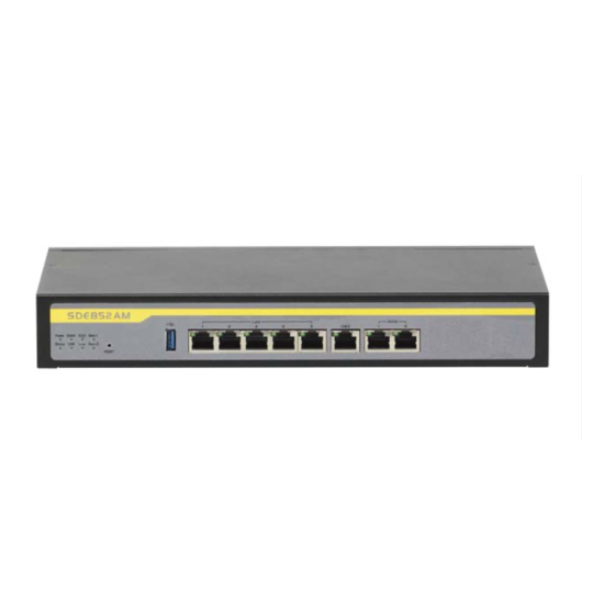
Multi-Service Gateway with WLAN Controller 1.2.3 Hardware Configuration Rear View: SDE852-00001 Power Console Port ON/OFF (DB9) Switch Receptor for Power Cable SDE852 User Manual... - Page 10 Multi-Service Gateway with WLAN Controller Front View: SDE852-00001 Reset Auto MDI/MDIX RJ-45 Ports Button 2x GbE WAN to connect Internet, 1x GbE DMZ to connect Local Server 5x GbE LAN to connect local devices SDE852 User Manual...
-
Page 11: Led Indicators
Multi-Service Gateway with WLAN Controller 1.2.4 LED Indicators SDE852-00001 Description OFF: Device is powered down. Power Green: Device is powered on. Green in flash: Device is in normal operation. Status Green in fast flash: Device is in recovery mode or abnormal state. -
Page 12: Chapter 2 Getting Started
Multi-Service Gateway with WLAN Controller Chapter 2 Getting Started 2.1 Connect Your Device Before you can use this product, you need to connect your PC or NB to this gateway first. You can connect your PC to one of LAN1~LAN5 ports through an Ethernet cable. 2.2 Easy Setup by Configuring Web UI You can browse web UI to configure the device. - Page 13 Multi-Service Gateway with WLAN Controller I. Wizard Select “Wizard” for basic network settings and VPN settings in a simple way. Or, you can go to Basic Network / Advanced Network / Applications / System to setup the configuration by your own selection. A.
- Page 14 Multi-Service Gateway with WLAN Controller Step 2: Change Password Password setting. You can change the login password of web UI here. It’s strongly recommending you to change this login password from default value. Press “Next” to continue. Step 3: Time Zone Time Zone setting.
- Page 15 Multi-Service Gateway with WLAN Controller Step 4-2: Ethernet (Dynamic IP Address) choosing Ethernet->Dynamic Address, you can input host name or registered MAC address when your ISP requests it. In most cases, you can leave them as blank and go next. This option is usually chosen when you get a dynamic IP address from ISP.
- Page 16 Multi-Service Gateway with WLAN Controller Step 4-6: 3G/4G If choosing 3G/4G->3G/4G, please make sure you have inserted SIM card. If not, please power off this gateway, and insert SIM card first. Then you can select “Auto-Detection” to finish dial-up profile automatically.
- Page 17 Multi-Service Gateway with WLAN Controller Step 7: Counting Down Configuration is completed. Press “Finish” button to close Setup Wizard and browser counts down for 65 seconds and provides you with “Click here” button to reconnect to the device. B. Configure with the VPN Setup Wizard Step 1 The VPN setup wizard will guide you to finish profiles of IPSec, PPTP, and L2TP...
- Page 18 Multi-Service Gateway with WLAN Controller Step 2-1: IPSec If choosing IPSec, there are two options of tunnel scenario can be chosen. “Site to Site” is for two offices to create VPN tunnel. “Dynamic VPN” is for remote users to connect to office. For other options, please Advanced...
- Page 19 Multi-Service Gateway with WLAN Controller If choosing PPTP Server, please select options of authentication and MPPE. You also need to create a set of username and password for PPTP clients. In this wizard, you can only create one user account. If you want to create more user accounts, please Advanced...
- Page 20 Multi-Service Gateway with WLAN Controller If choosing L2TP Server, please select options of authentication and MPPE. You also need to create a set of username and password for L2TP clients. In this wizard, you can only create one user account. If you want to create more user accounts, please Advanced...
- Page 21 Multi-Service Gateway with WLAN Controller 1. 3G/4G Icon: Indicates if 3G/4G connection is established or not. 2. xDSL/Cable Icon: Indicates if Ethernet WAN connection is established or not. 3. Wired Client Icon: Indicates how many Ethernet clients are connected now. WAN Interface IPv4 Network Status Display WAN type, IPv4 information, MAC information, and connection status of multiple WAN interfaces in IPv4 networking.
- Page 22 Multi-Service Gateway with WLAN Controller Internet Traffic Statistics Display number of transmitted packets and received packets of each WAN interface. Device Time Display current time information of device. B. Firewall Status In Firewall Status page, you can review lots information of filter status, including Packet Filters, URL Blocking, Web Content Filters, MAC Control, Application Filters, IPS and other options of firewall.
- Page 23 Multi-Service Gateway with WLAN Controller Application Filters Display all activated rules of application filters Display all activated rules of IPS. Options Display option settings of firewall. C. VPN Status In VPN Status page, you can review lots information of VPN status, including IPSec status, PPTP Server status, PPTP Client status, L2TP Server status, L2TP Client status and SSL VPN Server status.
- Page 24 Multi-Service Gateway with WLAN Controller Display the status of all activated accounts of L2TP server. L2TP Client Status Display the status of all activated L2TP clients. SSL VPN Server Status Display the status of all activated accounts of SSL VPN server. D.
-
Page 25: Chapter 3 Making Configurations
Multi-Service Gateway with WLAN Controller Chapter 3 Making Configurations Whenever you want to configure your network or this device, you can access the Configuration Menu by opening the web-browser and typing in the IP Address of the device. The default IP Address is: 192.168.123.254. In the configuration section you may want to check the connection status of the device, to do Basic or Advanced Network setup or to check the system status. -
Page 26: Wan Setup
Multi-Service Gateway with WLAN Controller 3.1.1 WAN Setup This device is equipped with two or three WAN Interfaces to support different WAN types of connections. You can configure one by one to get proper internet connection setup. Ethernet WAN: The product has one or two RJ45 Ethernet WAN port(s). Please plug in RJ45 cable from your external DSL modem and follow UI setting to setup. - Page 27 Multi-Service Gateway with WLAN Controller Click on the “Edit” button for each WAN interface and you can get the detail physical interface settings and then configure the settings as well. By default, the WAN-1 interface is forced to “Always-on” mode, and operates as the primary internet connection;...
-
Page 28: Internet Setup
Multi-Service Gateway with WLAN Controller Line Speed: You can specify the downstream / upstream speed (Kbps) for the corresponding WAN connection. Such information will be referred in QoS and load balance function to manage the traffic load for each WAN connection. VLAN Tagging: If your ISP required a VLAN tag been inserted into the WAN packets, you can enable this setting, and enter the specified tag value. - Page 29 Multi-Service Gateway with WLAN Controller WAN settings and then configure the settings as well. Dynamic IP Address 1. WAN Type: choose “Dynamic IP Address” from the drop list 2. Host Name: Optional, required by some ISPs, for example, @Home. 3.
- Page 30 Multi-Service Gateway with WLAN Controller Maximum Idle Time. If choosing “Manually”, this gateway won’t start to establish WAN connection until you press “Connect” button on web UI. After that, this gateway will disconnect WAN connection if idle time reaches value of Maximum Idle Time.
- Page 31 Multi-Service Gateway with WLAN Controller auto mode or select by Auto ,IGMP v1, IGMP v2, IGMP v3. 7. WAN IP alias: The device supports 2 WAN IP addresses for a physical interface, one is for primary connection that provides users/devices in the LAN to access Internet;...
- Page 32 Multi-Service Gateway with WLAN Controller Maximum Idle Time. If choosing “Manually”, this gateway won’t start to establish WAN connection until you press “Connect” button on web UI. After that, this gateway will disconnect WAN connection if idle time reaches value of Maximum Idle Time.
- Page 33 Multi-Service Gateway with WLAN Controller option, you have to specify additional “WAN IP Address”, “WAN Subnet Mask”, and “WAN Gateway” settings provided by your ISP. 3. Server IP Address / Name: The IP address of the PPTP server and designated Gateway provided by your ISP.
- Page 34 Multi-Service Gateway with WLAN Controller 10. NAT : If you disable this option, it will act with a non-NAT function. 11. IGMP: Enable or disable multicast traffics from the internet. You may enable as auto mode or select by Auto ,IGMP v1, IGMP v2, IGMP v3. 12.
- Page 35 Multi-Service Gateway with WLAN Controller 3. Server IP Address / Name: The IP address of the PPTP server and designated Gateway provided by your ISP. 4. L2TP Account and Password: The account and password your ISP assigned to you. Please note the account and password is case sensitive. For security concern, the password you input won’t be displayed on web UI.
-
Page 36: Wireless Wan - 3G/4G
Multi-Service Gateway with WLAN Controller one is for primary connection that provides users/devices in the LAN to access Internet; the other is a virtual connection that let remote user to manage this device. Afterwards, click on “Save” to store your settings or click “Undo” to give up the changes. - Page 37 Multi-Service Gateway with WLAN Controller 3. APN / PIN Code: Enter the PIN Code for your SIM card(Optional) 4. Dialed Number: Enter the dialed number that is provided by your ISP. 5. Account, Password: Enter the account / Password that is provided by your ISP(Optional).
-
Page 38: Load Balance
Multi-Service Gateway with WLAN Controller schedule at System -> Scheduling menu. 10. MTU: MTU refers to Maximum Transmit Unit. Different WAN types of connection will have different value. You can leave it with 0 (Auto) if you are not sure about this setting. - Page 39 Multi-Service Gateway with WLAN Controller If you choose the “By Smart Weight” strategy, No any other setting is required. This device will automatically allocate the outbound traffics to each WAN interface. SDE852 User Manual...
- Page 40 Multi-Service Gateway with WLAN Controller By Priority: 1. Priority: If you choose the “By Priority” strategy, you have to further specify the outbound traffic percentage for each WAN interface. The load balancing mechanism will follow these settings to allocate proper traffics for each WAN to access the internet.
-
Page 41: Lan & Vlan
Multi-Service Gateway with WLAN Controller 1. Source IP Address: Enter the expected Source IP Address for the load balance policy. It can be “Any”, “Subnet”, “IP Range”, or “Single IP”. Just choose one type of the source IP address, and specify its value as well. If you don’t want to specify a certain source IP address for this policy, just leave it as “Any”... -
Page 42: Network Setting
Multi-Service Gateway with WLAN Controller 3.1.2.1 Network Setting Please follow the following instructions to do IPv4 Network Setup. 1. LAN IP Address: The local IP address of this device. The computer on your network must use the LAN IP address of this device as their Default Gateway. You can change it if necessary. -
Page 43: Lan & Vlan
Multi-Service Gateway with WLAN Controller Afterwards, click on “Save” to store your settings or click “Undo” to give up the changes. 3.1.2.2 LAN & VLAN This section provides a brief description of VLANs and explains how to create, and modify virtual LANs which are more commonly known as VLANs. A VLAN is a group of ports that form a logical network under a certain switch or router device. - Page 44 Multi-Service Gateway with WLAN Controller In SMB or Company, Administrator scheme out 3 segments, Lab ,Office and Lobby. Furthermore, The device is Wireless Gateway, Administrator can install Port2 and VAP1 (SSID:Staff) DHCP1,Lab is Port3 and DHCP2,Port4 and VAP8 (SSID:Guest) DHCP3 in Lobby. ...
- Page 45 Multi-Service Gateway with WLAN Controller Port-Based VLAN - Bridge applications with ISP In some cases, ISP may need Gateway to support “VLAN tag” for certain kinds of services (e.g. IPTV) to work properly. SDE852 User Manual...
-
Page 46: Port-Based Vlan
Multi-Service Gateway with WLAN Controller Tag-Based VLAN Another type of VLAN is the tag-based VLAN and called VLAN Trunk. VLAN membership in a tagged VLAN is determined by information within the frames that are received on a port. 3.1.2.2.2 Port-Based VLAN A port-based VLAN is a group of ports on a Ethernet switch or router that form a logical Ethernet segment. - Page 47 Multi-Service Gateway with WLAN Controller By default, all the 5 LAN ports and 1 DMZ Port belong to one VLAN, and this VLAN is a NAT type network, besides DMZ Port, all the local device IP addresses are allocated by DHCP server 1. If you want to divide them into different VLANs, click on the “Edit”...
-
Page 48: Tag-Based Vlan
Multi-Service Gateway with WLAN Controller Support 2 access Policies. One is Internet Access Policy and the other is Intranet access Policy which means if Ethernet Ports or VAPs with different VLAN ID Communicate each other. Afterwards, click on “Save” to store your settings or click “Undo” to give up the changes. - Page 49 Multi-Service Gateway with WLAN Controller Besides DMZ Port, all the LAN ports and virtual APs belong to one VLAN, and this VLAN ID is forced to “1”. It is a special tag based VLAN for device to operated, there is no tag required for this default VLAN ID. If you want to configure your own tag-based VLANs, click on the “Edit”...
-
Page 50: Ipv6 Setup
Multi-Service Gateway with WLAN Controller Afterwards, click on “Save” to store your settings or click “Undo” to give up the changes. 3.1.3 IPv6 Setup The growth of the Internet has created a need for more addresses than are possible with IPv4. - Page 51 Multi-Service Gateway with WLAN Controller 2. Subnet Prefix Length: Enter the Prefix length of the Subnet Mask here; The subnet mask was the forerunner of the modern IP address prefix length. For example a subnet mask of 255.255.255.0 conveys exactly the same information as a prefix length of /24, a subnet mask of 255.255.255.240 is equivalent to a prefix length of /28.
-
Page 52: Dhcp V6
Multi-Service Gateway with WLAN Controller 3.1.4.2 DHCP v6 When “DHCPv6” is selected you need to do the following settings: DHCPv6 WAN Type Configuration: 1. DNS: You may select to obtain DNS server address from Server or entry IPv6 address Primary DNS address and secondary DNS address. 2. -
Page 53: Pppoev6
Multi-Service Gateway with WLAN Controller for immediate advertisements, rather than waiting for the next periodic ones to arrive; if and only if no advertisements are forthcoming, the host may retransmit the solicitation a small number of times, but then must desist from sending any more solicitations. -
Page 54: To 4
Multi-Service Gateway with WLAN Controller Address auto configuration settings: 10. Auto-configuration: Disable or enable this auto configuration setting. 11. Auto-configuration type: You may set stateless or stateful (Dynamic IPv6). 12. Router advertisement Lifetime: You can set the time for the period that the router send (broadcast) its router advertisement. -
Page 55: In 4
Multi-Service Gateway with WLAN Controller LAN Configuration: 4. Global Address: Please entry global Address. 5. LAN IPv6 address settings: Please enter “LAN IPv6 address” and ignore the “LAN IPv6 Link-Local address”. Address auto configuration settings: 6. Auto-configuration: Disable or enable this auto configuration setting. 7. -
Page 56: 6Rd
Multi-Service Gateway with WLAN Controller address. 3. MLD Snooping : MLD snooping, IPv6 multicast data is selectively forwarded to a list of ports that want to receive the data, instead of being flooded to all ports in a VLAN. This list is constructed by snooping IPv6 multicast control packets. If necessary in your environment, please enable this feature. - Page 57 Multi-Service Gateway with WLAN Controller 1. Remote IPv4 and Prefix: you may add remote IPv4 address and local IPv6 address, then set DNS address manually for Primary DNS address and secondary DNS address. 2. DNS: Please entry IPv6 address Primary DNS address and secondary DNS address.
-
Page 58: Nat / Bridge
Multi-Service Gateway with WLAN Controller 3.1.4 NAT / Bridge 3.1.4.1 Configuration 1. NAT Loopback: Allow you to access the WAN IP address from inside your local network. This is useful when you run a server inside your network. For an example, if you set a mail server at LAN side, your local devices can access this mail server through gateway’s WAN IP address. -
Page 59: Virtual Computers
Multi-Service Gateway with WLAN Controller A virtual server is defined as a Service Port, and all requests to this port will be redirected to the computer specified by the Server IP. Virtual Server can work with Scheduling Rules, and give user more flexibility on Access control. For the details, please refer to Scheduling Rule. -
Page 60: Special Ap & Alg
Multi-Service Gateway with WLAN Controller 1. Global IP: Enter the global IP address assigned by your ISP. 2. Local IP: Enter the local IP address of your LAN PC corresponding to the global IP address. 3. Enable: Check this item to enable the Virtual Computer feature. 3.1.4.3 Special AP &... -
Page 61: Dmz
Multi-Service Gateway with WLAN Controller Some applications require multiple connections, like Internet games, Video conferencing, Internet telephony, etc. Because of the firewall function, these applications cannot work with a pure NAT router. The Special Applications feature allows some of these applications to work with this product. This device provides some predefined settings. - Page 62 Multi-Service Gateway with WLAN Controller 2. DHCP Relay: DHCP Relay Agent component relays DHCP messages between DHCP clients and DHCP servers on different IP networks. Because DHCP is a broadcast-based protocol, by default its packets do not pass through routers. If you need this feature in the environment, please enables it.
-
Page 63: Routing
Multi-Service Gateway with WLAN Controller 3.1.5 Routing If you have more than one routers and subnets, you will need to enable routing function to allow packets to find proper routing path and allow different subnets to communicate with each other. 3.1.5.1 Static Routing For static routing, you can specify up to 32 routing rules. -
Page 64: Dynamic Routing
Multi-Service Gateway with WLAN Controller Destination: Enter the subnet network of routed destination. Subnet Mask: Input your Subnet mask. Subnet mask defines the range of IP address in destination network. Gateway: The IP address of gateway that you want to route for this destination subnet network. - Page 65 Multi-Service Gateway with WLAN Controller RIPv2 only if you have different subnets in your network. Otherwise, please select RIPv1 if you need this protocol. 2. OSPF: OSPF is an interior gateway protocol that routes Internet Protocol (IP) packets solely within a single routing domain (autonomous system). It gathers link state information from available routers and constructs a topology map of the network.
-
Page 66: Routing Information
Multi-Service Gateway with WLAN Controller finished setting, click on “Save” to store your settings or click “Undo” to give up the changes. 3.1.5.3 Routing Information A routing table, or routing information base (RIB), is a data table stored in a router or a networked computer that lists the routes to particular network destinations, and in some cases, metrics (distances) associated with those routes. -
Page 67: Dhcp Server
Multi-Service Gateway with WLAN Controller simpler way is to apply a domain name to 3-party DDNS service provider. It can be free or charged. To host your server on a changing IP address, you have to use dynamic domain name service (DDNS). Therefore, anyone wishing to reach your host only needs to know the name of it. - Page 68 Multi-Service Gateway with WLAN Controller 3. Subnet Mask: Input your Subnet mask. Subnet mask defines how many clients are allowed in one network or subnet. The default subnet mask is 255.255.255.0, and it means maximum 254 IP addresses are allowed in this subnet. However, one of them is occupied by LAN IP address of this gateway, so there are maximum 253 clients allowed in LAN network.
-
Page 69: Advanced Network
Multi-Service Gateway with WLAN Controller DNS Servers 8. Primary WINS/Secondary WINS: Optional. This feature allows you to assign a WINS Servers 9. Gateway: Optional. Gateway address would be the IP address of an alternate Gateway. This function enables you to assign another gateway to your local computer when DHCP server offers IP address. -
Page 70: Firewall
Multi-Service Gateway with WLAN Controller 3.2.1 Firewall The firewall functions include Packet Filters, URL Blocking, Web Content Filters, MAC Control, Application Filters, IPS and some firewall options. 3.2.1.1 Configuration One Firewall Enable check box lets you activate all firewall functions that you want. 3.2.1.2 Packet Filters Packet Filters function can let you define both outbound filter and inbound filter rules by specifying the source IP and destination IP in a rule. -
Page 71: Configuration
Multi-Service Gateway with WLAN Controller 3.2.1.2.1 Configuration You can enable packet filter function here. And select one of the two filtering policies as follows. The first one is to define the black list. System will block the packets that match the active filter rules. However, the second one is the white list. System will allow the packets to pass the gateway, which match the active filter rules. -
Page 72: Packet Filter Rule Configuration
Multi-Service Gateway with WLAN Controller 3.2.1.2.3 Packet Filter Rule Configuration It supports the adding of one new rule or the editing of one existed rule. There are some parameters need to be specified in one packet filter rule. They are Rule Name, From Interface, To Interface, Source IP, Destination IP, Destination Port, Protocol, Time Schedule and finally, the rule enable. -
Page 73: Url Blocking
Multi-Service Gateway with WLAN Controller 7. Protocol: Specify which packet protocol is to be filtered. It can be TCP, UDP, or Both. 8. Time Schedule: The rule can be turn on according to the schedule rule you specified, and give user more flexibility on access control. By default, it is always turned on when the rule is enabled. -
Page 74: Configuration
Multi-Service Gateway with WLAN Controller 3.2.1.3.1 Configuration 1. URL Blocking: Check the enable box if you want to activate URL Blocking function. 2. Black List / White List: Select one of the two filtering policies for the defined rules in URL Blocking Rule List. ... -
Page 75: Url Blocking Rule Configuration
Multi-Service Gateway with WLAN Controller 3.2.1.3.3 URL Blocking Rule Configuration It supports the adding of one new rule or the editing of one existed rule. There are some parameters need to be specified in one URL blocking rule. They are Rule Name, URL / Domain Name / Keyword, Destination Port, Time Schedule and finally, the rule enable. -
Page 76: Configuration
Multi-Service Gateway with WLAN Controller like ".exe", ".bat" (applications), "mpeg” (video), and block HTML requests with some script types, like Java Applet, Java Scripts, cookies and Active X. 3.2.1.4.1 Configuration 1. Web Content Filters: Check the Enable box if you want to enable Web Content Filters function. -
Page 77: Web Content Filter Configuration
Multi-Service Gateway with WLAN Controller 3.2.1.4.3 Web Content Filter Configuration It supports the adding of one new rule or the editing of one existed rule. There are some parameters need to be specified in one Web Content Filter rule. They are Rule Name, User-defined File Extension List, Time Schedule and finally, the rule enable. -
Page 78: Configuration
Multi-Service Gateway with WLAN Controller 3.2.1.5.1 Configuration 1. MAC Control: Check the “Enable” box to activate the MAC Control function. All of the settings in this page will take effect only when “Enable” is checked. 2. Black List / White List: Select one of the two filtering policies for the defined rules. -
Page 79: Mac Control Rule Configuration
Multi-Service Gateway with WLAN Controller Control Rule List. Besides, unnecessary rules can be removed by checking the “Select” box for those rules and then clicking on the “Delete” command button at the MAC Control Rule List caption. 3.2.1.5.3 MAC Control Rule Configuration It supports the adding of one new rule or the editing of one existed rule. -
Page 80: Configuration
Multi-Service Gateway with WLAN Controller 3.2.1.6.1 Configuration 1. Application Filters: Check the “Enable” box to activate the Application Filters function. All of the settings in this page will take effect only when “Enable” is checked. 2. Log Alert: Enable the log alerting so that system will record Application Filter events when filtering rules are fired. -
Page 81: Options
Multi-Service Gateway with WLAN Controller system will record Intrusion events when corresponding intrusions are detected. 3.2.1.8 Options 1. Stealth Mode: Enable this feature, this device will not respond to port scans from the WAN so that makes it less susceptible to discovery and attacks on the Internet. -
Page 82: Qos & Bwm
It is indeed required that an access gateway satisfies the requirements of latency-critical applications, minimum access right guarantee, fair bandwidth usage for same subscribed condition and flexible bandwidth management. AMIT Security Gateway provides a Rule-based QoS to carry out the requirements. -
Page 83: Configuration
Multi-Service Gateway with WLAN Controller 3.2.2.1 Configuration QoS on Multiple WAN Interfaces QoS on all WAN interfaces satisfies the requirements of latency-critical applications, minimum access right guarantee, fair bandwidth usage for same subscribed condition and flexible bandwidth management in a more flexible approach. -
Page 84: Rule-Based Qos
Multi-Service Gateway with WLAN Controller 1. WAN Interface: Select the WAN interface to configure. 2. Bandwidth of Upstream: The maximum bandwidth of uplink in Mbps. 3. Bandwidth of Downstream: The maximum bandwidth of downlink in Mbps. 4. Total Connection Sessions: Input the maximum number of connection sessions for the WAN interface. -
Page 85: Configuration
Multi-Service Gateway with WLAN Controller There are 4 resources can be applied in a QoS rule: bandwidth, connection sessions, priority queues and DiffServ Code Point (DSCP). Control function that acts on target objects for specific services of packet flow is based on these resources. ... -
Page 86: Qos Rule Configuration
Multi-Service Gateway with WLAN Controller 1. Add: After you enabled the rule-based QoS function, you can click on the “Add” button to create a new QoS rule. 2. Delete: After you selected some QoS rules by checking the “Select” box for each rule, you can click on the “Delete”... - Page 87 Multi-Service Gateway with WLAN Controller By default, it is “All”. It defines “what” kinds of service packets need to be managed. When “DSCP” is selected, another “DiffServ CodePoint” value must be specified. DSCP means DiffServ Code Point, as known as advanced TOS. You can choose this option if your local service gateway supports DSCP tags.
- Page 88 Multi-Service Gateway with WLAN Controller 4. Resource: There are 4 resources can be chosen to control in a QoS rule. They are “Bandwidth”, “Connection Sessions”, “Priority Queues” and “DiffServ Code Points”. 5. Control Function: It depends on the chosen resource. For “Bandwidth” resource, the control function is “Set MINR &...
- Page 89 Multi-Service Gateway with WLAN Controller 9. Enable: Check the box if you want to enable the rule. Each rule can be enabled or disabled individually. Afterwards, click on “Save” to store your settings or click “Undo” to give up the changes.
-
Page 90: Vpn Setup
Multi-Service Gateway with WLAN Controller Interface: Select “WAN-1”. Group: Select “IP” and enter IP range: 192.168.75.10 ~ 40. Service: Select “ALL”. Resource: Select “Connection Sessions”. Control Function: Select “Set Session Limitation”, and set session number to 20000. QoS Direction: Select “Outbound” for outbound traffic only. It is for the client devices under the gateway to establish multiple sessions with servers in the Internet. -
Page 91: Ipsec Vpn Tunnel Scenarios
Multi-Service Gateway with WLAN Controller An IPSec VPN tunnel is established between IPSec client and server. Sometimes, we call the IPSec VPN client as the initiator and the IPSec VPN server as the responder. There are two phases to negotiate between the initiator and responder during tunnel establishment, IKE phase and IPSec phase. -
Page 92: Ipsec Configuration
Multi-Service Gateway with WLAN Controller There is one more advanced IPSec VPN application: Site to Site – Support Full Tunnel Application When Full Tunnel function of remote Business Security Gateway is enabled, all data traffic from remote clients behind remote Business Security Gateway will goes over the VPN tunnel. -
Page 93: Tunnel List & Status
Multi-Service Gateway with WLAN Controller IPSec: You could trigger the function of IPSec VPN if you check “Enable” box. NetBIOS over IPSec: If you would like two Intranets behind two Business Security Gateways to receive the NetBIOS packets from Network Neighborhood, you have to check “Enable”... -
Page 94: Tunnel Configuration
Multi-Service Gateway with WLAN Controller 3.2.3.1.4 Tunnel Configuration Tunnel Name: Enter the name of tunnel. Interface: Decide the WAN Interface to establish the tunnel. Operation Mode: Default is “Always on” and other options depend on product models. Tunnel Scenario: Support “Site to Site” and “Dynamic VPN”. Encapsulation Protocol: Default is ESP and other options depend on product models. -
Page 95: Authentication
Multi-Service Gateway with WLAN Controller subnet domain for the local devices connected via the VPN tunnel. Full Tunnel: All traffic from Intranet of Business Security Gateway goes over the IPSec VPN tunnel if these packets don’t match the Remote Subnet of other IPSec tunnels. -
Page 96: Ike Proposal Definition
Multi-Service Gateway with WLAN Controller Negotiation Mode: Choose Main Mode or Aggressive Mode: Main Mode provides identity protection by authenticating peer identities when pre-shared keys are used. The IKE SA’s are used to protect the security negotiations. Aggressive mode will accelerate the establishing speed of VPN tunnel, but the device will suffer from less security in the meanwhile. -
Page 97: Ipsec Phase
Multi-Service Gateway with WLAN Controller There are 4 IKE proposals can be defined by you and used in IKE phase of negotiation between two VPN peers. Encryption: There are six algorithms can be selected: DES, 3DES, AES-auto, AES-128, AES-192, and AES-256. Authentication: There are five algorithms can be selected: None, MD5, SHA1, SHA2-256 and SHA2-512. -
Page 98: Manual Proposal
Multi-Service Gateway with WLAN Controller Group 2 (MODP1024), Group 5 (MODP1536) and Group14 ~ 18. Once the PFS Group is selected in one IPSec proposal, the one in other 3 IPSec proposals uses the same choice. Enable: Check this box to enable the IKE Proposal during tunnel establishing. 3.2.3.1.11 Manual Proposal When “Manually”... -
Page 99: Pptp / L2Tp Vpn Tunnel Scenarios
Multi-Service Gateway with WLAN Controller implement security functionality. However, the most common PPTP implementation shipping with the Microsoft Windows product families implements various levels of authentication and encryption natively as standard features of the Windows PPTP stack. The intended use of this protocol is to provide security levels and remote access levels comparable with typical VPN products. -
Page 100: Pptp Server Configuration
Multi-Service Gateway with WLAN Controller PPTP: Check the “Enable” box to activate PPTP client and server functions. Client/Server: Choose Server or Client to configure corresponding role of PPTP VPN tunnels for the Business Security Gateway beneath the choosing screen 3.2.3.2.1 PPTP Server Configuration The Business Security Gateway can behave as a PPTP server, and it allows remote hosts to access LAN servers behind the PPTP server. -
Page 101: User Account List
Multi-Service Gateway with WLAN Controller The user name and connection information for each connected PPTP client to the PPTP server of the Business Security Gateway will be shown in this table. Refresh: To refresh the PPTP Server Status each 2 seconds by clicking on the “Refresh”... -
Page 102: Pptp Client List & Status
Multi-Service Gateway with WLAN Controller client hosts in the Intranet of Business Security Gateway can access LAN servers behind the PPTP server. PPTP Client: Enable or disable PPTP client function. 3.2.3.2.6 PPTP Client List & Status You can add new up to 22 different PPTP client tunnels by clicking on the “Add” button, and modify each tunnel configuration by clicking on the corresponding “Edit”... - Page 103 Multi-Service Gateway with WLAN Controller PPTP Client Name: The name of this tunnel. Operation Mode: Default is “Always on” and other options depend on product models. Peer IP/Domain: The IP address or Domain name of remote PPTP server. User Name: The user name which can be validated by remote PPTP server. Password: The password which can be validated by remote PPTP server.
-
Page 104: L2Tp
Multi-Service Gateway with WLAN Controller authentication methods. 10. NAT before Tunneling: Check the “Enable” box to let hosts in the Intranet of Business Security Gateway can go to access Internet via remote PPTP server. By default, it is enabled. However, if you want the remote PPTP Server to monitor the Intranet of local Business Security Gateway, the option can’t be enabled. -
Page 105: L2Tp Server Status
Multi-Service Gateway with WLAN Controller 1. L2TP Server: Enable or disable L2TP server function. 2. L2TP over IPSec: L2TP over IPSec VPNs allow you to transport data over the Internet, while still maintaining a high level of security to protect data. Enter a Pre-shared key that system will use it in IPSec tunneling. -
Page 106: User Account List
Multi-Service Gateway with WLAN Controller dialing in L2TP clients by clicking on the “Disconnect” button. 3.2.3.3.3 User Account List You can input up to 10 different user accounts for dialing in L2TP server. Add: You can add one new user account by clicking on the “Add” button. Delete: Delete selected user accounts by checking the “Select”... -
Page 107: L2Tp Client Configuration
Multi-Service Gateway with WLAN Controller You can add new up to 22 different L2TP client tunnels by clicking on the “Add” button, and modify each tunnel configuration by clicking on the corresponding “Edit” button at the end of each existed tunnel. Add: You can add one new L2TP client tunnel by clicking on the “Add”... -
Page 108: Gre
Multi-Service Gateway with WLAN Controller Intranet of Business Security Gateway goes over this L2TP tunnel if these packets don’t match the Peer Subnet of other L2TP tunnels. There is only one L2TP tunnel to own the “Default Gateway” property. However, when “Peer Subnet”... -
Page 109: Gre Configuration
Multi-Service Gateway with WLAN Controller 3.2.3.4.2 GRE Configuration GRE Tunnel: Check the “Enable” box to activate the GRE tunnel function 3.2.3.4.3 GRE Tunnel Definitions Add: You can add one new GRE tunnel by clicking on the “Add” button. Delete: Delete selected tunnels by checking the “Select” box at the end of each tunnel list and then clicking on the “Delete”... -
Page 110: Redundancy
Multi-Service Gateway with WLAN Controller Tunnel: Enable or disable this GRE tunnel. Tunnel Name: The name of this GRE tunnel. Tunnel IP: The gateway IP address of Business Security Gateway. Peer IP: Enter the IP address of remote peer that you want to connect. Key: Enter the password to establish GRE tunnel with remote host. - Page 111 Multi-Service Gateway with WLAN Controller The protocol achieves this by creation of virtual routers, which are an abstract representation of multiple routers, i.e. master and backup routers, acting as a group. The default gateway of a participating host is assigned to the virtual router instead of a physical router.
-
Page 112: System Management
Multi-Service Gateway with WLAN Controller 3.2.5 System Management This device supports many system management protocols, such as TR-069, SNMP, Telnet with CLI and UPnP. You can finish those configurations in this sub-section. 3.2.5.1 TR-069 TR-069 (Technical Report 069) is a Broadband Forum technical specification entitled CPE WAN Management Protocol (CWMP). - Page 113 IF-MIB, IP-MIB, TCP-MIB, UDP-MIB SMIv1 and SMIv2 SNMPv2-TM and SNMPv2-MIB AMIB (AMIT Private MIB) 1. Enable SNMP: You can check “Local(LAN)”, “Remote(WAN)” or both to enable SNMP function. If “Local(LAN)” is checked, this device will respond to the request...
-
Page 114: Telnet With Cli
Multi-Service Gateway with WLAN Controller from LAN. If “Remote(WAN)” is checked, this device will respond to be request from WAN. 2. WAN Access IP Address: If you want to limit the remote SNMP access to specific computer, please enter the PC`s IP address. The default value is 0.0.0.0, and it means that any internet connected computer can get some information of the device with SNMP protocol. - Page 115 Multi-Service Gateway with WLAN Controller UPnP Internet Gateway Device (IGD) Standardized Device Control Protocol is a NAT port mapping protocol and is supported by some NAT routers. It is a common communication protocol of automatically configuring port forwarding. Applications using peer-to-peer networks, multiplayer gaming, and remote assistance programs need a way to communicate through home and business gateways.
-
Page 116: Applications
Multi-Service Gateway with WLAN Controller Applications 3.3.1 AP Management 3.3.1.1 Configuration 3.3.1.1.1 AP Management Configuration AP Management: Check the Enable box if you want to enable this function. 3.3.1.1.2 AP Configuration Proposal List It is a list of AP Proposals and APC and APW proposal templates in default. You can add one new Proposal by clicking on the “Add”... -
Page 117: Ap List
Multi-Service Gateway with WLAN Controller 3.3.1.2 AP List 3.3.1.2.1 Trusted AP List & Status SDE Gateway will discover and show some information of Trusted APs in List. You can select one AP to click “Allow”, “Deny”, ”Edit”, ”Event” and ”Apply” button to configure trusted APs. -
Page 118: Ap Configuration
Multi-Service Gateway with WLAN Controller Deny: It means Stations which are connected to corresponded AP can deny Intranet Network. Edit: Click “Edit” to configure Trusted AP. Event: You can some important logs of trusted AP to click “Event” Button. 3.3.1.3 AP Configuration 3.3.1.3.1 AP Configuration Admin user can configure related Settings ,like WiFi or System of trusted APs. -
Page 119: Captive Portal
Multi-Service Gateway with WLAN Controller 3.3.2 Captive Portal 3.3.2.1 Captive Portal Configuration SDE Gateway builds in Web Portal and Authentication Server. If necessary, please enable this feature. NOTE: All Internet Packets will forward to web portal of SDE Gateway when enabled this feature. -
Page 120: System
Multi-Service Gateway with WLAN Controller System In the System section you can see system related information and system logs, use system tools for system update and do some network tests. Besides, you can also define some time scheduling rules here to be applied at various applications in the device system. Administrator Time-out in seconds defines the idle time-out for administrator to configure the device by using Web UI. -
Page 121: Change Password
Multi-Service Gateway with WLAN Controller 3.4.1.1 Change Password You can change the System Password here. We strongly recommend you to change the system password for security reason. Click on “Save” to store your settings or click “Undo” to give up the changes. 1. -
Page 122: System Status
Multi-Service Gateway with WLAN Controller 3.4.1.3 System Status You can view the System Logs in Web UI. You also can send the logs to specific email accounts periodically or instantly by clicking on the “Email Now” command button. 1. Web Log: You can select the log types to be collected in the web log area. There are “System”, “Attacks”, “Drop”, and “Debug”... -
Page 123: System Tools
Multi-Service Gateway with WLAN Controller addresses. * E-mail Subject: The subject of email alert is optional. 4. Email Now: A command button to let you email out current web logs right now instead of the email alert period. 3.4.1.4 System Tools The device supports many system tools, including system time configuration, FW upgrading, system rebooting, system resetting to default, waking on LAN and configuration settings backup. - Page 124 Multi-Service Gateway with WLAN Controller Auto-Synchronization must be unchecked beforehand to do it. Above is the first way to setup system date and time. That is, it is the manual way. The second way is “Sync with Timer Server”. Based on your selection of time server in basic information configuration, system will communicate with time server by NTP Protocol to get system date and time after you click on the button.
-
Page 125: Scheduling
Multi-Service Gateway with WLAN Controller measuring transit delays of packets across an IP network. Traceroute proceeds unless all (three) sent packets are lost more than twice, then the connection is lost and the route cannot be evaluated. Ping, on the other hand, only computes the final round-trip times from the destination point. -
Page 126: User Management
Multi-Service Gateway with WLAN Controller 1. Enable: Enable or disable the scheduling function. 2. Add New Rule: To create a schedule rule, click the “Add New” button or the “Add New Rule” button at the bottom. When the next dialog popped out you can edit the Name of Rule, Policy, and set the schedule time (Week day, Start Time, and End Time). -
Page 127: User List
User groups with their owned name can be bound with multiple services, like X-Auth, NAS*, RADIUS, VPN, Accounting & Billing, SNMPv3 and CLI. BizServ gateway works in coordination with AMIT BizAP Controller that is a PC-based software for generating a list of user accounts with different levels automatically. -
Page 128: User Profile
Multi-Service Gateway with WLAN Controller User List can show the list of all user accounts and their status of on-line or offline in this window. You can add one new rule by clicking on the “Add” command button. But also you can modify some existed user accounts by clicking corresponding “Edit” command buttons at the end of each account record in the User List. -
Page 129: User Group
Multi-Service Gateway with WLAN Controller 1. User Name: The name of user account. 2. Password: The password of user account. 3. User Level: Supports 4 levels for you to select, including “Admin”, “Staff”, “Guest” and “Passenger”. Admin level of user account can let the user configure the device with fully control ability. -
Page 130: Mmi
Multi-Service Gateway with WLAN Controller 1. Group Name: The name of user group. 2. Multiple User Members: Click on the “Choice” to select multiple user accounts to join the group. 3. Multiple Bound Services: Supports 6 kinds of applications to be bound with the user group. - Page 131 Multi-Service Gateway with WLAN Controller the time-out is unlimited. SDE852 User Manual...
-
Page 132: Chaptor 4 Troubleshooting
Multi-Service Gateway with WLAN Controller CHAPTOR 4 Troubleshooting This Chapter provides solutions to problems for the installation and operation of the WiFi Broadband Router. You can refer to the following if you are having problems. 1 Why can’t I configure the router even the cable is plugged and the LED is lit? Do a Ping test to make sure that the WiFi Note: It is recommended that you... - Page 133 Multi-Service Gateway with WLAN Controller properly. Network adapter names will vary depending on your specific adapter. The installation steps listed below are applicable for all network adapters. Go to Start > Right click on “My Computer” > Properties. Select the Hardware Tab. Click Device Manager.
- Page 134 Multi-Service Gateway with WLAN Controller and then test the wireless connection. III. Disable all security settings such as WEP, and MAC Address Control. IV. Turn off the WiFi Broadband Router and the client, then restart it and then turn on the client again. Ensure that the LEDs are indicating normally.
- Page 135 Multi-Service Gateway with WLAN Controller Try changing the channel on the WiFi Broadband Router, and your Access Point and Wireless adapter to a different channel to avoid interference. III. Keep your product away from electrical devices that generate RF noise, like microwaves, monitors, electric motors, etc.
-
Page 136: Appendix A. Licensing Information
Multi-Service Gateway with WLAN Controller Appendix A. Licensing information This product includes copyrighted third-party software licensed under the terms of the GNU General Public License. Please refer to the GNU General Public License below to check the detailed terms of this license. The following parts of this product are subject to the GNU GPL, and those software packages are copyright by their respective authors. - Page 137 Multi-Service Gateway with WLAN Controller GNU GENERAL PUBLIC LICENSE Version 2, June 1991 Copyright (C) 1989, 1991 Free Software Foundation, Inc. 59 Temple Place, Suite 330, Boston, MA 02111-1307 USA Everyone is permitted to copy and distribute verbatim copies of this license document, but changing it is not allowed. Preamble The licenses for most software are designed to take away your freedom to share and change it.
- Page 138 Multi-Service Gateway with WLAN Controller GNU GENERAL PUBLIC LICENSE TERMS AND CONDITIONS FOR COPYING, DISTRIBUTION AND MODIFICATION 0. This License applies to any program or other work which contains a notice placed by the copyright holder saying it may be distributed under the terms of this General Public License. The "Program", below, refers to any such program or work, and a "work based on the Program"...
- Page 139 Multi-Service Gateway with WLAN Controller distributed under the terms of Sections 1 and 2 above on a medium customarily used for software interchange; or, b) Accompany it with a written offer, valid for at least three years, to give any third party, for a charge no more than your cost of physically performing source distribution, a complete machine-readable copy of the corresponding source code, to be distributed under the terms of Sections 1 and 2 above on a medium customarily used for software interchange;...
- Page 140 Multi-Service Gateway with WLAN Controller copyrighted interfaces, the original copyright holder who places the Program under this License may add an explicit geographical distribution limitation excluding those countries, so that distribution is permitted only in or among countries not thus excluded. In such case, this License incorporates the limitation as if written in the body of this License.
Need help?
Do you have a question about the SDE852-00001 and is the answer not in the manual?
Questions and answers