Table of Contents
Advertisement
Quick Links
Advertisement
Table of Contents

Related Manuals for Amit IOG761AM-0TDA1


Summary of Contents for Amit IOG761AM-0TDA1
- Page 1 Modbus Cellular Gateway IOG761AM‐0TDA1 User Manual ...
-
Page 2: Table Of Contents
Modbus Cellular Gateway Chapter 1 Introduction ............................7 1.1 Introduction .............................. 7 1.2 Contents List ............................8 1.2.1 Package Contents ........................... 8 1.3 Hardware Configuration .......................... 9 1.4 LED Indication ............................11 1.5 Installation & Maintenance Notice ......................13 1.5.1 SYSTEM REQUIREMENTS ..................... 13 ... - Page 3 Modbus Cellular Gateway 2.4.1 IPv6 Configuration........................98 2.5 Port Forwarding ..........................109 2.5.1 Configuration ..........................110 2.5.2 Virtual Server & Virtual Computer ................... 111 2.5.3 DMZ & Pass Through ....................... 117 2.5.4 Special AP & ALG (not supported) ..................120 2.5.5 IP Translation ..........................121 ...
- Page 4 Modbus Cellular Gateway 4.1.2 Virtual COM ..........................182 4.1.3 Modbus ............................. 192 4.2 Data Logging ............................200 4.2.1 Data Logging Configuration ..................... 203 4.2.2 Scheme Setup ..........................205 4.2.3 Log File Management ....................... 207 Chapter 5 Security .............................. 209 5.1 VPN ..............................209 ...
- Page 5 Modbus Cellular Gateway 6.2.5 Backup & Restore ........................309 6.2.6 Reboot & Reset ........................310 6.3 FTP ............................... 311 6.3.1 Server Configuration ......................... 312 6.3.2 User Account ..........................314 6.4 Diagnostic ............................315 6.4.1 Diagnostic Tools ........................315 6.4.2 Packet Analyzer ........................316 ...
- Page 6 Modbus Cellular Gateway 8.5 Statistics & Report ..........................372 8.5.1 Connection Session ........................372 8.5.2 Network Traffic (not supported) ....................373 8.5.3 Device Administration ......................374 8.5.4 Cellular Usage ........................... 375 Appendix A GPL WRITTEN OFFER........................ 376 ...
-
Page 7: Chapter 1 Introduction
Modbus Cellular Gateway Chapter 1 Introduction 1.1 Introduction Congratulations on your purchase of this outstanding product: Modbus Cellular Gateway. For M2M (Machine‐ to‐Machine) applications, AMIT Modbus Cellular Gateway is absolutely the right choice. With built‐in world‐ class 4G LTE and ADSL2+ module, you just need to insert SIM card from local mobile carrier to get to Internet. The redundant SIM and and mobile/ADSL combo‐WAN design provide a more reliable WAN connection for critical applications. By VPN tunneling technology, remote sites easily become a part of Intranet, and all data are transmitted in a secure (256‐bit AES encryption) link. To meet a variety of M2M application requirements, AMIT Modbus Cellular Gateway products are based on modular design. The IOG761 series product is loaded with luxuriant security features including VPN, firewall, NAT, port ... -
Page 8: Contents List
#Standard Package Items Description Contents Quantity IOG761AM‐0TDA1 1pcs Modbus Cellular Gateway Cellular Antenna 2pcs WiFi Antenna 2pcs Power Adapter (DC 12V/2A) 1pcs ) RJ45 Cable 1pcs RJ11 Cable 1pcs Console Cable 1pcs 8 Pin Terminal Block 1pcs CD 1pcs (Manual) Mounting Bracket 2pcs 1 The maximum power consumption of IOG761AM-0TDA1 is 15.5W. -
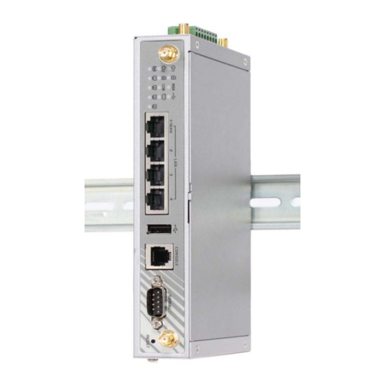
Page 9: Hardware Configuration
Modbus Cellular Gateway DIN‐Rail Bracket 1pcs 1.3 Hardware Configuration Front View USB Port RS-232/485 Reset Indicators Port Button Auto MDI/MDIX RJ45 Ports 3G/4G (Aux) Console 3G/4G (Main) 4x FE LAN to connect local devices Antenna Antenna Port ※ Reset Button ... - Page 10 Modbus Cellular Gateway Bottom View SIM B SIM A Slot Slot Left View 2.4G WiFi 2.4G WiFi Antenna Antenna Power Terminal Block ...
-
Page 11: Led Indication
Modbus Cellular Gateway Right View ADSL Port LED Indicators 1.4 LED Indication Front Panel Right Panel LED Color LED Icon Indication Description Power Source 1 Green Steady ON: Device is powered on by power source 1 Power Source 2 Green Steady ON: Device is powered on by power source 2 ) Steady ON: Wireless radio is enabled WLAN (WiFi) Green Flash: Data packets are transferred OFF: Wireless radio is disabled SIM A Green Steady ON: SIM card A is used SIM B Green Steady ON: SIM card B is used ... - Page 12 Modbus Cellular Gateway Steady ON: Ethernet connection of LAN is established LAN 1 ~ LAN 4 Green Flash: Data packets are transferred High 3G Signal Green Steady ON: The signal strength of 3G is strong Low 3G Signal Green Steady ON: The signal strength of 3G is weak USB Green Steady ON: If USB device is attached Serial Port Green Steady ON: If serial device is attached Steady ON: The sync with DSLAM has completed DSL Green Flash: Attempts to synchronize with the DSLAM Internet Green Steady ON: A DSL Internet connection is established ...
-
Page 13: Installation & Maintenance Notice
Modbus Cellular Gateway 1.5 Installation & Maintenance Notice 1.5.1 SYSTEM REQUIREMENTS A fast Ethernet RJ45 cable or DSL Line 3G/4G cellular service subscription Network Requirements IEEE 802.11n or 802.11b/ g wireless clients 10/100 Ethernet adapter on PC Computer with the following: Windows®, Macintosh, or Linux‐based operating system An installed Ethernet adapter Web-based Configuration Utility Browser Requirements: Requirements Internet Explorer 6.0 or higher Chrome 2.0 or higher Firefox 3.0 or higher Safari 3.0 or higher 1.5.2 WARNING Only use the power adapter that comes with the ... -
Page 14: Hot Surface Caution
Modbus Cellular Gateway 1.5.3 HOT SURFACE CAUTION CAUTION: The surface temperature for the metallic enclosure can be very high! Especially after operating for a long time, installed at a close cabinet without air conditioning support, or in a high ambient temperature space. DO NOT touch the hot surface with your fingers while servicing!! ... -
Page 15: Hardware Installation
Modbus Cellular Gateway 1.6 Hardware Installation This chapter describes how to install and configure the hardware 1.6.1 Mount the Unit The IOG761 series products can be mounted on a wall, horizontal plane, or DIN Rail in a cabinet with the mounting accessories (brackets or DIN‐rail kit). The mounting accessories are not screwed on the product ... -
Page 16: Connecting Power
Modbus Cellular Gateway 1.6.3 Connecting Power The IOG761 series product can be powered by connecting a power source to the terminal block . It supports dual 9 to 48VDC power inputs. Following picture is the power terminal block pin assignments. Please check carefully and connect to the right power requirements and polarity. There is a DC12V/2A power adapter in the package for you to easily connect DC power adapter to this terminal block. WARNNING: This commercial‐grade power adapter is mainly for ease of powering up the purchased device while initial configuration. It’s not for operating at wide temperature range environment. PLEASE PREPARE OR PURCHASE OTHER INDUSTRIAL‐GRADE POWER SUPPLY FOR POWERING UP THE DEVICE. For the dual power supply design on PWR1 and PWR2, the primary/backup power mode is implemented. If there is only one power source, no matter it is connected to PWR1 or PWR2, the device can be powered up ... -
Page 17: Connecting Di/Do Devices
Modbus Cellular Gateway 1.6.4 Connecting DI/DO Devices There are a DI and a DO ports together with power terminal block. Please refer to following specification to connect DI and DO devices. Mode Specification Trigger Voltage (high) Logic level 1: 5V~30V Digital Input Normal Voltage (low) Logic level 0: 0V~2.0V Voltage Depends on external device Digital Output (Relay Mode) maximum voltage is 30V ... -
Page 18: Connecting Serial Devices
Modbus Cellular Gateway 1.6.5 Connecting Serial Devices The IDG762 provides one standard serial port DB‐9 male connector. Connect the serial device to the unit DB‐9 male port with the right pin assignments of RS‐232/485 are shown as below. Pin1 Pin2 Pin3 Pin4 Pin5 Pin6 Pin7 Pin8 Pin9 RS‐232 DCD RXD TXD DTR GND DSR RTS CTS RI RS‐485 DATA+ DATA‐ GND 1.6.6 Connecting to the Network or a Host The IOG761 series provides four RJ45 ports to connect 10/100Mbps Ethernet. It can auto detect the transmission speed on the network and configure itself automatically. Connect the Ethernet cable to the RJ45 ... -
Page 19: Setup By Configuring Web Ui
Modbus Cellular Gateway 1.6.7 Setup by Configuring WEB UI You can browse web UI to configure the device. 4 Type in the IP Address (http://192.168.123.254) 5 When you see the login page, enter the password ‘admin’ and then click ‘Login’ button. 4 The default LAN IP address of this gateway is 192.168.123.254. If you change it, you need to type the new IP address 5 It’s strongly recommending you to change this login password from default value... -
Page 20: Chapter 2 Basic Network
Modbus Cellular Gateway Chapter 2 Basic Network 2.1 WAN & Uplink The gateway provides multiple WAN interfaces to let all client hosts in Intranet of the gateway access the Internet via ISP. But ISPs in the world apply various connection protocols to let gateways or user's devices dial in ISPs and then link to the Internet via different kinds of transmit media. So, the WAN Connection lets you specify the WAN Physical Interface, WAN Internet Setup and WAN Load Balance for Intranet to access Internet. For each WAN interface, you must specify its physical ... -
Page 21: Physical Interface
Modbus Cellular Gateway 2.1.1 Physical Interface M2M gateways are usually equipped with various WAN interfacess to support different WAN connection scenario for requirement. You can configure the WAN interface one by one to get proper internet connection setup. Refer to the product specification for the available WAN interfaces in the product you purchased. The first step to configure one WAN interface is to specify which kind of connection media to be used for the WAN connection, as shown in "Physical Interface" page. In "Physical Interface" page, there are two configuration windows, "Physical Interface List" and "Interface Configuration". ... - Page 22 Modbus Cellular Gateway Please MUST POWER OFF the gateway before you insert or remove SIM card. The SIM card can be damaged if you insert or remove SIM card while the gateway is in operation. Attention Operation Mode: There are three option items “Always on”, “Failover”, and “Disable” for the operation mode setting. ...
- Page 23 Modbus Cellular Gateway Seamless Failover: In addition, there is a "Seamless" option for Failover operation mode. When seamless option is activated by checking on the "Seamless" box in configuration window, both the primary connection and the failover connection are started up after system rebooting. But only the primary connection executes the data transfer, while the failover one just keeps alive of connection line. As soon as the primary connection ...
- Page 24 Modbus Cellular Gateway Physical Interface Setting Go to Basic Network > WAN > Physical Interface tab. The Physical Interface allows user to setup the physical WAN interface and to adjust WAN’s behavior. Note: Numbers of available WAN Interfaces can be different for the purchased gateway. When Edit button is applied, an Interface Configuration screen will appear. WAN‐1 interface is used in this example. Interface Configuration: Interface Configuration Item Value setting Description 1. A Must fill setting Select one expected interface from the available interface dropdown list. 2. WAN‐1 is the primary Depending on the gateway model, Disable and Failover options will be ...
- Page 25 Modbus Cellular Gateway Select Always on to make this WAN always active. Select Disable to disable this WAN interface. Select Failover to make this WAN a Failover WAN when the primary or the secondary WAN link failed. Then select the primary or the existed secondary WAN interface to switch Failover from. (Note: for WAN‐1, only Always on option is available.) Check Enable box to enter tag value provided by your ISP. Otherwise uncheck the box. VLAN Tagging Optional setting Value Range: 1 ~ 4096. Note: This feature is NOT available for 3G/4G WAN connection. ...
-
Page 26: Internet Setup
Modbus Cellular Gateway 2.1.2 Internet Setup After specifying the physical interface for each WAN connection, administrator must configure their connection profile to meet the dial in process of ISP, so that all client hosts in the Intranet of the gateway can access the Internet. In "Internet Setup" page, there are some configuration windows: "Internet Connection List", "Internet Connection Configuration", "WAN Type Configuration" and related configuration windows for each WAN type. For the Internet setup of each WAN interface, you must specify its WAN type of physical interface first and then its related parameter configuration for that WAN type. ... - Page 27 Modbus Cellular Gateway Internet Connection List ‐ Ethernet WAN WAN Type for Ethernet Interface: Ethernet is the most common WAN and uplink interface for M2M gateways. Usually it is connected with xDSL or cable modem for you to setup the WAN connection. There are various WAN types to connect with ISP. • Static IP: Select this option if ISP provides a fixed IP to you when you subsribe the service. Usually is more expensive but very importat for cooperate requirement. • Dynamic IP: The assigned IP address for the WAN by a DHCP server is different every time. It is cheaper and usually for consumer use. • PPP over Ethernet: As known as PPPoE. This WAN type is widely used for ADSL connection. IP is usually different for every dial up. • PPTP: This WAN type is popular in some countries, like Russia. • L2TP : This WAN type is popular in some countries, like Israel. Configure Ethernet WAN Setting When Edit button is applied, Internet Connection Configuration screen will appear. WAN‐1 interface is used in this example. ...
- Page 28 Modbus Cellular Gateway WAN Type = Dynamic IP When you select it, "Dynamic IP WAN Type Configuration" will appear. Items and setting is explained below Dynamic IP WAN Type Configuration Item Value setting Description Host Name Enter the host name provided by your Service Provider. An optional setting Enter the MAC address that you have registered with your service provider. ISP Registered MAC Or Click the Clone button to clone your PC’s MAC to this field. An optional setting Address Usually this is the PC’s MAC address assigned to allow you to connect to Internet. WAN Type= Static IP When you select it, "Static IP WAN Type Configuration" will appear. Items and setting is explained below ...
- Page 29 Modbus Cellular Gateway Static IP WAN Type Configuration Item Value setting Description WAN IP Address A Must filled setting Enter the WAN IP address given by your Service Provider WAN Subnet Mask A Must filled setting Enter the WAN subnet mask given by your Service Provider WAN Gateway A Must filled setting Enter the WAN gateway IP address given by your Service Provider Primary DNS A Must filled setting Enter the primary WAN DNS IP address given by your Service Provider Secondary DNS An optional setting Enter the secondary WAN DNS IP address given by your Service Provider WAN Type= PPPoE When you select it, "PPPoE WAN Type Configuration" will appear. Items and setting is explained below PPPoE WAN Type Configuration Item Value setting Description PPPoE Account ...
- Page 30 Modbus Cellular Gateway WAN Type= PPTP When you select it, "PPTP WAN Type Configuration" will appear. Items and setting is explained below PPTP WAN Type Configuration Item Value setting Description Select either Static or Dynamic IP address for PPTP Internet connection. When Static IP Address is selected, you will need to enter the WAN IP Address, WAN Subnet Mask, and WAN Gateway. WAN IP Address (A Must filled setting): Enter the WAN IP address given by your Service Provider. IP Mode A Must filled setting WAN Subnet Mask (A Must filled setting): Enter the WAN subnet mask given by your Service Provider. WAN Gateway (A Must filled setting): Enter the WAN gateway IP address given by your Service Provider. When Dynamic IP is selected, there are no above settings required. Server IP Enter the PPTP server name or IP Address. A Must filled setting Address/Name PPTP Account A Must filled setting Enter the PPTP username provided by your Service Provider. PPTP Password ...
- Page 31 Modbus Cellular Gateway WAN Type= L2TP When you select it, "L2TP WAN Type Configuration" will appear. Items and setting is explained below L2TP WAN Type Configuration Item Value setting Description Select either Static or Dynamic IP address for L2TP Internet connection. When Static IP Address is selected, you will need to enter the WAN IP Address, WAN Subnet Mask, and WAN Gateway. WAN IP Address (A Must filled setting): Enter the WAN IP address given by your Service Provider. IP Mode A Must filled setting WAN Subnet Mask (A Must filled setting): Enter the WAN subnet mask given by your Service Provider. WAN Gateway (A Must filled setting): Enter the WAN gateway IP address given by your Service Provider. When Dynamic IP is selected, there are no above settings required. Server IP Enter the L2TP server name or IP Address. A Must filled setting Address/Name L2TP Account A Must filled setting Enter the L2TP username provided by your Service Provider. L2TP Password ...
- Page 32 Modbus Cellular Gateway Ethernet Connection Common Configuration There are some important parameters to be setup no matter which WAN type is selected. You should follow up the rule to configure. Connection Contro Auto‐reconnect: This gateway will establish Internet connection automatically once it has been booted up, and try to reconnect once the connection is down. It’s recommended to choose ...
- Page 33 Modbus Cellular Gateway Manually: This gateway won’t start to establish WAN connection until you press “Connect” button on web UI. After normal data transferring between LAN and WAN sides, this gateway will disconnect WAN connection if idle time reaches value of Maximum Idle Time. Please be noted, if the WAN interface serves as the primary one for another WAN interface in Failover role, the Connection Control parameter will not be available to you to configure as the system must set it to “Auto‐ reconnect (Always on)”. Network Monitoring It is necessary to monitor connection status continuous. To ...
- Page 34 Modbus Cellular Gateway Set up “Ethernet Common Configuration” Ethernet WAN Common Configuration Item Value setting Description There are three connection modes. Auto‐reconnect (Always on) enables the router to always keep the Internet connection on. Connect‐on‐demand enables the router to automatically re‐ establish Internet connection as soon as user attempts to access Connection Control A Must filled setting the Internet. Internet connection will be disconnected when it has been inactive for a specified idle time. Connect Manually allows user to connect to Internet manually. Internet connection will be inactive after it has been inactive for specified idle time. 1. A Must filled setting MTU refers to Maximum Transmission Unit. It specifies the largest packet 2. Auto (value zero) is size permitted for Internet transmission. MTU set by default When set to Auto (value ‘0’), the router selects the best MTU for best ...
- Page 35 Modbus Cellular Gateway None: to disable Target2. DNS1: set the primary DNS to be the target. DNS2: set the secondary DNS to be the target. Gateway: set the Current gateway to be the target. Other Host: enter an IP address to be the target. Enable IGMP (Internet Group Management Protocol) would enable the router to listen to IGMP packets to discover which interfaces are connected 1. A Must filled setting IGMP to which device. The router uses the interface information generated by 2. Disable is set by IGMP to reduce bandwidth consumption in a multi‐access network default environment to avoid flooding the entire network. Enable WAN IP Alias then enter the IP address provided by your service 1. An optional setting provider. WAN IP Alias 2. Box is unchecked by WAN IP Alias is used by the device router and is treated as a second set of ...
- Page 36 Modbus Cellular Gateway Internet Connection – 3G/4G WAN Preferred SIM Card – Dual SIM Fail Over For 3G/4G embedded device, one embedded cellular module can create only one WAN interface. This device has featured by using dual SIM cards for one module with special fail‐over mechanism. It is called Dual SIM Failover. This feature is useful for ISP switch over when location is changed. Within “Dual SIM Failover”, there are various usage scenarios, including "SIM‐A First", "SIM‐B First“ with “Failback” enabled or not, and “SIM‐A Only and “SIM‐B Only”. ...
- Page 37 Modbus Cellular Gateway SIM‐A/SIM‐B only: When “SIM‐A Only” or “SIM‐B Only” is used, the specified SIM slot card is the only one to be used for negotiation parameters between gateway device and cellular ISP. SIM‐A / SIM‐B first without enable Failback By default, “SIM‐A First” scenario is used to connect to cellular ISP for data transfer. In the case of “SIM‐A First” or “SIM‐B First” scenario, the gateway will try to connect to the Internet by using SIM‐A or SIM‐B card first. And when the connection is broken, the gateway will switch to use the other SIM card for an alternate automatically and will not switch back to use original SIM card except current SIM connection is also broken. That ...
- Page 38 3G/4G Connection Configuration Item Value setting Description 1. A Must filled setting From the dropdown box, select Internet connection method for 3G/4G WAN Type 2. 3G/4G is set by WAN Connection. Only 3G/4G is available. default. Choose which SIM card you want to use for the connection. When SIM‐A First or SIM‐B First is selected, it means the connection is built first by using SIM A/SIM B. And if the connection is failed, it will change to the other SIM card and try to dial again, until the connection is up. 1. A Must filled setting When SIM‐A only or SIM‐B only is selected, it will try to dial up only using 2. By default SIM‐A First the SIM card you selected. Preferred SIM Card is selected When Failback is checked, it means if the connection is dialed‐up not using 3. Failback is unchecked the main SIM you selected, it will failback to the main SIM and try to by default establish the connection periodically. Note_1: In some AMIT’s products, only SIM‐A can be chose. Note_2: Failback is available only when SIM‐A First or SIM‐B First is selected. Configure SIM‐A / SIM‐B Card Here you can set configurations for the cellular connection according to your situation or requirement. Note_1: Configurations of SIM‐B Card follows the same rule of Configurations of SIM‐A Card, here we list SIM‐...
- Page 39 Modbus Cellular Gateway A as the example. Note_2: Both Connection with SIM‐A Card and Connection with SIM‐B Card will pop up only when the SIM‐A First or SIM‐B First is selected, otherwise it only pops out one of them. Connection with SIM‐A/‐B Card Item Value setting Description Select Auto to register a network automatically, regardless of the network type. Select 2G Only to register the 2G network only. 1. A Must filled setting Select 2G Prefer to register the 2G network first if it is available. Network Type 2. By default Auto is Select 3G only to register the 3G network only. selected Select 3G Prefer to register the 3G network first if it is available. Select LTE only to register the LTE network only. Note: Options may be different due to the specification of the module. 1. A Must filled setting Select Auto to register a network automatically, regardless of the band. Band Selection 2. By default Auto is Select Manual to choose specific bands you want to appoint to. selected When Band Selection > Auto is selected, all bands are enabled and can’t be 1. A Must filled setting unchecked. Band List 2. The box is all checked When Band Selection > Manual is selected, at least one band needs to be by default checked in each network type. Specify the type of dial‐up profile for your 3G/4G network. It can be ...
- Page 40 Modbus Cellular Gateway When Dynamic IP is selected, it means it will get all IP configurations from the carrier’s server and set to the device directly. If you have specific application provided by the carrier, and want to set IP 1. A Must filled setting configurations on your own, you can switch to Static IP mode and fill in all IP Mode 2. By default Dynamic IP parameters that required, such as IP address, subnet mask and gateway. is selected Note: IP Subnet Mask is a must filled setting, and make sure you have the right configuration. Otherwise, the connection may get issues. Enter the IP address to change the primary DNS (Domain Name Server) String format : IP address Primary DNS setting. If it is not filled‐in, the server address is given by the carrier while (IPv4 type) dialing‐up. Enter the IP address to change the secondary DNS (Domain Name Server) String format : IP address Secondary DNS setting. If it is not filled‐in, the server address is given by the carrier while (IPv4 type) dialing‐up. Check the box to establish the connection even the registration status is The box is unchecked by roaming, not in home network. Roaming default Note: It may cost additional charges if the connection is under roaming. Create/Edit SIM‐A / SIM‐B APN Profile List You can add a new APN profile for the connection, or modify the content of the APN profile you added. It is available only when you select Dial‐Up Profile as APN Profile List. List all the APN profile you created, easily for you to check and modify. It is available only when you select Dial‐Up Profile as APN Profile List. ...
- Page 41 Modbus Cellular Gateway SIM‐A/‐B APN Profile Configuration Item Value setting Description 1. By default Profile‐x is Enter the profile name you want to describe for this profile. Profile Name listed 2. String format : any text Enter the MCC (Mobile Country Code) you want to use for this profile. MCC String format : integer Note: the MCC should be related to the MNC, this filed can’t be invalid value if MNC is filled‐in. Enter the MNC (Mobile Network Code) you want to use for this profile. MNC String format : integer Note: the MNC should be related to the MCC, this filed can’t be invalid value if MCC is filled‐in. APN String format : any text Enter the APN you want to use to establish the connection. Enter the Account you want to use for the authentication. Account String format : any text Value Range: 0 ~ 53 characters. Password String format : any text Enter the Password you want to use for the authentication. 1. A Must filled setting Select the Authentication method for the 3G/4G connection.
- Page 42 Modbus Cellular Gateway 3G/4G Connection Common Configuration Item Value setting Description When Auto‐reconnect is selected, it means it will try to keep the Internet connection on all the time whenever the physical link is connected. When Connect‐on‐demand is selected, it means the Internet connection will be established only when detecting data traffic. By default Auto‐ When Connect Manually is selected, it means you need to click the Connection Control reconnect is selected Connect button to dial up the connection manually. Please go to Status > Basic Network > WAN & Uplink tab for details. Note: This field is available only when Basic Network > WAN > Physical Interface > Operation Mode is selected to Always on. 1. A Must filled setting When (0) Always is selected, it means this WAN is under operation all the Time Schedule 2. By default (0) Always time. Once you have set other schedule rules, there will be other options to is selected select. Please go to Object Definition > Scheduling for details. 1. A Must filled setting Specify the MTU (Maximum Transmission Unit) for the 3G/4G connection. MTU 2. By default 0 is filled‐in Value Range: 512 ~ 1500, but 0 is for auto. NAT Checked by default Uncheck the box to disable NAT (Network Address Translation) function. When the Network Monitoring feature is enabled, the gateway will use ...
- Page 43 Modbus Cellular Gateway Enable Loading Check allows the router to ignore unreturned DNS Queries or ICMP requests when WAN bandwidth is fully occupied. This is to prevent false link‐down status. Check Interval defines the transmitting interval between two DNS Query or ICMP checking packets. Value Range: 2 ~ 30 seconds. Check Timeout defines the timeout of each DNS query/ICMP. Value Range: 2 ~ 5 seconds. Latency Threshold defines the threshold of responding time. Value Range: 2000 ~ (1000* Check Timeout) ms. Fail Threshold specifies the detected disconnection before the router recognize the WAN link down status. Enter a number of detecting disconnection times to be the threshold before disconnection is acknowledged. Value Range: 2 ~ 10 seconds. Target1 (DNS1 set by default) specifies the first target of sending DNS query/ICMP request. DNS1: set the primary DNS to be the target. DNS2: set the secondary DNS to be the target. Gateway: set the Current gateway to be the target. Other Host: enter an IP address to be the target. Target2 (None set by default) specifies the second target of sending DNS query/ICMP request. None: to disable Target2. DNS1: set the primary DNS to be the target. DNS2: set the secondary DNS to be the target. ...
- Page 44 Modbus Cellular Gateway Internet Connection – ADSL WAN If the device connects to Internet through ADSL WAN port, this section will help you to complete ADSL WAN connection setup. Go to Basic Network > WAN & Uplink > Internet Setup tab. Configure ADSL WAN Setting When Edit button is applied, Internet Connection Configuration screen will appear. WAN‐3 interface is used in this example. Internet Connection Configuration Item Value setting Description From the dropdown box, select Internet connection method for ADSL WAN Connection. Detail settings are described in the next few pages. 1. A Must filled setting Ethernet over ATM with NAT 2. Ethernet Over ATM WAN Type IP over ATM with NAT is set by default PPPoE (ADSL) ...
- Page 45 Modbus Cellular Gateway Ethernet over ATM with NAT (ADSL WAN) Ethernet over ATM with NAT WAN Type Configuration Item Value setting Description Specify the IP mode for the ADSL connection. It can be Dynamic IP Address, or Static IP address. 1. A Must filled setting. IP Mode If you select Static IP address, you have to further specify the information Dynamic IP Address of WAN IP Address, WAN Subnet Mask, WAN Gateway, and is set by default Primary/Secondary DNS. Host Name Enter the host name provided by your Service Provider. An optional setting Enter the MAC address that you have registered with your service provider. ISP Registered MAC Or Click the Clone button to clone your PC’s MAC to this field. ...
- Page 46 Modbus Cellular Gateway disable NAT function. 2. NAT is enabled by default. Specify the data encapsulation mothod for the ADSL connection. It can be LLC or VCMux. 1. A Must filled setting LLC (Logic Link Control) and VCMux (Virtual Circuit Multiplexing) Data Encryption 2. LLC is selected by mechanisms are the method for identifying the protocol carried in ATM default. Adaptation Layer 5 (AAL5) frames specified by RFC 2684, Multi‐protocol Encapsulation over ATM. These two options depend on your ISP setting. Enter the VPI, VCI values assigned to you. These values depend on your ISP VPI Number, setting and please ask for the values from your ISP. 1. A Must filled setting VCI Number Value Range: 0 ~ 255 for VPI (Virtual Path Identifier); 1 ~ 65535 for VCI 2. (0,33) is set by default. (Virtual Channel Identifier). ...
- Page 47 Modbus Cellular Gateway WAN IP Alias is used by the device router and is treated as a second set of default. WAN IP to provide dual WAN IP address to your LAN network. Save N/A Click Save to save the settings. Undo N/A Click Undo to cancel the settings. IP over ATM (ADSL WAN) IP over ATM WAN Type Configuration Item Value setting Description Specify the IP mode for the ADSL connection. 1. A Must filled setting. It can be Dynamic IP Address, or Static IP address. IP Mode If you select Static IP address, you have to further specify the information Static IP Address is of WAN IP Address, WAN Subnet Mask, WAN Gateway, and set by default Primary/Secondary DNS. ...
- Page 48 Modbus Cellular Gateway Host Name Enter the host name provided by your Service Provider. An optional setting Enter the MAC address that you have registered with your service provider. ISP Registered MAC Or Click the Clone button to clone your PC’s MAC to this field. An optional setting Address Usually this is the PC’s MAC address assigned to allow you to connect to Internet. MTU refers to Maximum Transmission Unit. It specifies the largest packet 1. A Must filled setting 2. Auto (value zero) is size permitted for Internet transmission. MTU set by default. When set to Auto (value ‘0’), the router selects the best MTU for best 3. Manual set range Internet connection performance. 1200~1500 Enable NAT to apply NAT on the WAN connection. Uncheck the box to 1.
- Page 49 Modbus Cellular Gateway PPPoE (ADSL WAN) PPPoE (ADSL) WAN Type Configuration Item Value setting Description PPPoE Account A Must filled setting Enter the PPPoE User Name provided by your Service Provider. PPPoE Password A Must filled setting Enter the PPPoE password provided by your Service Provider. Primary DNS An optional setting Enter the IP address of Primary DNS server. Secondary DNS An optional setting Enter the IP address of Secondary DNS server. Service Name An optional setting Enter the service name if your ISP requires it Assigned IP Address An optional setting Enter the IP address assigned by your Service Provider. MTU refers to Maximum Transmission Unit. It specifies the largest packet 1. A Must filled setting 2. Auto (value zero) is size permitted for Internet transmission. ...
- Page 50 Modbus Cellular Gateway disable NAT function. 2. NAT is enabled by default. Specify the data encapsulation mothod for the ADSL connection. It can be LLC or VCMux. 1. A Must filled setting LLC (Logic Link Control) and VCMux (Virtual Circuit Multiplexing) Data Encryption 2. LLC is selected by mechanisms are the method for identifying the protocol carried in ATM default. Adaptation Layer 5 (AAL5) frames specified by RFC 2684, Multi‐protocol Encapsulation over ATM. These two options depend on your ISP setting. Enter the VPI, VCI values assigned to you. These values depend on your ISP VPI Number, setting and please ask for the values from your ISP. 1. A Must filled setting VCI Number Value Range: 0 ~ 255 for VPI (Virtual Path Identifier); 1 ~ 65535 for VCI 2. (0,33) is set by default. (Virtual Channel Identifier). ...
- Page 51 Modbus Cellular Gateway 3.1.5 Load Balance When there aremultiple WAN interfaces, and when the bandwidth of one WAN connection is not enough for the traffic loads from the Intranet to the Internet, the WAN load balance function can be considered to enlarge the total WAN bandwidth. Load Balance Strategy There are three optional strategies for load balance: “By Smart Weight”, “By Specific Weight”, and “By User Policy”. Administrator can select strategy according to application requirement and environment status. The strategies are explained as below. By Smart Weight If based on "By Smart Weight" strategy, gateway will take the line speed settings of all WAN interfaces ...
- Page 52 Modbus Cellular Gateway By Specific Weight When you select "By Specific Weight", you need to set up ratio of WAN‐1/WAN‐2 to decide sessions sent ratio. Total ratio should be 100%. Ratio is usually defined based on practical WAN speed of environment. Gateway's traffic control process will operate routing adequately based on the dedicated weights ratio on all WAN interfaces. ...
- Page 53 Modbus Cellular Gateway Load Balance Setting Go to Basic Network > WAN & Uplink > Load Balance Tab. . The Load Balance function is used to manage balance bandwidth usage among multiple WAN connections When you choose "By Smart Weight" strategy, system will operate load balance function automatically based on the embedded Smart Weight algorithm. However, when you choose "By Specific Weight" strategy, the further "Weight Definition" configuration window will let you define the ratio of transferred sessions between all WAN interfaces for data transfer. At last, when you choose "By User Policy" strategy, the further "User Policy ...
- Page 54 Modbus Cellular Gateway Weight Definition Item Value setting Description WAN ID NA The Identifier for each available WAN interface.. Enter the weight ratio for each WAN interface. 1. A Must filled setting Initially, the bandwidth ratio of each WAN is set by default. Weight 2. Set with bandwidth ratio Value Range: 1 ~ 99. of each WAN by default. Note: The sum of all weights can’t be greater than 100%. Save NA Click the Save button to save the configuration Click the Undo button to restore what you just configured back to the previous Undo NA setting. When By User Policy is selected, a User Policy List screen will appear. With properly configured your policy rules, system will route traffics through available WAN interface based on user defined rules ...
- Page 55 Modbus Cellular Gateway User Policy Configuration Item Value setting Description There are four options can be selected : Any: No specific Source IP is provided. The traffic may come from any source Subnet: Specify the Subnet for the traffics come from the subnet. Input format Source IP 1. A Must filled setting is : xxx.xxx.xxx.xxx/xx e.g. 192.168.123.0/24. Address 2. Any is selected by default. IP Range: Specify the IP Range for the traffics come from the IPs Single IP: Specify a unique IP Address for the traffics come from the IP. Input format is : xxx.xxx.xxx.xxx e.g. 192.168.123.101. There are five options can be selected : Any: No specific destination IP is provided. The traffic may come to any destination. Subnet: Specify the Subnet for the traffics come to the subnet. Input format is : Destination IP 1. A Must filled setting xxx.xxx.xxx.xxx/xx e.g. 192.168.123.0/24. Address 2. Any is selected by default. IP Range: Specify the IP Range for the traffics come to the IPs Single IP: Specify a unique IP Address for the traffics come to the IP. Input format is : xxx.xxx.xxx.xxx e.g. 192.168.123.101. Domain Name: Specify the domain name for the traffics come to the domain There are four options can be selected : All: No specific destination port is provided. Destination 1. A Must filled setting Port Range: Specify the Destination Port Range for the traffics Port 2. All is selected by default. Single Port: Specify a unique destination Port for the traffics Well‐known Applications: Select the service port of well‐known application defined in dropdown list. 1. A Must filled setting ...
-
Page 56: Load Balance
Modbus Cellular Gateway 2.1.3 Load Balance When there aremultiple WAN interfaces, and when the bandwidth of one WAN connection is not enough for the traffic loads from the Intranet to the Internet, the WAN load balance function can be considered to enlarge the total WAN bandwidth. Load Balance Strategy There are three optional strategies for load balance: “By Smart Weight”, “By Specific Weight”, and “By User Policy”. Administrator can select strategy according to application requirement and environment status. The strategies are explained as below. By Smart Weight If based on "By Smart Weight" strategy, gateway will take the line speed settings of all WAN interfaces ... - Page 57 Modbus Cellular Gateway By Specific Weight When you select "By Specific Weight", you need to set up ratio of WAN‐1/WAN‐2 to decide sessions sent ratio. Total ratio should be 100%. Ratio is usually defined based on practical WAN speed of environment. Gateway's traffic control process will operate routing adequately based on the dedicated weights ratio on all WAN interfaces. ...
- Page 58 Modbus Cellular Gateway Load Balance Setting Go to Basic Network > WAN & Uplink > Load Balance Tab. . The Load Balance function is used to manage balance bandwidth usage among multiple WAN connections When you choose "By Smart Weight" strategy, system will operate load balance function automatically based on the embedded Smart Weight algorithm. However, when you choose "By Specific Weight" strategy, the further "Weight Definition" configuration window will let you define the ratio of transferred sessions between all WAN interfaces for data transfer. At last, when you choose "By User Policy" strategy, the further "User Policy ...
- Page 59 Modbus Cellular Gateway Weight Definition Item Value setting Description WAN ID NA The Identifier for each available WAN interface.. Enter the weight ratio for each WAN interface. 1. A Must filled setting Initially, the bandwidth ratio of each WAN is set by default. Weight 2. Set with bandwidth ratio Value Range: 1 ~ 99. of each WAN by default. Note: The sum of all weights can’t be greater than 100%. Save NA Click the Save button to save the configuration Click the Undo button to restore what you just configured back to the previous Undo NA setting. When By User Policy is selected, a User Policy List screen will appear. With properly configured your policy rules, system will route traffics through available WAN interface based on user defined rules ...
- Page 60 Modbus Cellular Gateway User Policy Configuration Item Value setting Description There are four options can be selected : Any: No specific Source IP is provided. The traffic may come from any source Subnet: Specify the Subnet for the traffics come from the subnet. Input format Source IP 1. A Must filled setting is : xxx.xxx.xxx.xxx/xx e.g. 192.168.123.0/24. Address 2. Any is selected by default. IP Range: Specify the IP Range for the traffics come from the IPs Single IP: Specify a unique IP Address for the traffics come from the IP. Input format is : xxx.xxx.xxx.xxx e.g. 192.168.123.101. There are five options can be selected : Any: No specific destination IP is provided. The traffic may come to any destination. Subnet: Specify the Subnet for the traffics come to the subnet. Input format is : Destination IP 1. A Must filled setting xxx.xxx.xxx.xxx/xx e.g. 192.168.123.0/24. Address 2. Any is selected by default. IP Range: Specify the IP Range for the traffics come to the IPs Single IP: Specify a unique IP Address for the traffics come to the IP. Input format is : xxx.xxx.xxx.xxx e.g. 192.168.123.101. Domain Name: Specify the domain name for the traffics come to the domain There are four options can be selected : All: No specific destination port is provided. Destination 1. A Must filled setting Port Range: Specify the Destination Port Range for the traffics Port 2. All is selected by default. Single Port: Specify a unique destination Port for the traffics Well‐known Applications: Select the service port of well‐known application defined in dropdown list. 1. A Must filled setting ...
-
Page 61: Lan & Vlan
Modbus Cellular Gateway 2.2 LAN & VLAN This section provides the configuration of LAN and VLAN. VLAN is an optional feature, and it depends on the product specification of the purchased gateway. 2.2.1 Ethernet LAN The Local Area Network (LAN) can be used to share data or files among computers attached to a network. Following diagram illustrates the network that wired and interconnects computers. ... - Page 62 Modbus Cellular Gateway Click the Undo button to restore what you just configured back to the previous Undo N/A setting. Create / Edit Additional IP This gateway provides the LAN IP alias function for some special management consideration. You can add additional LAN IP for this gateway, and access to this gateway with the additional IP. When Add button is applied, Additional IP Configuration screen will appear. ...
-
Page 63: Vlan
Modbus Cellular Gateway 2.2.2 VLAN VLAN (Virtual LAN) is a logical network under a certain switch or router device to group client hosts with a specific VLAN ID. This gateway supports both Port‐based VLAN and Tag‐based VLAN. These functions allow you to divide local network into different “virtual LANs”. It is common requirement for some application scenario. For example, there are various departments within SMB. All client hosts in the same department should own common access privilege and QoS property. You can assign departments either by port‐based VLAN or tag‐based VLAN as a group, and then configure it by your plan. In some cases, ISP may need router to support “VLAN tag” for certain kinds of services (e.g. IPTV). You can group all devices required this service as ... - Page 64 Modbus Cellular Gateway Staff) with NAT mode and DHCP‐2 server equipped. At last, administrator also configure Data Center segment with VLAN ID 1. The VLAN group includes Port‐1 with NAT mode to WAN interface as shown in following diagram. Above is the general case for 3 Ethernet LAN ports in the gateway. But if the device just has one Ethernet LAN port, there will be only one VLAN group for the device. Under such situation, it still supports both the NAT and Bridge mode for the Port‐based VLAN configuration. Tag‐based VLAN Tag‐based VLAN function can group Ethernet ports, Port‐1 ~ Port‐4, and WiFi Virtual Access Points, VAP‐1 ~ VAP‐8, together with different VLAN tags for deploying subnets in Intranet. All packet flows can carry with different ...
- Page 65 Modbus Cellular Gateway For example, in a company, administrator schemes out 3 network segments, Lab, Meeting Rooms, and Office. In a Security VPN Gateway, administrator can configure Office segment with VLAN ID 12. The VLAN group is equipped with DHCP‐3 server to construct a 192.168.12.x subnet. He also configure Meeting Rooms segment with VLAN ID 11. The VLAN group is equipped with DHCP‐2 server to construct a 192.168.11.x subnet for Intranet only. That is, any client host in VLAN 11 group can’t access the Internet. At last, he configures Lab segment with VLAN ID 10. The VLAN group is equipped with DHCP‐1 server to construct a 192.168.10.x subnet. ...
- Page 66 Modbus Cellular Gateway VLAN Groups Access Control Administrator can specify the Internet access permission for all VLAN groups. He can also configure which VLAN groups are allowed to communicate with each other. VLAN Group Internet Access Administrator can specify members of one VLAN group to be able to access Internet or not. Following is an example that VLAN groups of VID is 2 and 3 can access Internet but the one with VID is 1 cannot access Internet. ...
- Page 67 Modbus Cellular Gateway Inter VLAN Group Routing: In Port‐based tagging, administrator can specify member hosts of one VLAN group to be able to communicate with the ones of another VLAN group or not. This is a communication pair, and one VLAN group can join many communication pairs. But communication pair doesn’t have the transitive property. That is, A can communicate with B, and B can communicate with C, it doesn’t imply that A can communicate with C. An example is shown at following diagram. VLAN groups of VID is 1 and 2 can access each other but the ones between VID 1 and VID 3 and between VID 2 and VID 3 can’t. ...
- Page 68 Modbus Cellular Gateway VLAN Setting Go to Basic Network > LAN & VLAN > VLAN Tab. The VLAN function allows you to divide local network into different virtual LANs. There are Port‐based and Tag‐based VLAN types. Select one that applies. Configuration Item Value setting Description VLAN Type Port‐based is selected by Select the VLAN type that you want to adopt for organizing you local subnets. default Port‐based: Port‐based VLAN allows you to add rule for each LAN port, and you can do advanced control with its VLAN ID. Tag‐based: Tag‐based VLAN allows you to add VLAN ID, and select member and DHCP Server for this VLAN ID. Go to Tag‐based VLAN List table. Save NA Click the Save button to save the configuration Port‐based VLAN – Create/Edit VLAN Rules The port‐based VLAN allows you to custom each LAN port. There is a default rule shows the configuration of all LAN ports. Also, if your device has a DMZ port, you will see DMZ configuration, too. The maxima rule numbers is based on LAN port numbers. When Add button is applied, Port‐based VLAN Configuration screen will appear, which is including 3 sections: Port‐based VLAN Configuration, IP Fixed Mapping Rule List, and Inter VLAN Group Routing (enter through a button) ...
- Page 69 Modbus Cellular Gateway Port‐based VLAN Configuration Item Value setting Description 1. A Must filled setting Define the Name of this rule. It has a default text and cannot be modified. Name 2. String format: already have default texts VLAN ID A Must filled setting Define the VLAN ID number, range is 1~4094. The rule is activated according to VLAN ID and Port Members configuration when Enable is selected. Disable is selected by VLAN Tagging default. The rule is activated according Port Members configuration when Disable is selected. NAT / Bridge NAT is selected by default. Select NAT mode or Bridge mode for the rule. These box is unchecked by Select which LAN port(s) and VAP(s) that you want to add to the rule. Port Members default. Note: The available member list can be different for the purchased product. ...
- Page 70 Modbus Cellular Gateway WAN & WAN All WANs is selected by Select which WAN or All WANs that allow accessing Internet. VID to Join default. Note: If Bridge mode is selected, you need to select a WAN and enter a VID. LAN IP Assign an IP Address for the DHCP Server that the rule used, this IP address is a A Must filled setting Address gateway IP. 255.255.255.0(/24) is Select a Subnet Mask for the DHCP Server. Subnet Mask selected by default. Define the DHCP Server type. There are three types you can select: Server, Relay, and Disable. Relay: Select Relay to enable DHCP Relay function for the VLAN group, and you DHCP Server Server is selected by default. only need to fill the DHCP Server IP Address field. /Relay Server: Select Server to enable DHCP Server function for the VLAN group, and you need to specify the DHCP Server settings. Disable: Select Disable to disable the DHCP Server function for the VLAN group. DHCP Server If you select Relay type of DHCP Server, assign a DHCP Server IP Address that IP Address the gateway will relay the DHCP requests to the assigned DHCP server. A Must filled setting (for DHCP Relay only) ...
- Page 71 Modbus Cellular Gateway Besides, you can add some IP rules in the IP Fixed Mapping Rule List if DHCP Server for the VLAN groups is required. When Add button is applied, Mapping Rule Configuration screen will appear. Mapping Rule Configuration Item Value setting Description MAC Address A Must filled setting Define the MAC Address target that the DHCP Server wants to match. Define the IP Address that the DHCP Server will assign. If there is a request from the MAC Address filled in the above field, the DHCP IP Address A Must filled setting Server will assign this IP Address to the client whose MAC Address matched the rule. The box is unchecked by Click Enable box to activate this rule. Enable default. Save NA Click the Save button to save the configuration Note: ensure to always click on Apply button to apply the changes after the web browser refreshed taken you back to the VLAN page. ...
- Page 72 Modbus Cellular Gateway Port‐based VLAN – Inter VLAN Group Routing Click VLAN Group Routing button, the VLAN Group Internet Access Definition and Inter VLAN Group Routing screen will appear. When Edit button is applied, a screen similar to this will appear. Inter VLAN Group Routing Item Value setting Description By default, all boxes are checked means all VLAN ID members are allow to VALN Group access WAN interface. Internet All boxes are checked by If uncheck a certain VLAN ID box, it means the VLAN ID member can’t access Access default. Internet anymore. Definition Note: VLAN ID 1 is available always; it is the default VLAN ID of LAN rule. The other VLAN IDs are available only when they are enabled. Click the expected VLAN IDs box to enable the Inter VLAN access function. By default, members in different VLAN IDs can’t access each other. The gateway Inter VLAN The box is unchecked by supports up to 4 rules for Inter VLAN Group Routing. Group Routing default. For example, if ID_1 and ID_2 are checked, it means members in VLAN ID_1 can access members of VLAN ID_2, and vice versa. Save N/A Click the Save button to save the configuration ...
- Page 73 Modbus Cellular Gateway Tag‐based VLAN – Create/Edit VLAN Rules The Tag‐based VLAN allows you to customize each LAN port according to VLAN ID. There is a default rule shows the configuration of all LAN ports and all VAPs. Also, if your device has a DMZ port, you will see DMZ configuration, too. The router supports up to a maximum of 128 tag‐based VLAN rule sets. When Add button is applied, Tag‐based VLAN Configuration screen will appear. Tag‐based VLAN Configuration Item Value setting Description VALN ID A Must filled setting Define the VLAN ID number, range is 6~4094. Internet ...
-
Page 74: Dhcp Server
Modbus Cellular Gateway 2.2.3 DHCP Server DHCP Server The gateway supports up to 4 DHCP servers to fulfill the DHCP requests from different VLAN groups (please refer to VLAN section for getting more usage details). And there is one default setting for whose LAN IP Address is the same one of gateway LAN interface, with its default Subnet Mask setting as “255.255.255.0”, and its default IP Pool ranges is from “.100” to “.200” as shown at the DHCP Server List page on gateway’s WEB UI. User can add more DHCP server configurations by clicking on the “Add” button behind “DHCP Server List”, or clicking on the “Edit” button at the end of each DHCP Server on list to edit its current settings. Besides, user can select a DHCP Server and delete it by clicking on the “Select” check‐box and the “Delete” button. ... - Page 75 Modbus Cellular Gateway Fixed Mapping User can assign fixed IP address to map the specific client MAC address by select them then copy, when targets were already existed in the DHCP Client List, or to add some other Mapping Rules by manually in advance, once the target's MAC address was not ready to connect. ...
- Page 76 Modbus Cellular Gateway DHCP Server Setting Go to Basic Network > LAN & VLAN > DHCP Server Tab. The DHCP Server setting allows user to create and customize DHCP Server policies to assign IP Addresses to . the devices on the local area network (LAN) Create / Edit DHCP Server Policy The gateway allows you to custom your DHCP Server Policy. If multiple LAN ports are available, you can define one policy for each LAN (or VLAN group), and it supports up to a maximum of 4 policy sets. When Add button is applied, DHCP Server Configuration screen will appear. ...
- Page 77 Modbus Cellular Gateway DHCP Server Configuration Item Value setting Description 1. String format can be any DHCP Server text Enter a DHCP Server name. Enter a name that is easy for you to understand. Name 2. A Must filled setting LAN IP 1. IPv4 format. The LAN IP Address of this DHCP Server. Address 2. A Must filled setting 255.0.0.0 (/8) is set by Subnet Mask The Subnet Mask of this DHCP Server. default 1. IPv4 format. The IP Pool of this DHCP Server. It composed of Starting Address entered in this IP Pool 2. A Must filled setting field and Ending Address entered in this field. 1. Numberic string format. The Lease Time of this DHCP Server. Lease Time 2. A Must filled setting Value Range: 300 ~ 604800 seconds. String format can be any Domain Name The Domain Name of this DHCP Server. text Primary DNS IPv4 format The Primary DNS of this DHCP Server. Secondary IPv4 format The Secondary DNS of this DHCP Server. ...
- Page 78 Modbus Cellular Gateway Mapping Rule Configuration Item Value setting Description 1. MAC Address string MAC Address format The MAC Address of this mapping rule. 2. A Must filled setting 1. IPv4 format. IP Address The IP Address of this mapping rule. 2. A Must filled setting The box is unchecked by Rule Click Enable box to activate this rule. default. Save N/A Click the Save button to save the configuration Click the Undo button to restore what you just configured back to the previous Undo N/A setting. When the Back button is clicked the screen will return to the DHCP Server Back N/A Configuration page. View / Copy DHCP Client List When DHCP Client List button is applied, DHCP Client List screen will appear. When the DHCP Client is selected and Copy to Fixed Mapping button is applied. The IP and MAC address of DHCP Client will apply to the Mapping Rule List on specific DHCP Server automatically. ...
- Page 79 Modbus Cellular Gateway Option Meaning 66 TFTP server name [RFC 2132] 72 Default World Wide Web Server [RFC 2132] 114 URL [RFC 3679] Create / Edit DHCP Server Options The router supports up to a maximum of 99 option settings. When Add/Edit button is applied, DHCP Server Option Configuration screen will appear. DHCP Server Option Configuration Item Value setting Description 1. String format can be any Enter a DHCP Server Option name. Enter a name that is easy for you to Option Name ...
- Page 80 Modbus Cellular Gateway Each different options has different value types. Single IP Address 66 Dropdown list of DHCP Single FQDN Type server option value’s type 72 IP Addresses List, separated by “,” 114 Single URL Should conform to Type : Type Value 1. IPv4 format 2. FQDN format Single IP Address IPv4 format 66 Value 3. IP list Single FQDN FQDN format 4. URL format 5. A Must filled setting 72 IP Addresses List, separated by “,” IPv4 format, separated by “,” 114 Single URL URL format The box is unchecked by Enable ...
-
Page 81: Wifi
Modbus Cellular Gateway 2.3 WiFi The gateway provides WiFi interface for mobile devices or BYOD devices to connect for Internet/Intranet accessing. Wi‐Fi function is usually modulized design in a gateway, and there can be single or dual modules within a gateway. The WiFi system in the gateway complies with IEEE 802.11ac/11n/11g/11b standard in 2.4GHz or 5GHz single band or 2.4G/5GHz concurrent dual bands of operation. There are several wireless operation modes provided by this device. They are: “AP Router Mode”, “WDS Only Mode”, and “WDS Hybrid ... -
Page 82: Wifi Configuration
Modbus Cellular Gateway 2.3.1 WiFi Configuration Due to optional module(s) and frequency band, you need to setup module one by one. For each module, you need to specify the operation mode, and then setup the virtual APs for wireless access. Hereunder are the scenarios for each wireless operation mode, you can get how it works, and what is the difference among them. To connect your wireless devices with the wireless gateway, make sure your application scenario for WiFi network and choose the most adequate operation mode. ... - Page 83 Modbus Cellular Gateway WDS Only Mode WDS (Wireless Distributed System) Only mode drives a WiFi gateway to be a bridge for its wired Intranet and a repeater to extend distance. You can use multiple WiFi gateways as a WiFi repeater chain with all gateways setup as "WDS Only" mode. All gateways can communicate ...
- Page 84 Modbus Cellular Gateway VAP (Virtual Access Point) is function to partition wireless network into multiple broadcast domains. It can simulate multiple APs in one physical AP. This wireless gateway supports up to 8 VAPs. For each VAP, you need to setup SSID, authentication ...
- Page 85 Modbus Cellular Gateway WiFi Configuration Setting The Wi‐Fi configuration allows user to configure 2.4GHz or 5GHz WiFi settings. Go to Basic Network > WiFi > WiFi Module One Tab. If the gateway is equipped with two WiFi modules, there will be another WiFi Module Two. You can do the similar configurations on both WiFi modules. Basic Configuration Basic Configuration Item Value setting Description Specify the intended operation band for the WiFi module. Basically, this setting is fixed and cannot be changed once the module is integrated Operation Band A Must filled setting into the product. However, there is some module with selectable band for user to choose according to his network environment. Under such situation, you can specify which operation band is suitable for the application. WPS N/A Press 2.4G or 5G button will lead user to WiFi Protected Setup page. Configure WiFi Setting Configuring Wi‐Fi Settings Item Value setting Description The box is checked by Check the Enable box to activate Wi‐Fi function. WiFi Module default WiFi Operation Specify the WiFi Operation Mode according to your application. ...
- Page 86 Modbus Cellular Gateway Mode Go to the following table for AP Router Mode, WDS Only Mode, WDS Hybrid Mode, Universal Repeater Mode, AP Only Mode, and Client Mode settings. The available operation modes depend on the product specification. In the following, the specific configuration description for each WiFi operation mode is given. AP Router Mode For the AP Router mode, the device not only supports stations connection but also the router function. The WAN port and the NAT function are enabled. AP Router Mode Item Value setting Description The box is unchecked Check the Enable box to activate Green AP function. Green AP by default. Check the Enable box to activate this function. The box is checked by VAP Isolation By default, the box is checked; it means that stations which associated to different default. VAPs cannot communicate with each other. Multiple AP Names (VAP) It means multiple SSID feature and the device support up to 8 virtual SSIDs. Select one of VAP to configure its setting at a time. 1. A Must filled setting Enable Multiple AP 2. VAP1 and VAP8 are Check the enable box to activate the selected VAP. ...
- Page 87 Modbus Cellular Gateway (SSID) text The SSID is used for identifying from another AP, and client stations will associate 2. The box is checked with AP according to SSID. If the broadcast SSID option is enabled, it means the by default. SSID will be broadcasted, and the stations can associate with this device by scanning SSID. Check the Enable box to activate this function. The box is checked by STA Isolation By default, the box is checked; it means that stations which associated to the same default. VAP cannot communicate with each other. Select a radio channel for the VAP. Each channel is corresponding to different radio band. The permissible channels depend on the Regulatory Domain. 1. A Must filled setting. There are two available options when Auto is selected: By AP Numbers Channel 2. Auto is selected be default. The channel will be selected according to AP numbers (The less, the better). By Less Interference The channel will be selected according to interference. (The lower, the better). Specify the preferred WiFi System. The dropdown list of WiFi system is based on IEEE 802.11 standard. WiFi System A Must filled setting 2.4G Wi‐Fi can select b, g and n only or mixed with each other. ...
- Page 88 Modbus Cellular Gateway It owns the same encryption system as WPA or WPA2. The authentication uses pre‐shared key instead of RADIUS server. When WPA‐PSK / WPA2‐PSK is selected It owns the same setting as WPA‐PSK or WPA2‐PSK. The client stations can associate with this device via WPA‐PSK or WPA2‐PSK. Select a suitable encryption method and enter the required key(s). The available method in the dropdown list depends on the Authentication you selected. None It means that the device is open system without encrypting. WEP Up to 4 WEP keys can be set, and you have to select one as current key. The key type can set to HEX or ASCII. If HEX is selected, the key should consist of (0 to 9) and (A to F). If ASCII is selected, the key should consist of ASCII table. 1. A Must filled setting. TKIP Encryption 2. None is selected be TKIP was proposed instead of WEP without upgrading hardware. Enter a Pre‐ default. shared Key for it. The length of key is from 8 to 63 characters. AES The newest encryption system in WiFi, it also designed for the fast 802.11n high bitrates schemes. Enter a Pre‐shared Key for it. The length of key is from 8 to 63 characters. You are recommended to use AES encryption instead of any others for security. TKIP / AES TKIP / AES mixed mode. It means that the client stations can associate with this device via TKIP or AES. Enter a Pre‐shared Key for it. The length of key is from 8 to 63 characters. Save N/A Click the Save button to save the current configuration. Undo N/A ...
- Page 89 Modbus Cellular Gateway WDS Only Mode Item Value setting Description The box is Check the Enable box to activate Green AP function. Green AP unchecked by default. Select a radio channel for the VAP. Each channel is corresponding to different radio band. The permissible channels depend on the Regulatory Domain. 1. A Must filled There are two available options when Auto is selected: setting. By AP Numbers Channel 2. Auto is selected The channel will be selected according to AP numbers (The less, the better). be default. By Less Interference The channel will be selected according to interference. (The lower, the better). For security, there are several authentication methods supported. Client stations should provide the key when associate with this device. When Open is selected The check box named 802.1x shows up next to the dropdown list. 802.1x (The box is unchecked by default) When 802.1x is enabled, it means the client stations will be authenticated by RADIUS server. RADIUS Server IP (The default IP is 0.0.0.0) RADIUS Server Port (The default value is 1812) ...
- Page 90 Modbus Cellular Gateway It owns the same encryption system as WPA. The authentication uses pre‐shared key instead of RADIUS server. When WPA2‐PSK is selected It owns the same encryption system as WPA2. The authentication uses pre‐shared key instead of RADIUS server. Select a suitable encryption method and enter the required key(s). The available method in the dropdown list depends on the Authentication you selected. None It means that the device is open system without encrypting. WEP Up to 4 WEP keys can be set, and you have to select one as current key. The key 1. A Must filled type can set to HEX or ASCII. setting. If HEX is selected, the key should consist of (0 to 9) and (A to F). Encryption 2. None is selected If ASCII is selected, the key should consist of ASCII table. be default. TKIP TKIP was proposed instead of WEP without upgrading hardware. Enter a Pre‐ shared Key for it. The length of key is from 8 to 63 characters. AES The newest encryption system in WiFi, it also designed for the fast 802.11n high bitrates schemes. Enter a Pre‐shared Key for it. The length of key is from 8 to 63 characters. You are recommended to use AES encryption instead of any others for security. Press the Scan button to scan the spatial AP information, and then select one from Scan Remote AP’s N/A the AP list, the MAC of selected AP will be auto filled in the following Remote AP MAC List MAC table. A Must filled Enter the remote AP’s MAC manually, or via auto‐scan approach, The device will ...
- Page 91 Modbus Cellular Gateway WDS Hybrid Mode Item Value setting Description Check the Enable box to activate this function. The box is checked by With the function been enabled, the device can auto‐learn WDS peers without Lazy Mode default. manually entering other AP’s MAC address. But at least one of the APs has to fill remote AP MAC addresses. The box is unchecked Check the Enable box to activate Green AP function. Green AP by default. Check the Enable box to activate this function. The box is checked by VAP Isolation By default, the box is checked; it means that stations which associated to different default. VAPs cannot communicate with each other. Multiple AP Names (VAP) It means multiple SSID feature and the device support up to 8 virtual SSIDs. Select one of VAP to configure its setting at a time. Enable 1. A Must filled setting Multiple AP 2. VAP1 and VAP8 are Check the enable box to activate the selected VAP. Names ...
- Page 92 Modbus Cellular Gateway Select a radio channel for the VAP. Each channel is corresponding to different radio band. The permissible channels depend on the Regulatory Domain. 1. A Must filled setting. There are two available options when Auto is selected: By AP Numbers Channel 2. Auto is selected be default. The channel will be selected according to AP numbers (The less, the better). By Less Interference The channel will be selected according to interference. (The lower, the better). Specify the preferred WiFi System. The dropdown list of Wi‐Fi system is based on IEEE 802.11 standard. WiFi System A Must filled setting 2.4G Wi‐Fi can select b, g and n only or mixed with each other. 5G Wi‐Fi can select a, n and ac only or mixed with each other. For security, there are several authentication methods supported. Client stations should provide the key when associate with this device. When Open is selected The check box named 802.1x shows up next to the dropdown list. 802.1x (The box is unchecked by default) When 802.1x is enabled, it means the client stations will be authenticated by RADIUS server. RADIUS Server IP (The default IP is 0.0.0.0) RADIUS Server Port (The default value is 1812) RADIUS Shared Key When Shared is selected The pre‐shared WEP key should be set for authenticating. ...
- Page 93 Modbus Cellular Gateway The newest encryption system in WiFi, it also designed for the fast 802.11n high bitrates schemes. Enter a Pre‐shared Key for it. The length of key is from 8 to 63 characters. You are recommended to use AES encryption instead of any others for security. Save N/A Click the Save button to save the current configuration. Undo N/A Click the Undo button to restore configuration to previous setting before saving. Apply N/A Click the Apply button to apply the saved configuration. ...
-
Page 94: Wireless Client List
Modbus Cellular Gateway 2.3.2 Wireless Client List The Wireless Client List page shows the information of wireless clients which are associated with this device. Go to Basic Network > WiFi > Wireless Client List Tab. Select Target WiFi Target Configuration Item Value setting Description Select the WiFi module to check the information of connected clients. Module Select A Must filled setting. For those single WiFi module products, this option is hidden. Specify the intended operation band for the WiFi module. Basically, this setting is fixed and cannot be changed once the module is integrated into the product. However, there is some module with selectable Operation Band A Must filled setting. band for user to choose according to his network environment. Under such situation, you can specify which operation band is suitable for the application. 1. A Must filled Specify the VAP to show the associated clients information in the following Client List. By default, All VAP is selected. setting. Multiple AP Names 2. All is selected by default. Show Client List The following Client List shows the information for wireless clients that is associated with the selected VAP(s). Target Configuration Item Value setting ... - Page 95 Modbus Cellular Gateway Mode N/A It shows what kind of Wi‐Fi system the client used to associate with this device. Rate N/A It shows the data rate between client and this device. RSSI0, RSSI1 N/A It shows the RX sensitivity (RSSI) value for each radio path. Signal N/A The signal strength between client and this device. Interface N/A It shows the VAP ID that the client associated with. Refresh N/A Click the Refresh button to update the Client List immediately. ...
-
Page 96: Advanced Configuration
Modbus Cellular Gateway 2.3.3 Advanced Configuration This device provides advanced wireless configuration for professional user to optimize the wireless performance under the specific installation environment. Please note that if you are not familiar with the WiFi technology, just leave the advanced configuration with its default values, or the connectivity and performance may get worse with improper settings. Go to Basic Network > WiFi > Advanced Configuration Tab. Select Target WiFi Target Configuration Item Value setting Description Select the WiFi module to check the information of connected clients. Module Select A Must filled setting. For those single WiFi module products, this option is hidden. Specify the intended operation band for the WiFi module. Basically, this setting is fixed and cannot be changed once the module is Operation Band A Must filled setting. integrated into the product. However, there is some module with selectable band for user to choose according to his network environment. Setup Advanced Configuration ... - Page 97 Modbus Cellular Gateway Advanced Configuration Item Value setting Description The default setting is It limits the available radio channel of this device. Regulatory Domain according to where The permissible channels depend on the Regulatory Domain. the product sale to It shows the time interval between each beacon packet broadcasted. Beacon Interval 100 The beacon packet contains SSID, Channel ID and Security setting. A DTIM (Delivery Traffic Indication Message) is a countdown informing clients of the next window for listening to broadcast message. When the DTIM Interval 3 device has buffered broadcast message for associated client, it sends the next DTIM with a DTIM value. RTS (Request to send) Threshold means when the packet size is over the setting value, then active RTS technique. RTS Threshold 2347 RTS/CTS is a collision avoidance technique. It means RTS never activated when the threshold is set to 2347. Wireless frames can be divided into smaller units (fragments) to improve Fragmentation 2346 performance in the presence of RF interference at the limits of RF coverage. The box is checked by WMM (Wi‐Fi Multimedia) can help control latency and jitter when WMM default transmitting multimedia content over a wireless connection. Short GI (Guard Interval) is defined to set the sending interval between each By default 400ns is ...
-
Page 98: Ipv6
Modbus Cellular Gateway 2.4 IPv6 The growth of the Internet has created a need for more addresses than are possible with IPv4. IPv6 (Internet Protocol version 6) is a version of the Internet Protocol (IP) intended to succeed IPv4, which is the protocol currently used to direct almost all Internet traffic. IPv6 also implements additional features not present in IPv4. It simplifies aspects of address assignment (stateless address auto‐configuration), network renumbering and router announcements when changing Internet connectivity providers. 2.4.1 IPv6 Configuration The IPv6 Configuration setting allows user to set the IPv6 connection type to access the IPv6 network. This gateway supports various types of IPv6 connection, including Static IPv6, DHCPv6, PPPoEv6, 6to4, and 6in4 ... - Page 99 Modbus Cellular Gateway IPv6 WAN Connection Type Static IPv6 Static IPv6 does the same function as static IPv4. The static IPv6 provides manual setting of IPv6 address, IPv6 default gateway address, and IPv6 DNS. Above diagram depicts the IPv6 IP addressing, type in the information provided by your ISP to setup the IPv6 network. DHCPv6 DHCP in IPv6 does the same function as DHCP in IPv4. The DHCP server sends IP address, DNS server addresses and other possible data to the DHCP client to configure automatically. The server also sends a lease time of the address and time to re‐contact the server for IPv6 address renewal. The client has then to resend a request to renew the IPv6 address. ...
- Page 100 Modbus Cellular Gateway Above diagram depicts DHCP IPv6 IP addressing, the DHCPv6 server on the ISP side assigns IPv6 address, IPv6 default gateway address, and IPv6 DNS to client host’s automatically. PPPoEv6 PPPoEv6 in IPv6 does the same function as PPPoE in IPv4. The PPPoEv6 server provides configuration parameters based on PPPoEv6 client request. When PPPoEv6 server gets client request and successfully authenticates it, the server sends IP address, DNS server addresses and other required parameters to ...
- Page 101 Modbus Cellular Gateway In above diagram, the 6to4 means no need to set gateway address "automatic" tunneling solution. The automatic mean have relay server, as defined in RFC 3068 has included segments draw 192.88.99.0/24 used as 6to4 relay of any‐cast address to complete 6in4 setting. 6in4 6in4 is an Internet transition mechanism for Internet IPv4 to IPv6 migration. 6in4 uses tunneling to encapsulate IPv6 traffic over explicitly‐configured IPv4 links. As defined in RFC 4213, the 6in4 traffic is sent over ...
- Page 102 Modbus Cellular Gateway IPv6 Configuration Setting Go to Basic Network > IPv6 > Configuration Tab. The IPv6 Configuration setting allows user to set the IPv6 connection type to access the IPv6 network. IPv6 Configuration Item Value setting Description The box is unchecked IPv6 Check the Enable box to activate the IPv6 function. by default, Define the selected IPv6 WAN Connection Type to establish the IPv6 connectivity. Select Static IPv6 when your ISP provides you with a set IPv6 addresses. Then go 1. Only can be to Static IPv6 WAN Type Configuration. WAN Connection selected when IPv6 Select DHCPv6 when your ISP provides you with DHCPv6 services. Type Enable Select PPPoEv6 when your ISP provides you with PPPoEv6 account settings. 2. A Must filled setting Select 6to4 when you want to user IPv6 connection over IPv4. Select 6in4 when you want to user IPv6 connection over IPv4. Note: For the products just having 3G/4G WAN interface, only 6to4 and 6in4 are supported. Static IPv6 WAN Type Configuration ...
- Page 103 Modbus Cellular Gateway Static IPv6 WAN Type Configuration Item Value setting Description IPv6 Address A Must filled setting Enter the WAN IPv6 Address for the router. Subnet Prefix A Must filled setting Enter the WAN Subnet Prefix Length for the router. Length Default Gateway A Must filled setting Enter the WAN Default Gateway IPv6 address. Primary DNS An optional setting Enter the WAN primary DNS Server. Secondary DNS An optional setting Enter the WAN secondary DNS Server. The box is unchecked MLD Snooping Enable/Disable the MLD Snooping function by default LAN Configuration LAN Configuration Item Value setting Description Global Address A Must filled setting Enter the LAN IPv6 Address for the router. Link‐local Address ...
- Page 104 Modbus Cellular Gateway DHCPv6 WAN Type Configuration DHCPv6 WAN Type Configuration Item Value setting Description The option [From Select the [Specific DNS] option to active Primary DNS and Secondary DNS. Then DNS Server] is selected by fill the DNS information. default Can not modified by Primary DNS Enter the WAN primary DNS Server. default Can not modified by Secondary DNS Enter the WAN secondary DNS Server. default The box is unchecked MLD Enable/Disable the MLD Snooping function by default LAN Configuration LAN Configuration Item Value setting Description Global Address Value auto‐created ...
- Page 105 Modbus Cellular Gateway PPPoEv6 WAN Type Configuration PPPoEv6 WAN Type Configuration Item Value setting Description Enter the Account for setting up PPPoEv6 connection. If you want more Account A Must filled setting information, please contact your ISP. Value Range: 0 ~ 45 characters. Enter the Password for setting up PPPoEv6 connection. If you want more Password A Must filled setting information, please contact your ISP. Enter the Service Name for setting up PPPoEv6 connection. If you want more A Must filled Service Name information, please contact your ISP. setting/Option Value Range: 0 ~ 45 characters. Connection Control Fixed value The value is Auto‐reconnect(Always on). Enter the MTU for setting up PPPoEv6 connection. If you want more MTU A Must filled setting information, please contact your ISP. Value Range: 1280 ~ 1492. The box is unchecked MLD Snooping Enable/Disable the MLD Snooping function by default LAN Configuration ...
- Page 106 Modbus Cellular Gateway the router. 6to4 WAN Type Configuration 6to4 WAN Type Configuration Item Value setting Description 6to4 Address Value auto‐created IPv6 address for access the IPv6 network. Primary DNS An optional setting Enter the WAN primary DNS Server. Secondary DNS An optional setting Enter the WAN secondary DNS Server. The box is unchecked MLD Enable/Disable the MLD Snooping function by default LAN Configuration LAN Configuration Item Value setting Description Enter the LAN IPv6 Address for the router. Global Address An optional setting Value Range: 0 ~ FFFF. Link‐local Address Value auto‐created ...
- Page 107 Modbus Cellular Gateway 6in4 WAN Type Configuration Please go to find IPv6 tunnel brokers to establish 6in4 tunnel. (You can find List of IPv6 tunnel brokers that support 6in4 service from wiki.) Then enter the Local IPv4 address of router into Client IPv4 Address field in IPv6 tunnel broker setting page. 6in4 WAN Type Configuration Item Value setting Description Remote IPv4 A Must filled setting Filled Server IPv4 Address gotten from tunnel broker in this field. Address Local IPv4 Address Value auto‐created IPv4 address of this router. Local IPv6 Address ...
- Page 108 Modbus Cellular Gateway Address Auto‐configuration Address Auto‐configuration Item Value setting Description The box is unchecked Auto‐configuration Check to enable the Auto configuration feature. by default Define the selected IPv6 WAN Connection Type to establish the IPv6 connectivity. Select Stateless to manage the Local Area Network to be SLAAC + RDNSS Router Advertisement Lifetime (A Must filled setting): Enter the Router Advertisement Lifetime (in seconds). 200 is set by default. Value Range: 0 ~ 65535. 1. Only can be Select Stateful to manage the Local Area Network to be Stateful (DHCPv6). selected when Auto‐ IPv6 Address Range (Start) (A Must filled setting): Enter the start IPv6 Address Auto‐configuration configuration enabled for the DHCPv6 range for your local computers. 0100 is set by default. Type 2. Stateless is selected Value Range: 0001 ~ FFFF. by default IPv6 Address Range (End) (A Must filled setting): Enter the end IPv6 Address for the DHCPv6 range for your local computers. 0200 is set by default. Value Range: 0001 ~ FFFF. IPv6 Address Lifetime (A Must filled setting): Enter the DHCPv6 lifetime for your local computers. 36000 is set by default. Value Range: 0 ~ 65535. ...
-
Page 109: Port Forwarding
Modbus Cellular Gateway 2.5 Port Forwarding Network address translation (NAT) is a methodology of remapping one IP address space into another by modifying network address information in Internet Protocol (IP) datagram packet headers while they are in transit across a traffic routing device. The technique was originally used for ease of rerouting traffic in IP networks ... -
Page 110: Configuration
Modbus Cellular Gateway 2.5.1 Configuration NAT Loopback This feature allows you to access the WAN global IP address from your inside NAT local network. It is useful when you run a server inside your network. For example, if you set a mail server at LAN side, your local devices can access this mail server through gateway’s global IP address when enable NAT loopback feature. On either side are you in accessing the email server, at the LAN side or at the WAN side, you don’t need to change the IP address of the mail server. Configuration Setting Go to Basic Network > Port Forwarding > Configuration tab. The NAT Loopback allows user to access the WAN IP address from inside your local network. Enable NAT Loopback Configuration Item ... -
Page 111: Virtual Server & Virtual Computer
Modbus Cellular Gateway 2.5.2 Virtual Server & Virtual Computer There are some important Pot Forwarding functions implemented within the gateway, including "Virtual Server", "NAT loopback" and "Virtual Computer". It is necessary for cooperate staffs who travel outside and want to access various servers behind office gateway. You can set up those servers by using "Virtual Server" feature. After trip, if want to access those servers from LAN side by global IP, without change original setting, NAT Loopback can achieve it. ... - Page 112 Modbus Cellular Gateway Virtual Server & NAT Loopback "Virtual Server" allows you to access servers with the global IP address or FQDN of the gateway as if they are servers existed in the Internet. But in fact, these servers are located in the Intranet and are physically behind the gateway. The gateway serves the service requests by port forwarding the requests to the LAN servers and transfers the replies from LAN servers to the requester on the WAN side. As shown in example, an E‐mail virtual server is defined to be located at a server with IP address 10.0.75.101 in the Intranet of Network‐A, including SMTP ...
- Page 113 Modbus Cellular Gateway Virtual Server & Virtual Computer Setting Go to Basic Network > Port Forwarding > Virtual Server & Virtual Computer tab. Enable Virtual Server and Virtual Computer Configuration Item Value setting Description The box is unchecked by Virtual Server Check the Enable box to activate this port forwarding function default The box is checked by Virtual Computer Check the Enable box to activate this port forwarding function default Save N/A Click the Save button to save the settings. Undo N/A Click the Undo button to cancel the settings. Create / Edit Virtual Server The gateway allows you to custom your Virtual Server rules. It supports up to a maximum of 20 rule‐based Virtual Server sets. ...
- Page 114 Modbus Cellular Gateway Virtual Server Rule Configuration Item Value setting Description Define the selected interface to be the packet‐entering interface of the gateway. If the packets to be filtered are coming from WAN‐x then select WAN‐x for this 1. A Must filled setting field. WAN Interface 2. Default is ALL. Select ALL for packets coming into the gateway from any interface. It can be selected WAN‐x box when WAN‐x enabled. Note: The available check boxes (WAN‐1 ~ WAN‐4) depend on the number of WAN interfaces for the product. This field is to specify the IP address of the interface selected in the WAN Server IP A Must filled setting Interface setting above. When “ICMPv4” is selected It means the option “Protocol” of packet filter rule is ICMPv4. Apply Time Schedule to this rule, otherwise leave it as Always. (refer to Scheduling setting under Object Definition) Then check Enable box to enable this rule. When “TCP” is selected It means the option “Protocol” of packet filter rule is TCP. Public Port selected a predefined port from Well‐known Service, and Private Protocol A Must filled setting Port is the same with Public Port number. Public Port is selected Single Port and specify a port number, and Private Port can be set a Single Port number. Public Port is selected Port Range and specify a port range, and Private Port can be selected Single Port or Port Range. Value Range: 1 ~ 65535 for Public Port, Private Port. When “UDP” is selected ...
- Page 115 Modbus Cellular Gateway Port is the same with Public Port number. Public Port is selected Single Port and specify a port number, and Private Port can be set a Single Port number. Public Port is selected Port Range and specify a port range, and Private Port can be selected Single Port or Port Range. Value Range: 1 ~ 65535 for Public Port, Private Port. When “TCP & UDP” is selected It means the option “Protocol” of packet filter rule is TCP and UDP. Public Port selected a predefined port from Well‐known Service, and Private Port is the same with Public Port number. Public Port is selected Single Port and specify a port number, and Private Port can be set a Single Port number. Public Port is selected Port Range and specify a port range, and Private Port can be selected Single Port or Port Range. Value Range: 1 ~ 65535 for Public Port, Private Port. When “GRE” is selected It means the option “Protocol” of packet filter rule is GRE. When “ESP” is selected It means the option “Protocol” of packet filter rule is ESP. When “SCTP” is selected It means the option “Protocol” of packet filter rule is SCTP. When “User‐defined” is selected It means the option “Protocol” of packet filter rule is User‐defined. For Protocol Number, enter a port number. 1. An optional filled setting Apply Time Schedule to this rule; otherwise leave it as (0)Always. (refer to Time Schedule 2. (0)Always Is selected by Scheduling setting under Object Definition) default. 1. An optional filled setting Rule 2.The box is unchecked by ...
- Page 116 Modbus Cellular Gateway Create / Edit Virtual Computer The gateway allows you to custom your Virtual Computer rules. It supports up to a maximum of 20 rule‐based Virtual Computer sets. When Add button is applied, Virtual Computer Rule Configuration screen will appear. Virtual Computer Rule Configuration Item Value setting Description Global IP A Must filled setting This field is to specify the IP address of the WAN IP. Local IP A Must filled setting This field is to specify the IP address of the LAN IP. Enable N/A Then check Enable box to enable this rule. Save N/A Click the Save button to save the settings. ...
-
Page 117: Dmz & Pass Through
Modbus Cellular Gateway 2.5.3 DMZ & Pass Through DMZ (De Militarized Zone) Host is a host that is exposed to the Internet cyberspace but still within the protection of firewall by gateway device. So, the function allows a computer to execute 2‐way communication for Internet games, Video conferencing, Internet telephony and other special applications. In some cases when a specific application is blocked by NAT mechanism, you can indicate that LAN computer as a DMZ host to solve this problem. The DMZ function allows you to ask the gateway pass through all normal packets to the DMZ host behind the ... - Page 118 Modbus Cellular Gateway VPN Pass through Scenario Since VPN traffic is different from that of TCP or UDP connection, it will be blocked by NAT gateway. To support the pass through function for the VPN connections initiating from VPN clients behind NAT gateway, the gateway must implement some kind of VPN pass through function for such application. The gateway support the pass through function for IPSec, PPTP, and L2TP connections, you just have to check the corresponding checkbox to activate it. DMZ & Pass Through Setting Go to Basic Network > Port Forwarding > DMZ & Pass Through tab. The DMZ host is a host that is exposed to the Internet cyberspace but still within the protection of firewall by gateway device. Enable DMZ and Pass Through Configuration ...
- Page 119 Modbus Cellular Gateway It can be selected WAN‐x box when WAN‐x enabled. Note: The available check boxes (WAN‐1 ~ WAN‐4) depend on the number of WAN interfaces for the product. Pass Through Enable The boxes are checked by Check the box to enable the pass through function for the IPSec, PPTP, and default L2TP. With the pass through function enabled, the VPN hosts behind the gateway still can connect to remote VPN servers. Save N/A Click the Save button to save the settings. Undo N/A Click the Undo button to cancel the settings ...
-
Page 120: Special Ap & Alg (Not Supported)
Modbus Cellular Gateway 2.5.4 Special AP & ALG (not supported) Not supported feature for the purchased product, leave it as blank. ... -
Page 121: Ip Translation
Modbus Cellular Gateway 2.5.5 IP Translation IP Translation is slimier to One‐to‐One NAT. it is a feature where you can configure the gateway with multiple IP addresses issued by your Internet Service Provider (ISP) and map them to individual intranet devices with specific IP addresses. That is, configuring the IP Translation feature creates a one‐to‐one mapping between a public IP address and a private IP address of a local host. In addition, admin users also map a private IP address range to a public IP address range of equal instances. This feature offers another way to make systems behind a firewall and configured with private IP addresses appear to have public IP addresses. As shown in above configuration settings for the VPN gateway at Control Center, the Admin user can access the DNS Server with mapped ... - Page 122 Modbus Cellular Gateway IP Translation Setting Go to Basic Network > Port Forwarding > IP Translation tab. Enable IP Translation Configuration Item Value setting Description IP Translation The box is unchecked by Check the Enable box to activate the IP translation function default Save N/A Click the Save button to save the settings. Create / Edit IP Translation Rule When Add button is applied, IP Translation Configuration screen will appear. IP Translation Configuration Item Value setting Description Mapping Source 1. A Must filled setting Specify the mapped IP / Domain Name that will be issued from the hosts IP/Domain Name 2.IP is selected by default. behind the NAT gateway. The NAT gateway will translate the specified source IP/Domain Name into other real IP / Domain Name that might be in the Internet or Intranet. ...
- Page 123 Modbus Cellular Gateway Mask 1. A Must filled setting Enter the required subnet mask if Source IP is specified above. 2.255.255.255.255(/32) is It can be a single IP with 255.255.255.255 (/32) subnet mask, or an IP group selected by default. limited with proper subnet setting. Mapping Destination 1. A Must filled setting Specify the expected real target IP / Domain Name that will be used to IP/Domain Name 2.IP is selected by default. replace the original one that is issued by the hosts behind the NAT gateway. Mask 1. A Must filled setting Enter the required subnet mask if Destination IP is specified above. 2.255.255.255.255(/32) is It can be a single IP with 255.255.255.255 (/32) subnet mask, or an IP group selected by default. limited with proper subnet setting. Physical Interface 1. A Must filled setting Specify the interface to apply the translation rule. The enabled WAN 2.All is selected by default. Interface will be available in the dropdown list. By default, All is selected, and the translation rule will be applied to the traffics passing through all WAN interfaces. Description An optional setting. Specify a brief description or rule name for this IP Translation rule. Enable The box is unchecked by Check the Enable box to activate the translation rule. default Save N/A Click the Save button to save the settings. Undo N/A ...
-
Page 124: Routing
Modbus Cellular Gateway 2.6 Routing If you have more than one router and subnet, you will need to enable routing function to allow packets to find proper routing path and allow different subnets to communicate with each other. Routing is the process of selecting best paths in a network. It is performed for many kinds of networks, like electronic data networks (such as the Internet), by using packet switching technology. The routing process usually directs forwarding on ... -
Page 125: Static Routing
Modbus Cellular Gateway 2.6.1 Static Routing "Static Routing" function lets you define the routing paths for some dedicated hosts/servers or subnets to store in the routing table of the gateway. The gateway routes incoming packets to different peer gateways based on the routing table. You need to define the static routing information in gateway routing rule list. When ... - Page 126 Modbus Cellular Gateway Static Routing Setting Go to Basic Network > Routing > Static Routing Tab. There are three configuration windows for static routing feature, including "Configuration", "Static Routing Rule List" and "Static Routing Rule Configuration" windows. "Configuration" window lets you activate the global static routing feature. Even there are already routing rules, if you want to disable routing temporarily, just uncheck the Enable box to disable it. "Static Routing Rule List" window lists all your defined static routing rule entries. Using "Add" or "Edit" button to add and create one new static routing rule or to modify an existed one. ...
- Page 127 Modbus Cellular Gateway of each static routing rule can let you modify the rule. IPv4 Static Routing Item Value setting Description 1. IPv4 Format Destination IP Specify the Destination IP of this static routing rule. 2. A Must filled setting 255.255.255.0 (/24) is set by Subnet Mask Specify the Subnet Mask of this static routing rule. default 1. IPv4 Format Gateway IP Specify the Gateway IP of this static routing rule. 2. A Must filled setting Select the Interface of this static routing rule. It can be Auto, or the available Interface Auto is set by default WAN / LAN interfaces. 1. Numberic String Format The Metric of this static routing rule. Metric 2. A Must filled setting Value Range: 0 ~ 255. The box is unchecked by Rule Click Enable box to activate this rule. default. Save NA Click the Save button to save the configuration Click the Undo button to restore what you just configured back to the previous Undo NA setting. ...
-
Page 128: Dynamic Routing
Modbus Cellular Gateway 2.6.2 Dynamic Routing Dynamic Routing, also called adaptive routing, describes the capability of a system, through which routes are characterized by their destination, to alter the path that the route takes through the system in response to a change in network conditions. This gateway supports dynamic routing protocols, including RIPv1/RIPv2 (Routing Information Protocol), OSPF (Open Shortest Path First), and BGP (Border Gateway Protocol), for you to establish routing table automatically. The feature of dynamic routing will be very useful when there are lots of subnets in your network. ... - Page 129 Modbus Cellular Gateway RIP Scenario The Routing Information Protocol (RIP) is one of the oldest distance-vector routing protocols, which employs the hop count as a routing metric. RIP prevents routing loops by implementing a limit on the number of hops allowed in a path from the source to a destination.
- Page 130 Modbus Cellular Gateway BGP Scenario Border Gateway Protocol (BGP) is a standard exterior gateway protocol designed to exchange routing and reachability information between autonomous systems (AS) on the Internet. It usually makes routing decisions based on paths, network policies, or rule‐sets. Most ISPs use BGP to establish routing between one another (especially for multi‐homed). Very large private IP networks also use BGP internally. The major BGP gateway ...
- Page 131 Modbus Cellular Gateway Dynamic Routing Setting Go to Basic Network > Routing > Dynamic Routing Tab. The dynamic routing setting allows user to customize RIP, OSPF, and BGP protocol through the router based on their office setting. In the "Dynamic Routing" page, there are seven configuration windows for dynamic routing feature. They are the "RIP Configuration" window, "OSPF Configuration" window, "OSPF Area List", "OSPF Area Configuration", "BGP Configuration", "BGP Neighbor List" and "BGP Neighbor Configuration" window. RIP, OSPF and BGP protocols can be configured individually. ...
- Page 132 Modbus Cellular Gateway RIP Configuration The RIP configuration setting allows user to customize RIP protocol through the router based on their office . setting RIP Configuration Item Value setting Description Select Disable will disable RIP protocol. RIP Enable Disable is set by default Select RIP v1 will enable RIPv1 protocol. Select RIP v2 will enable RIPv2 protocol. OSPF Configuration The OSPF configuration setting allows user to customize OSPF protocol through the router based on their . office setting ...
- Page 133 Modbus Cellular Gateway Select MD5 will enable MD5 Authentication with entered the ID and Key in these fields on OSPF protocol. 1. Classless Inter Domain Routing (CIDR) Subnet Backbone Mask Notation. (Ex: The Backbone Subnet of this router on OSPF protocol. Subnet 192.168.1.0/24) 2. A Must filled setting Create / Edit OSPF Area Rules The router allows you to custom your OSPF Area List rules. It supports up to a maximum of 32 rule sets. When Add button is applied, OSPF Area Rule Configuration screen will appear. OSPF Area Configuration Item Value setting Description 1. Classless Inter Domain Routing (CIDR) Subnet Area Subnet Mask Notation. (Ex: The Area Subnet of this router on OSPF Area List. 192.168.1.0/24) 2. A Must filled setting 1. IPv4 Format Area ID The Area ID of this router on OSPF Area List. 2. A Must filled setting The box is unchecked by Area Click Enable box to activate this rule. default. Save ...
- Page 134 Modbus Cellular Gateway BGP Configuration The BGP configuration setting allows user to customize BGP protocol through the router setting. BGP Network Configuration Item Value setting Description BGP The box is unchecked by Check the Enable box to activate the BGP protocol. default ASN 1. Numberic String Format The ASN Number of this router on BGP protocol. 2. A Must filled setting Value Range: 1 ~ 4294967295. Router ID 1. IPv4 Format The Router ID of this router on BGP protocol. 2. A Must filled setting Create / Edit BGP Network Rules The router allows you to custom your BGP Network rules. It supports up to a maximum of 32 rule sets. When Add button is applied, BGP Network Rule Configuration screen will appear. Item Value setting Description Network Subnet 1. IPv4 Format The Network Subnet of this router on BGP Network List. It composes of entered ...
- Page 135 Modbus Cellular Gateway 2. A Must filled setting the IP address in this field and the selected subnet mask. The box is unchecked by Network Click Enable box to activate this rule. default. Save N/A Click the Save button to save the configuration Create / Edit BGP Neighbor Rules The router allows you to custom your BGP Neighbor rules. It supports up to a maximum of 32 rule sets. When Add button is applied, BGP Neighbor Rule Configuration screen will appear. BGP Neighbor Configuration Item Value setting Description 1. IPv4 Format Neighbor IP The Neighbor IP of this router on BGP Neighbor List. 2. A Must filled setting 1. Numberic String Format The Remote ASN of this router on BGP Neighbor List. Remote ASN 2. A Must filled setting Value Range: 1 ~ 4294967295. The box is unchecked by Neighbor Click Enable box to activate this rule. default. Save N/A Click the Save button to save the configuration ...
-
Page 136: Routing Information
Modbus Cellular Gateway 2.6.3 Routing Information The routing information allows user to view the routing table and policy routing information. Policy Routing Information is only available when the Load Balance function is enabled and the Load Balance Strategy is By . User Policy Go to Basic Network > Routing > Routing Information Tab. Routing Table Item Value setting Description Destination IP N/A Routing record of Destination IP. IPv4 Format. Subnet Mask N/A Routing record of Subnet Mask. IPv4 Format. Gateway IP N/A Routing record of Gateway IP. IPv4 Format. Metric N/A Routing record of Metric. Numeric String Format. Interface N/A Routing record of Interface Type. String Format. Policy Routing Information Item Value setting Description Policy Routing Source N/A Policy Routing of Source. String Format. Source IP ... -
Page 137: Dns & Ddns
Modbus Cellular Gateway 2.7 DNS & DDNS How does user access your server if your WAN IP address changes all the time? One way is to register a new domain name, and maintain your own DNS server. Another simpler way is to apply a domain name to a third‐ party DDNS service provider. The service can be free or charged. If you want to understand the basic concepts of DNS and Dynamic DNS, you can refer to Wikipedia website . 2.7.1 DNS & DDNS Configuration DNS The gateway supports DNS server function for the connected local clients which get the LAN IP from dynamic IP scheme. So, you can create a private host list for easily access the hosts / servers in your intranet with corresponding domain names. As the configuration setting in above diagram, instead of access 10.0.75.2, you can access your File Server with its domain name db.network‐a.b.com in your intranet. ... - Page 138 Modbus Cellular Gateway Dynamic DNS To host your server on a changing IP address, you have to use dynamic domain name service (DDNS). Therefore, anyone wishing to reach your host only needs to know the domain name. Dynamic DNS will map the name of your host to your current IP address, which changes each time you connect your ...
- Page 139 Modbus Cellular Gateway DNS & DDNS Setting Go to Basic Network > DNS & DDNS > Configuration Tab. The DNS & DDNS setting allows user to create/modify pre‐defined domain name list and setup Dynamic DNS feature. Create / Edit Pre‐defined Domain Name List The gateway allows you to custom your pre‐defined domain name list. It supports up to a maximum of 128 sets. When Add button is applied, Pre‐defined Domain Name Configuration screen will appear. Pre‐defined Domain Name Configuration Item Value setting Description 1. String format can be any Enter a domain name that mapping the IP Address. Domain Name text Value Range: at least 1 character is required. 2. A Must filled setting 1. IPv4 format IP Address Enter a IP Address that mapping the Domain Name. 2. A Must filled setting Definition The box is unchecked by Click Enable box to activate this rule. Enable default. Save N/A Click Save to save the settings ...
- Page 140 Modbus Cellular Gateway Setup Dynamic DNS The gateway allows you to custom your Dynamic DNS settings. DDNS (Dynamic DNS) Configuration Item Value setting Description The box is unchecked by DDNS Check the Enable box to activate this function. default WAN Interface WAN 1 is set by default Select the WAN Interface IP Address of the gateway. DynDNS.org (Dynamic) is Select your DDNS provider of Dynamic DNS. It can be DynDNS.org(Dynamic), Provider set by default DynDNS.org(Custom), NO‐IP.com, etc... 1. String format can be any Your registered host name of Dynamic DNS. Host Name text Value Range: 0 ~ 63 characters. 2. A Must filled setting 1. String format can be any User Name / E‐ text Enter your User name or E‐mail addresss of Dynamic DNS. Mail 2. A Must filled setting 1. String format can be any Password / Key text Enter your Password or Key of Dynamic DNS. 2. A Must filled setting Save ...
-
Page 141: Qos
To utilize your network throughput completely, administrator must define bandwidth control rules carefully to balance the utilization of network bandwidth for all users to access. It is indeed required that an access gateway satisfies the requirements of latency‐critical applications, minimum access right guarantee, fair bandwidth usage for same subscribed condition and flexible bandwidth management. AMIT Security Gateway provides a Rule‐based QoS to carry out the requirements. 2.8.1 QoS Configuration This gateway provides lots of flexible rules for you to set QoS policies. Basically, you need to know three parts of information before you create your own policies. First, “who” needs to be managed? Second, “what” kind of ... - Page 142 Modbus Cellular Gateway In above diagram, a QoS rule is organized by the premise part and the conclusion part. In the premise part, you must specify the WAN interface, host group, service type in the packets, packet flow direction to be watched and the sharing method of group control or individual control. However, in the conclusion part, you must make sure which kind of system resource to distribute and the control function based on the chosen system resource for the rule. ...
- Page 143 Modbus Cellular Gateway For bandwidth resource, control functions include guaranteeing bandwidth and limiting bandwidth. For priority queue resource, control function is setting priority. For DSCP resource, control function is DSCP marking. The last resource is Connection Sessions; the related control function is limiting connection sessions. Individual / Group Control One QoS rule can be applied to individual member or whole group in the target group. This feature depends on model. Outbound / Inbound Control One QoS rule can be applied to the outbound or inbound direction of packet flow, even them both. This feature depends on model. ...
- Page 144 Modbus Cellular Gateway QoS Rule Example #2 – DifferServ Code Points When the administrator of the gateway wants to convert the code point value, "IP Precedence 4(CS4)", in the packets from some client hosts (IP 10.0.75.196~199) to the code value, "AF Class2(High Drop)", he can use the "Rule‐based QoS" function to carry out this rule by defining an QoS rule as shown in above configuration. Under such configuration, all packets from WAN interfaces ...
- Page 145 Modbus Cellular Gateway QoS Configuration Setting Go to Basic Network > QoS > Configuration tab. In "QoS Configuration" page, there are some configuration windows for QoS function. They are the "Configuration" window, “System Resource Configuration” window, "QoS Rule List" window, and "QoS Rule Configuration" window. The "Configuration" window can let you activate the Rule‐based QoS function. In addition, you can also enable the "Flexible Bandwidth Management" (FBM) feature for better utilization of system bandwidth by FBM algorithm. Second, the “System Configuration” window can let you configure the total bandwidth and session ...
- Page 146 Modbus Cellular Gateway Setup System Resource System Resource Configuration Item Value Setting Description Define the system queues that are available for the QoS settings. 1. A Must filled setting. Type of System The supported type of system queues are Bandwidth Queue and Priority 2. Bandwidth Queue, Queue Queues. and 6 are set by default. Value Range: 1 ~ 6. Select the WAN interface and then the following WAN Interface Resource screen will show the related resources for configuration. Bandwidth of Upstream / Downstream Specify total upload / download bandwidth of the selected WAN. Value Range: WAN‐1 is selected by For Gigabit Ethernet:1~1024000Kbps, or 1~1000Mbps; WAN Interface default. For Fast Ethernet: 1~102400Kbps, or 1~100Mbps; ...
- Page 147 Modbus Cellular Gateway Create / Edit QoS Rules After enabled the QoS function and configured the system resources, you have to further specify some QoS rules for provide better service on the interested traffics. The gateway supports up to a maximum of 128 rule‐ based QoS rule sets. When Add button is applied, QoS Rule Configuration screen will appear. QoS Rule Configuration Item Value setting Description Interface 1. A Must filled Specify the WAN interface to apply the QoS rule. setting. Select All WANs or a certain WAN‐n to filter the packets entering to or leaving 2. All WANs is from the interface(s). selected by default. Group 1. A Must filled Specify the Group category for the QoS rule. It can be Src. MAC Address, IP, or setting. Host Name. 2. Src. MAC Address is selected by default. Select Src. MAC Address to prioritize packets based on MAC; Select IP to prioritize packets based on IP address and Subnet Mask; Select Host Name to prioritize packets based on a group of a pre‐configured group of host from the dropdown list. If the dropdown list is empty, ensure if any ...
- Page 148 Modbus Cellular Gateway Group option become available. Refer to Object Definition > Grouping > Host Grouping. Service 1. A Must filled Specify the service type of traffics that have to be applied with the QoS rule. It setting. can be All, DSCP, TOS, User‐defined Service, or Well‐known Service. 2. All is selected by default. Select All for all packets. Select DSCP for DSCP type packets only. Select TOS for TOS type packets only. You have to select a service type (Minimize‐Cost, Maximize‐Reliability, Maximize‐Throughput, or Minimize‐ Delay) from the dropdown list as well. Select User‐defined Service for user‐defined packets only. You have to define the port range and protocol as well. Select Well‐known Service for specific application packets only. You have to select the required service from the dropdown list as well. Resource, and A Must filled setting Specify the Resource Type and corresponding Control function for the QoS rule. Control Function The available Resource options are Bandwidth, Connection Sessions, Priority Queues, and DiffServ Codepoints. Bandwidth: Select Bandwidth as the resource type for the QoS Rule, and you have to assign the min rate, max rate and rate unit as the bandwidth settings in the Control Function / Set MINR & MAXR field. Connection Sessions: Select Connection Sessions as the resource type for the QoS Rule, and you have to assign supported session number in the Control Function / Set Session Limitation field. ...
- Page 149 Modbus Cellular Gateway setting. selected group. It can be Individual Control or Group Control. 2. Group Control is selected by default. Individual Control: If Individual Control is selected, each host in the group will have his own QoS service resource as specified in the rule. Group Control: If Group Control is selected, all the group hosts share the same QoS service resource. 1. A Must filled Apply Time Schedule to this rule; otherwise leave it as (0) Always. (refer to setting. Object Definition > Scheduling > Configuration settings) Time Schedule 2. (0) Always is selected by default. The box is unchecked Click Enable box to activate this QoS rule. Rule Enable by default. Save N/A Click the Save button to save the settings. ...
-
Page 150: Redundancy
Modbus Cellular Gateway 2.9 Redundancy In engineering, redundancy is the duplication of critical components or functions of a system with the intention of increasing reliability of the system, usually in the form of a backup or fail‐safe. In an IP networking, the access gateway is the critical part of the networking system. Redundant gateway plays the backup one of the master gateway and it will take over the data transmitting job once it finds the master gateway failed. The purchased gateway can serve as the redundant gateway of core router in the enterprise by using the Virtual Router Redundancy Protocol (VRRP). ... - Page 151 Modbus Cellular Gateway As shown in the diagram, Master Gateway and Backup Gateway are redundant gateway group of Network‐A. Subnet of network‐A is 10.0.75.0/24. Master gateway has LAN IP 10.0.75.1 and WAN IP 203.95.80.22. Backup gateway has LAN IP 10.0.75.2 and 118.18.81.33 for WAN‐1. They both serve as NAT routers. Specify the ID of VRRP virtual server to be "253" and its IP address to be "10.0.75.200". The priority of the master gateway is 254 and it is larger than the one (253) ...
- Page 152 Modbus Cellular Gateway 1. Numberic String Format Specify the Virtual Server ID on VRRP of the gateway. Virtual Server ID 2. A Must filled setting Value Range: 1 ~ 255. Priority of 1. Numberic String Format Specify the Priority of Virtual Server on VRRP of the gateway. Virtual Server 2. A Must filled setting Value Range: 1 ~ 254, and 254 is the highest priority. Virtual Server IP 1. IPv4 Format Specify the Virtual Server IP Address on VRRP of the gateway. Address 2. A Must filled setting Save N/A Click the Save button to save the configuration. Click the Undo button to restore what you just configured back to the previous Undo N/A setting. ...
-
Page 153: Chapter 3 Object Definition
Modbus Cellular Gateway Chapter 3 Object Definition 3.1 Scheduling Scheduling provides ability of adding/deleting time schedule rules, which can be applied to other functionality. 3.1.1 Scheduling Configuration Go to Object Definition > Scheduling > Configuration tab. Button description Item Value setting Description Add N/A Click the Add button to configure time schedule rule Delete N/A Click the Delete button to delete selected rule(s) When Add button is applied, Time Schedule Configuration and Time Period Definition screens will appear. Time Schedule Configuration Item Value Setting Description Rule Name String: any text Set rule name Rule Policy Default Inactivate Inactivate/activate the function been applied to in the time period below ... - Page 154 Modbus Cellular Gateway Time Period Definition Item Value Setting Description Week Day Select from menu Select everyday or one of weekday Start Time Time format (hh :mm) Start time in selected weekday End Time Time format (hh :mm) End time in selected weekday Save N/A Click Save to save the settings Undo N/A Click Undo to cancel the settings Refresh N/A Click the Refresh button to refresh the time schedule list. ...
-
Page 155: User (Not Supported)
Modbus Cellular Gateway 3.2 User (not supported) Not supported feature for the purchased product, leave it as blank. -
Page 156: Grouping
Modbus Cellular Gateway 3.3 Grouping The Grouping function allows user to make group for some services. 3.3.1 Host Grouping Go to Object Definition > Grouping > Host Grouping tab. The Host Grouping function allows user to make host group for some services, such as QoS, Firewall, and Communication Bus. The supported service types could be different for the purchased product. When Add button is applied, Host Group Configuration screen will appear. Host Group Configuration Item Value setting Description 1. String format can Group Name be any text ... - Page 157 Modbus Cellular Gateway 2. A Must filled setting When IP Address‐based is selected, only IP address can be added in Member to Join. When MAC Address‐based is selected, only MAC address can be added in Member to Join. When Host Name‐based is selected, only host name can be added in Member to Join. Add the members to the group in this field. You can enter the member information as specified in the Member Type above, Member to Join N/A and press the Join button to add. Only one member can be add at a time, so you have to add the members to the group one by one. The box is unchecked Check the Enable checkbox to activate the host group rule. So that the group Group by default can be bound to selected service(s) for further configuration. Save N/A Click Save to save the settings Undo N/A Click Undo to cancel the settings ...
-
Page 158: External Server
Modbus Cellular Gateway 3.4 External Server Go to Object Definition > External Server > External Server tab. The External Server setting allows user to add external server. Create External Server When Add button is applied, External Server Configuration screen will appear. ... - Page 159 Modbus Cellular Gateway External Server Configuration Item Value setting Description 1. String format can be Sever Name any text Enter a server name. Enter a name that is easy for you to understand. 2. A Must filled setting Specify the Server Type of the external server, and enter the required settings for the accessing the server. Email Server (A Must filled setting) : When Email Server is selected, User Name, and Password are also required. User Name (String format: any text) Password (String format: any text) RADIUS Server (A Must filled setting) : When RADIUS Server is selected, the following settings are also required. Accounting Port (A Must filled setting) Primary : Shared Key (String format: any text) Authentication Protocol (By default CHAP is selected) Session Timeout (By default 1) The values must be between 1 and 60. Idle Timeout: (By default 1) The values must be between 1 and 26. Secondary : Shared Key (String format: any text) Authentication Protocol (By default CHAP is selected) Server Type A Must filled setting Session Timeout (By default 1) The values must be between 1 and 60. Idle Timeout: (By default 1) The values must be between 1 and 26. Active Directory Server (A Must filled setting) : When Active Directory Server is selected, Domain setting is also required. Domain (String format: any text) LDAP Server (A Must filled setting) : When LDAP Server is selected, the following settings are also required. ...
- Page 160 Modbus Cellular Gateway Location Name (String format: any text) TACACS+ Server (A Must filled setting) : When TACACS+ Server is selected, the following settings are also required. Shared Key (String format: any text) Session Timeout (String format: any number) The values must be between 1 and 60. SCEP Server (A Must filled setting) : When SCEP Server is selected, the following settings are also required. Path (String format: any text, By default cgi‐bin is filled) Application (String format: any text, By default pkiclient.exe is filled) FTP(SFTP) Server (A Must filled setting) : When FTP(SFTP) Server is selected, the following settings are also required. User Name (String format: any text) Password (String format: any text) Protocol (Select FTP or SFTP) Encryprion (Select Plain, Explicit FTPS or Implicit FTPS) Transfer mode (Select Passive or Active) Server IP/FQDN A Must filled setting Specify the IP address or FQDN used for the external server. Specify the Port used for the external server. If you selected a certain server type, the default server port number will be set. For Email Server 25 will be set by default; For Syslog Server, port 514 will be set by default; For RADIUS Server, port 1812 will be set by default; Server Port A Must filled setting For Active Directory Server, port 389 will be set by default; For LDAP Server, port 389 will be set by default; For UAM Server, port 80 will be set by default; For TACACS+ Server, port 49 will be set by default; For SCEP Server, port 80 will be set by default; For FTP(SFTP) Server, port 21 will be set by default; The box is checked by Server Click Enable to activate this External Server. default Save N/A ...
-
Page 161: Certificate
Modbus Cellular Gateway 3.5 Certificate In cryptography, a public key certificate (also known as a digital certificate or identity certificate) is an electronic document used to prove ownership of a public key. The certificate includes information about the key, information about its owner's identity, and the digital signature of an entity that has verified the certificate's contents are genuine. If the signature is valid, and the person examining the certificate trusts the ... - Page 162 Modbus Cellular Gateway Root CA Certificate Configuration Item Value setting Description 1. String format can be any Name text Enter a Root CA Certificate name. It will be a certificate file name 2. A Must filled setting This field is to specify the key attribute of certificate. Key Type to set public‐key cryptosystems. It only supports RSA now. Key Length to set s the size measured in bits of the key used in a cryptographic Key A Must filled setting algorithm. Digest Algorithm to set identifier in the signature algorithm identifier of certificates This field is to specify the information of certificate. Country(C) is the two‐letter ISO code for the country where your organization is located. State(ST) is the state where your organization is located. Subject Name A Must filled setting Location(L) is the location where your organization is located. Organization(O) is the name of your organization. Organization Unit(OU) is the name of your organization unit. Common Name(CN) is the name of your organization. Email is the email of your organization. It has to be email address style. Validity Period A Must filled setting This field is to specify the validity period of certificate. ...
- Page 163 Modbus Cellular Gateway Setup SCEP SCEP Configuration Item Value setting Description The box is unchecked by SCEP Check the Enable box to activate SCEP function. default When SCEP is activated, check the Enable box to activate this function. Automatically The box is unchecked by re‐enroll aging It will be automatically check which certificate is aging. If certificate is aging, it default certificates will activate SCEP function to re‐enroll automatically. Save N/A Click Save to save the settings Undo N/A Click Undo to cancel the settings ...
-
Page 164: My Certificate
Modbus Cellular Gateway 3.5.2 My Certificate My Certificate includes a Local Certificate List. Local Certificate List shows all generated certificates by the root CA for the gateway. And it also stores the generated Certificate Signing Requests (CSR) which will be signed by other external CAs. The signed certificates can be imported as the local ones of the gateway. Self‐signed Certificate Usage Scenario Scenario Application Timing When the enterprise gateway owns the root CA and VPN tunneling function, it can generate its own local certificates by being signed by itself or import any local certificates that are signed by other external CAs. Also import the trusted certificates for other CAs and Clients. In addition, since it has the root CA, it also can sign Certificate Signing Requests (CSR) to form corresponding certificates for others. These certificates can be used for two remote peers to make sure their identity during establishing a VPN tunnel. Scenario Description Gateway 1 generates the root CA and a local certificate (HQCRT) signed by itself. Import a trusted certificate (BranchCRT) –a BranchCSR certificate of Gateway 2 signed by root CA of Gateway 1. Gateway ... - Page 165 Following tables list the parameter configuration as an example for the "My Certificate" function used in the user authentication of IPSec VPN tunnel establishing, as shown in above diagram. The configuration example must be combined with the ones in following two sections to complete the whole user scenario. Use default value for those parameters that are not mentioned in the tables. Configuration Path [My Certificate]‐[Root CA Certificate Configuration] HQRootCA Name Key Type: RSA Key Length: 1024‐bits Key Country(C): TW State(ST): Taiwan Location(L): Tainan Subject Name Organization(O): AMITHQ Organization Unit(OU): HQRD Common Name(CN): HQRootCA E‐mail: hqrootca@amit.com.tw Configuration Path [My Certificate]‐[Local Certificate Configuration] HQCRT Self‐signed: ■ Name Key Type: RSA Key Length: 1024‐bits Key Country(C): TW State(ST): Taiwan Location(L): Tainan Subject Name Organization(O): AMITHQ Organization Unit(OU): HQRD Common Name(CN): HQCRT E‐mail: hqcrt@amit.com.tw Configuration Path [IPSec]‐[Configuration] ■...
- Page 166 Following tables list the parameter configuration as an example for the "My Certificate" function used in the user authentication of IPSec VPN tunnel establishing, as shown in above diagram. The configuration example must be combined with the ones in following two sections to complete the whole user scenario. Use default value for those parameters that are not mentioned in the tables. [My Certificate]‐[Local Certificate Configuration] Configuration Path BranchCRT Self‐signed: □ Name Key Type: RSA Key Length: 1024‐bits Key Country(C): TW State(ST): Taiwan Location(L): Tainan Subject Name Organization(O): AMITBranch Organization Unit(OU): BranchRD Common Name(CN): BranchCRT E‐mail: branchcrt@amit.com.tw [IPSec]‐[Configuration] Configuration Path ■ Enable IPSec Configuration Path [IPSec]‐[Tunnel Configuration] ■ Enable Tunnel s2s‐102 Tunnel Name WAN 1 Interface ...
- Page 167 Modbus Cellular Gateway 255.255.255.0 Remote Netmask 203.95.80.22 Remote Gateway [IPSec]‐[Authentication] Configuration Path IKE+X.509 Local Certificate: BranchCRT Remote Certificate: HQCRT Key Management User Name Network‐B Local ID User Name Network‐A Remote ID Configuration Path [IPSec]‐[IKE Phase] Negotiation Mode Main Mode None X‐Auth Scenario Operation Procedure In above diagram, "Gateway 1" is the gateway of Network‐A in headquarters and the subnet of its Intranet is 10.0.76.0/24. It has the IP address of 10.0.76.2 for LAN interface and 203.95.80.22 for WAN‐1 interface. "Gateway 2" is the gateway of Network‐B in branch office and the subnet of its ...
- Page 168 Modbus Cellular Gateway My Certificate Setting Go to Object Definition > Certificate > My Certificate tab. The My Certificate setting allows user to create local certificates. In "My Certificate" page, there are two configuration windows for the "My Certificate" function. The "Local Certificate List" window shows the stored certificates or CSRs for representing the gateway. The "Local Certificate Configuration" window can let you fill required information necessary for corresponding certificate to be generated by itself, or corresponding CSR to be signed by other CAs. Create Local Certificate When Add button is applied, Local Certificate Configuration screen will appear. The required information to be filled for the certificate or CSR includes the name, key and subject name. It is a certificate if the "Self-signed" box is checked;...
- Page 169 Modbus Cellular Gateway Local Certificate Configuration Item Value setting Description Name 1. String format can be any Enter a certificate name. It will be a certificate file name text If Self‐signed is checked, it will be signed by root CA. If Self‐signed is not 2. A Must filled setting checked, it will generate a certificate signing request (CSR). Key A Must filled setting This field is to specify the key attributes of certificate. Key Type to set public‐key cryptosystems. Currently, only RSA is supported. Key Length to set the length in bits of the key used in a cryptographic algorithm. It can be 512/768/1024/1536/2048. Digest Algorithm to set identifier in the signature algorithm identifier of certificates. It can be MD5/SHA‐1. Subject Name A Must filled setting This field is to specify the information of certificate. Country(C) is the two‐letter ISO code for the country where your organization is located. State(ST) is the state where your organization is located. Location(L) is the location where your organization is located. Organization(O) is the name of your organization. Organization Unit(OU) is the name of your organization unit. Common Name(CN) is the name of your organization. Email is the email of your organization. It has to be email address setting only. Extra Attributes A Must filled setting This field is to specify the extra information for generating a certificate. Challenge Password for the password you can use to request certificate revocation in the future. ...
- Page 170 Modbus Cellular Gateway Import Item Value setting Description Import A Must filled setting Select a certificate file from user’s computer, and click the Apply button to import the specified certificate file to the gateway. PEM Encoded 1. String format can be any This is an alternative approach to import a certificate. text You can directly fill in (Copy and Paste) the PEM encoded certificate string, and 2. A Must filled setting click the Apply button to import the specified certificate to the gateway. Apply N/A Click the Apply button to import the certificate. Cancel N/A Click the Cancel button to discard the import operation and the screen will return to the My Certificates page. ...
-
Page 171: Trusted Certificate
Modbus Cellular Gateway 3.5.3 Trusted Certificate Trusted Certificate includes Trusted CA Certificate List, Trusted Client Certificate List, and Trusted Client Key List. The Trusted CA Certificate List places the certificates of external trusted CAs. The Trusted Client Certificate List places the others' certificates what you trust. And the Trusted Client Key List places the others’ keys what you trusted. Self‐signed Certificate Usage Scenario Scenario Application Timing (same as the one described in "My Certificate" section) When the enterprise gateway owns the root CA and VPN tunneling function, it can generate its own local certificates by being signed by itself. Also imports the trusted certificates for other CAs and Clients. ... - Page 172 Modbus Cellular Gateway For Network‐A at HQ Following tables list the parameter configuration as an example for the "Trusted Certificate" function used in the user authentication of IPSec VPN tunnel establishing, as shown in above diagram. The configuration example must be combined with the ones in "My Certificate" and "Issue Certificate" sections to complete the setup for the whole user scenario. [Trusted Certificate]‐[Trusted Client Certificate List] Configuration Path Import Command Button [Trusted Certificate]‐[Trusted Client Certificate Import from a File] Configuration Path ...
- Page 173 Modbus Cellular Gateway Import the obtained BranchCRT certificate (the derived BranchCSR certificate after Gateway 1’s root CA signature) into the "Trusted Client Certificate List" of the Gateway 1 and the "Local Certificate List" of the Gateway 2. For more details, refer to the Network‐B operation procedure in "My Certificate" section of this manual. Gateway 2 can establish an IPSec VPN tunnel with "Site to Site" scenario and IKE and X.509 protocols to Gateway 1. ...
- Page 174 Modbus Cellular Gateway Trusted Certificate Setting Go to Object Definition > Certificate > Trusted Certificate tab. The Trusted Certificate setting allows user to import trusted certificates and keys. Import Trusted CA Certificate When Import button is applied, a Trusted CA import screen will appear. You can import a Trusted CA certificate from an existed certificate file, or directly paste a PEM encoded string as the certificate. Trusted CA Certificate List Item Value setting Description Import from a A Must filled setting Select a CA certificate file from user’s computer, and click the Apply button to File import the specified CA certificate file to the gateway. Import from a ...
- Page 175 Modbus Cellular Gateway Get CA Configuration Item Value setting Description SCEP Server A Must filled setting Select a SCEP Server to identify the SCEP server for use. The server detailed information could be specified in External Servers. Refer to Object Definition > External Server > External Server. You may click Add Object button to generate. CA Identifier 1. String format can be any Fill in optional CA Identifier to identify which CA could be used for signing text certificates. Save N/A Click Save to save the settings. Close N/A Click the Close button to return to the Trusted Certificates page. Import Trusted Client Certificate When Import button is applied, a Trusted Client Certificate Import screen will appear. You can import a Trusted ...
- Page 176 Modbus Cellular Gateway Item Value setting Description Import from a A Must filled setting Select a certificate file from user’s computer, and click the Apply button to import the specified certificate file to the gateway. File Import from a 1. String format can be any This is an alternative approach to import a certificate. You can directly fill in (Copy and Paste) the PEM encoded certificate string, and click the PEM text Apply button to import the specified certificate to the gateway. 2. A Must filled setting Apply N/A Click the Apply button to import certificate. Cancel N/A Click the Cancel button to discard the import operation and the screen will return to the Trusted Certificates page. Import Trusted Client Key When Import button is applied, a Trusted Client Key Import screen will appear. You can import a Trusted Client Key from an existed file, or directly paste a PEM encoded string as the key. ...
-
Page 177: Issue Certificate
Modbus Cellular Gateway 3.5.4 Issue Certificate When you have a Certificate Signing Request (CSR) that needs to be certificated by the root CA of the device, you can issue the request here and let Root CA sign it. There are two approaches to issue a certificate. One is from a CSR file importing from the managing PC and another is copy‐paste the CSR codes in gateway’s web‐ based utility, and then click on the "Sign" button. If the gateway signs a CSR successfully, the "Signed Certificate View" window will show the resulted certificate contents. In addition, a "Download" button is available for you to download the certificate to a file in the managing PC. Self‐signed Certificate Usage Scenario Scenario Application Timing (same as the one described in "My Certificate" section) When the enterprise gateway owns the root CA and VPN tunneling function, it can generate its own local certificates by being signed by itself. Also imports the trusted certificates for other CAs and Clients. ... - Page 178 Modbus Cellular Gateway also imports the certificates of the root CA of the Gateway 1 into the Gateway 2 as the trusted ones. (Please also refer to "My Certificate" and "Trusted Certificate" sections). Establish an IPSec VPN tunnel with IKE and X.509 protocols by starting from either peer, so that all client hosts in these both subnets can communicate with each other. Parameter Setup Example (same as the one described in "My Certificate" section) For Network‐A at HQ Following tables list the parameter configuration as an example for the "Issue Certificate" function used in the user authentication of IPSec VPN tunnel establishing, as shown in above diagram. The configuration example must be combined with the ones in "My Certificate" and "Trusted Certificate" sections to complete the setup for whole user scenario. [Issue Certificate]‐[Certificate Signing Request Import from a File] Configuration Path C:/BranchCSR Browse Sign Command Button [Issue Certificate]‐[Signed Certificate View] Configuration Path Download (default name is "issued.crt") Command Button Scenario Operation Procedure (same as the one described in "My Certificate" section) In above diagram, the "Gateway 1" is the gateway of Network‐A in headquarters and the subnet of its Intranet is 10.0.76.0/24. It has the IP address of 10.0.76.2 for LAN interface and 203.95.80.22 for WAN‐1 interface. The "Gateway 2" is the gateway of Network‐B in branch office and the subnet of ...
- Page 179 Modbus Cellular Gateway Issue Certificate Setting Go to Object Definition > Certificate > Issue Certificate tab. The Issue Certificate setting allows user to import Certificate Signing Request (CSR) to be signed by root CA. Import and Issue Certificate Certificate Signing Request (CSR) Import from a File Item Value setting Description Certificate Signing Select a certificate signing request file you’re your Request (CSR) Import A Must filled setting computer for importing to the gateway. from a File Certificate Signing 1. String format can be any text Enter (copy‐paste) the certificate signing request PEM Request (CSR) Import 2. A Must filled setting encoded certificate to the gateway. from a PEM When root CA is exist, click the Sign button sign and Sign N/A issue the imported certificate by root CA. ...
-
Page 180: Chapter 4 Field Communication
Modbus Cellular Gateway Chapter 4 Field Communication 4.1 Bus & Protocol The gateway may equip a DB‐9 male port or other type of serial port for various serial communication use through connecting the RS‐232 or RS‐485 serial device to an IP‐based Ethernet LAN. These communication protocols make user access serial devices anywhere over a local LAN or the Internet easily. They can be "Virtual COM" and "Modbus". ... - Page 181 Modbus Cellular Gateway Port Configuration Setting Go to Field Communication > Bus & Protocol > Port Configuration tab. In "Port Configuration" page, there is only one configuration window for the serial port settings. The "Configuration" window can let you specify serial port parameters including the operation mode being "Virtual COM", "Modbus" or disabled, the interface being "RS‐232" or "RS‐485", the baud rate, the data bit length, the stop bit length, the flow control being "RTS/CTS", "DTS/DSR" or "None", and the parity. ...
-
Page 182: Virtual Com
Modbus Cellular Gateway 4.1.2 Virtual COM Create a virtual COM port on user’s PC/Host to provide access to serial device connected to the serial port on gateway. Therefore, users can access, control, and manage the connected serial device through Internet (fixed line, or cellular network) anywhere. This application is also known as Ethernet pass‐through communication. Virtual COM setting screen enables user to connect a Virtual COM port based device to the Internet. It allows user to access serial data remotely. There are TCP Client, TCP Server, UDP, and RFC2217 modes for remote accessing the connected serial device. These operation modes are illustrated as below. TCP Client Mode When the administrator expects the gateway to actively establish a TCP connection to a pre‐defined host ... - Page 183 Modbus Cellular Gateway TCP Server Mode When the administrator expects the gateway to wait passively for the serial data requests from the Host Device (usually we use a computer to play as a Host), and the Host will establish a TCP connection to get data from the serial device, the operation mode for the "Virtual COM" function is required to be "TCP Server". In this mode, the gateway provides a unique ...
- Page 184 Modbus Cellular Gateway RFC‐2217 Mode RFC‐2217 defines general COM port control options based on telnet protocol. A host computer with RFC‐2217 driver installed can monitor and manage the remote serial device attached to the gateway’s serial port, as though they were connected to the local serial port. When a virtual serial port on the local serial ...
- Page 185 Modbus Cellular Gateway Virtual COM Setting Virtual COM setting screen enables user to connect a Virtual COM port based device to the Internet. It allows user to access serial data remotely. There are TCP Client, TCP Server, UDP, and RFC2217 modes for remote accessing the connected serial device. To use the Virtual COM function, you have to specify the operation mode for the multi‐function serial port first. Go to Field Communication > Bus & Protocol > Port Configuration tab, select the Virtual COM as expected operation mode, and finish the related port configuration as well. After that, go to Field Communication > Bus & Protocol > Virtual COM tab for detailed configuration of Virtual COM setting. ...
- Page 186 Modbus Cellular Gateway Specify Remote TCP Server Specify TCP Server Window Item Value setting Description To Host A Must filled setting Press Edit button to enter IP address or FQDN of the remote TCP server to transmit serial data. Remote Port 1.A Must filled setting Enter the TCP port number. This is the listen port of the remote TCP server. 2.Default value is 4001 Value Range: 1 ~ 65535. Serial Port SPort‐0 is set by default Apply the TCP server connection for a selected serial port. Up to 4 TCP servers can be configured at the same time for each serial port. Definition The box is unchecked by Check the Enable box to enable the TCP server configuration. Enable default Save N/A Click the Save button to save the configuration ...
- Page 187 Modbus Cellular Gateway Enable TCP Server Mode Configure the gateway as the TCP (Transmission Control Protocol) Server. The TCP Server waits for connections to be initiated by a remote TCP client device to receive serial data. The setting allows user to specify specific TCP clients or allow any to send serial data for serial data transmission bandwidth control and access control. The TCP Server supports up to 4 simultaneous connections to receive serial data from multiple TCP clients. Enable TCP Server Mode Window Item Value setting Description Operation Mode A Must filled setting Select TCP Server mode. Listen Port 4001 is set by default Indicate the listening port of TCP connection. Value Range: 1 ~ 65535. Trust Type Allow All is set by Choose Allow All to allow any TCP clients to connect. Otherwise choose default Specific IP to limit certain TCP clients. Max Connection 1. Max. 4 connections Set the maximum number of concurrent TCP connections. Up to 4 2. 1 is set by default simultaneous TCP connections can be established. Value Range: 1 ~ 4. Connection Idle 0 is set by default Enter the idle timeout in minutes. Timeout The idle timeout is used to disconnect the TCP connection when idle time elapsed . Idle timeout is only available when On‐Demand is selected in the Connection ...
- Page 188 Modbus Cellular Gateway Specify TCP Clients for TCP Server Access If you selected Specific IPs as the trust Type, the Trusted IP Definition window appears. The settings are valid for both TCP Server and RFC‐2217 modes. Specify TCP Clients Window Item Value setting Description Host A Must filled setting Enter the IP address range of allowed TCP clients. Serial Port The box is unchecked by Check the box to specify the rule for selected Serial Port. default Definition The box is unchecked by Check the Enable box to enable the rule. Enable default Save N/A Click Save to save the settings Undo N/A Click Undo to cancel the settings Enable UDP Mode UDP (User Datagram Protocol) enables applications using UDP socket programs to communicate with the serial ports on the serial server. T he UDP mode provides connectionless communications, which enable you to multicast data from the serial device to multiple host computers, and vice versa, making this mode ideal for message display applications. ...
- Page 189 Modbus Cellular Gateway Enable UDP Mode Window Item Value setting Description Operation Mode A Must filled setting Select UDP mode. Listen Port 4001 is set by default Indicate the listening port of UDP connection. Value Range: 1 ~ 65535 Enable The box is unchecked by Check the Enable box to activate the corresponding serial port in specified default. operation mode. Save N/A Click Save to save the settings Undo N/A Click Undo to cancel the settings Specify Remote UDP Specify Remote UDP hosts Window Item Value setting Description Host A Must filled setting Press Edit button to enter IP address range of remote UDP hosts. Remote Port 4001 is set by default ...
- Page 190 Modbus Cellular Gateway Enable RFC‐2217 Mode RFC‐2217 defines general COM port control options based on telnet protocol. With the RFC‐2217 mode, remote host can monitor and manage remote serially attached devices, as though they were connected to the local serial port. When a virtual serial port on the local serial device is being created, it is required to specify the IP‐address of the remote hosts to establish connection with. Enable RFC‐2217 Mode Window Item Value setting Description Operation Mode A Must filled setting Select RFC‐2217 mode. Listen Port 4001 is set by default Indicate the listening port of RFC‐2217 connection. Value Range: 1 ~ 65535 Trust Type Allow All is set by Choose Allow All to allow any clients to connect. Otherwise choose Specific IP default ...
- Page 191 Modbus Cellular Gateway Specify Remote Host for Access If you selected Specific IPs as the trust Type, the Trusted IP Definition window appears. The settings are valid for both TCP Server and RFC‐2217 modes. Specify RFC‐2217 Clients for Access Window Item Value setting Description Host A Must filled setting Enter the IP address range of allowed clients. Serial Port The box is unchecked by Check the box to specify the rule for selected Serial Port. default Definition The box is unchecked by Check the Enable box to enable the rule. Enable default Save N/A Click Save to save the settings Undo N/A Click Undo to cancel the settings ...
-
Page 192: Modbus
Modbus Cellular Gateway 4.1.3 Modbus Modbus is one of the most popular automation protocols in the world, supporting traditional RS‐232/422/485 devices and recently developed Ethernet devices. Many industrial devices, such as PLCs, DCSs, HMIs, instruments, and smart meters, use Modbus protocol as the communication standard. It is used to establish master‐slave communication between intelligent devices. However, the Ethernet‐based Modbus protocol is so different from the original serial‐based protocols. In order to integrate Modbus networks, the IoT Gateway, including one or more serial ports that support RS‐232 and RS‐485 communication interface, can automatically and intelligently translate between Modbus TCP (Ethernet) and Modbus RTU/ASCII (serial) protocols, allowing Ethernet‐based PLCs to control instruments over RS‐485 without additional programming or effort. NOTE: When Modbus devices are connected to/under the same serial port of IoT Modbus Gateway, those Modbus devices must use the same protocol with the same configuration (i.e., either Modbus RTU or Modbus ... - Page 193 Modbus Cellular Gateway Modbus Slave Scenario In addition to behave as a Modbus Gateway, there is an integrated Modus Slave option for providing some device status, like Cellular Network Status, device DI/DO status, to remote Modbus Master via Modbus communication. With the Slave option enabled, the Modbus Master device can request the information or sending control commands ...
- Page 194 Modbus Cellular Gateway Modbus Setting Go to Field Communication > Bus & Protocol > Modbus tab. The Modbus setting page enables user to configure the gateway to operate as a Modbus gateway, and allow access among Modbus TCP devices (which are connected to Ethernet network) and Modbus RTU/ASCII devices (which are connected to the Serial Port of the gateway). Once completed the Modbus settings in this section, ensure to select Modbus Operation Mode in Port Configuration screen to enable Modbus communication on the serial port. Enable Modbus Gateway Gateway Configuration Item Value setting Description Modbus Gateway The box is checked by Check the Enable box to enable Modbus gateway function. default. Response Timeout 1000 ms is set by This sets the response timeout of the slave after master request sent. default If the slave does not response within the specified time, data would be discarded. This applies to the serially attached Master sent request over to the remote Slave or requests send from the remote Master sent to the serially attached Slave. Value Range: 1 ~ 65535. ...
- Page 195 Modbus Cellular Gateway Timeout Retries 0 is set by default If the slave does not respond to the Master’s request, the gateway will resend the request stored in the buffer. If Timeout retries is set to null (value zero), the gateway would not buffer Master requests. If a value other than zero is specified, the gateway would store the Master request in the buffer and retries to send the request in a number of specified times. Once the retries are exhausted, the gateway will send a Modbus error message to the Master. However, if the 0Bh exception box is checked (see below), a 0Bh hex code based‐error message will be send instead. Value Range: 0 ~ 5. 0Bh Exception The box is unchecked Check the Enable box to enable gateway to send a 0Bh exception code message by default. to Modbus Master to indicate that the slave device does not respond within the timeout interval. Tx Delay The box is unchecked Check the Enable box to activate to the minimum amount of time after receiving by default. a response before the next message can be sent out. When Tx Delay is enabled the Gateway would insert a Tx delay between Master requests. The delay gives sufficient time for the slave devices to turn their transmitters off and their receivers back on. Setup TCP/IP Connection for Receiving Modbus Master Request The following Modbus TCP Configuration items allow user to set up the TCP connection settings so that the remote Modbus Master can access to the Modbus gateway. Besides, it also allows user to specify authorized masters on the TCP network. Item Value setting Description Enter the idle timeout in seconds. If the gateway does not receive another TCP TCP Connection 1. 300 is set by default request before the idle timeout elapsed, the TCP session will be terminated ...
- Page 196 Modbus Cellular Gateway Item Value setting Description Source IP A Must fill setting Select Specific IP Address to only allow an IP address of the allowed Master to access the attached Slave(s). Select IP Range to only allow a set range of IP addresses of the allowed Master to access the attached Slave(s). Select IP Address‐based Group to only allow pre‐defined group of IP address of the allowed Master to access the attached Slave(s). Note: group must be pre‐defined before this selection become available. Refer to Object Definition > Grouping > Host grouping. You may also access to create a group by the Add Rule shortcut button. Setting done through the Add Rule button will also appear in the Host grouping setting screen. Then check Enable box to enable this rule. Serial Port Unchecked by default Check the Enable box to enable the rule in chosen Serial Port. Enable Unchecked by default Check the Enable box to enable this rule. Enable Integrated Modbus Slave for the Gateway This setting can setup the Gateway as a standalone Modbus Slave Device. Local SCADA Management System can treat the Gateway as a Slave device, and hence is able to read its information for device monitoring. Item Value setting Description The box is unchecked by Check the Enable box to activate the integrated Modbus Salve function, default. ...
- Page 197 Modbus Cellular Gateway Currently, the integrated Modbus Slave device supports the following commands for accessing the 3G/4G Modem Status of the Gateway. Function Code: 0x03(/Read). 0x06(/Write) Address: 0 ~ 7 Register Register Name R / W Register Range / Description Address 0 3G/4G_PHYSICAL_INTERFACE R 1=3G/4G 0 ~ 6, 0=Disconnected, 1=Connecting…, 1 3G/4G_LINK_STATUS R 2=Connected, 3=Disconnecting…, 5=Wait for Traffic…, 6=Diconnected 2 3G/4G_SIGNAL_STRENGTH R 0 ~ 100 0 ~ 7, 0=2G, 1=none, 2=3G, 3=3.5G, ...
- Page 198 Modbus Cellular Gateway requests to prioritize request queue to transmit to Slave based on Master’s IP address if requests are coming from remote Master, or based on remote Slave ID if requests are coming from serially attached Master, or based on Function Code. Modbus Priority N/A A Priority List for setting the priority of specified Modbus identity. Modbus Priority 1 ~ Modbus Priority 4. Priority Base IP Address by Default User can specify a Modbus identity with IP Address, Slave ID, or Function Code. The buffered Modbus message that matched the specified identity will be handled with given priority. The Modbus Master requests can be buffered to a certain priority queue according to the Master’s IP address if requests are coming from remote Master, or the remote Slave’s device ID if requests are coming from serially attached Master, or the specific Function Code that issued by Master. Enable Unchecked by default Check the Enable box to enable the priority settings. Save N/A Click the Save button to save the settings. Specify the definition of attached serial device(s) Press Edit Button to select serial mode and other configuration in the following setting. Modbus Serial Definition Item Value setting Description Serial Port N/A It displays the name of the serial port used. E.g. SPort‐0. ...
- Page 199 Modbus Cellular Gateway If there is a Modbus Master device is attached to the serial port of the Modbus Gateway, user has to further specify the Modbus TCP Slave device(s) to send requests to from the attached Modbus RTU/ASCII Master device. When the Add button is applied, a Modbus TCP Slave Configuration screen will appear. Modbus Remote Slave Configuration Item Value setting Description IP A Must fill setting Enter the IP address of the remote Modbus TCP Slave device. Port 1. A Must fill setting Enter the TCP port on which the remote Modbus TCP Slave device listens 2. Range 1 to 65535 (to the TCP client session request). Value Range: 1 ~ 65535. ID Range Range 1 to 247 Enter the Modbus ID range for the Modbus TCP Slave(s) that will respond to the Master’s request. ...
-
Page 200: Data Logging
Modbus Cellular Gateway 4.2 Data Logging Data logging is the process of collecting and storing data over a period of time in order to analyze specific trends or record the data‐based events/actions of a system, or connected devices. Data logging function is a very useful and also important feature for SCADA telemetry; it makes the monitoring and analyzing tasks easier by checking the status and historical data during whole data acquisition period. Even facing the network connection problems with remote NOC/SCADA side, you can also enable the data logging proxy function provided by the purchased gateway and keep doing the data acquisition and storing the ... - Page 201 Modbus Cellular Gateway among the Master and Slave sides or not. However, if there is any network connection problem between the Modbus gateway and remote NOC/SCADA, the remote Modbus server can’t reach the Slave devices attached to the Modbus gateway, and consequently, nothing can be monitored and stored under such situation. With the Proxy mode option enabled, when the Modbus gateway lost the connection with specified Modbus server, it will take over the data acquisition task and keep collecting the required data from Slave devices automatically. Once the connection is recovered, the Modbus gateway may stop the data log proxy function. Remote Modbus server can keep its data acquisition process, and if required, the administrator can also get the stored data log files to tell if everything goes well or not. Under the Data Logging Proxy mode, user has to create some data acquisition rules via “Proxy Mode Rule Configuration” ...
- Page 202 Modbus Cellular Gateway IP: 172.16.99.160 As illustrated, when the connection to a remote Modbus Master broken, the Modbus Gateway will activate the data logging proxy function and execute the pre‐defined data acquisition task by itself. The Modbus request issued by the Modbus Gateway (Data Logging Proxy). The response (data) that sent out from the polled Slave device (ID=3) Repeat above data acquisition and data logging activities on every 5 sec interval until the connection recovered. ...
-
Page 203: Data Logging Configuration
Modbus Cellular Gateway 4.2.1 Data Logging Configuration Data Logging is commonly used in monitoring systems to collect and analyze the field data. With proper configuration, the Gateway will record Modbus messages according to the specified rule list. Go to Field Communication > Data Logging > Configuration tab. Enable Data Logging Configuration Item Value setting Description Data Logging The box is unchecked Check the Enable box to activate to data logging function. by default. Storage Device External is set by Choose the sotrage device to store the log files. It can be External or Internal, default ... - Page 204 Modbus Cellular Gateway Modbus Proxy Rule Configuration Item Value setting Description Name A Must filled setting. Specify a name as the identifier of the Modbus proxy rule. Value Range: 1 ~ 32 characters. Modbus Slave Type IP Address :Port is Specify the Modbus Slave devices to apply with the Modbus proxy rule. It can be selected by default. IP Address:Port for Modbus TCP slaves or Local Serial Port for local attached Modbus RTU/ASCII slaves. Value Range: 1 ~ 65535 for port number Slave ID 1. A Must filled setting. Specify the ID range for the slave device(s) to apply with the Modbus proxy rule. 2. Range 1 to 247 Value Range: 1 ~ 247. Function Code Read Coils (0x01) is Specify a certain read function for the Data Logging Proxy to issue and record the seelected by default. responses from device(s). Start Address 1. A Must filled setting. Specify the Start Address of registers to apply with the specified function code. 2. Range 0 to 65535 Value Range: 0 ~ 65535. Number of 1. A Must filled setting. Specify the number of coils/registers to apply with the specified function code. Coils/Registers 2. Range 1 to 125 Value Range: 1 ~ 125. ...
-
Page 205: Scheme Setup
Modbus Cellular Gateway 4.2.2 Scheme Setup There are five data logging schemes to meet different management requirements. They are the Sniffer Mode, Offline Proxy Mode, Full-Time Proxy Mode, and the mixed modes for sniffer and proxy combinations. User has to configure the required data logging rules with selected scheme in this Scheme Setup page. ... - Page 206 Modbus Cellular Gateway Sniffer & Full‐Time Proxy: This is a mixed mode for both Sniffer and Full‐Time Proxy modes. Master Type IP Address is selected Specify the Modbus master device to apply with the data logging rule. It can be by default. IP Address for Modbus TCP master, or Local Serial Port for local attached Modbus RTU/ASCII master. Master Query 1. An Optional setting. Specify the timeout value for querying Modbus Master. If no response from the Timeout (sec.) 2. 60 sec is set by master for the specified timeout setting, selected proxy rule will be triggered default and applied with the data logging rule. 3. Range 1 to 99999 Note: If Off‐Line proxy scheme is selected, the timeout setting will be used to check. Otherwise, it is a don’t care value. Proxy Rules An Optional setting. Select the Proxy rule to be applied with the data logging rule. Note: If any proxy scheme is selected, please create the required Proxy rules in advance, and select from the list. Enable The box is unchecked Check the box to activate the data logging rule. by default. Save N/A Click the Save button to save the settings. Undo N/A Click the Undo button to cancel the changes. ...
-
Page 207: Log File Management
Modbus Cellular Gateway 4.2.3 Log File Management There are five data logging schemes to meet different management requirements. They are the Sniffer Mode, Off‐Line Proxy Mode, Full‐Time Proxy Mode, and the mixed modes for sniffer and proxy combinations. User has to configure the required data logging rules with selected scheme in this Scheme Setup page. Go to Field Communication > Data Logging > Log File Management tab. If user had created data log rules in the Field Communication > Data Logging > Scheme Setup tab, there will be a log file list shown in the following Log File list screen. The default Log File management settings will be applied if user didn’t change it via the Edit button. When the Edit button is applied, Log File Configuration screen will appear. Log File Configuration Item Value setting Description Name N/A The name of corresponding data log rule will be displayed. The default log file name will be named as ‘ Name_yyyyMMddHHmmSS.csv ‘. File Content Raw Data is selected by ... - Page 208 Modbus Cellular Gateway Auto Upload 1. An Optional filled Check the Enable box to activate the auto upload function for logged files. setting Once been enabled, user has to specify an external FTP server from the 2. The box is unchecked dropdown list for auto uploading the log files to the server. Refer to Object by default. Definition > External Server > External Server tab, or create the FTP server with the Add Object button. Log File 1. An Optional filled If Auto Upload is activated, user can further specify whether to compress the log Compression setting file prior it is uploaded or not. 2. The box is unchecked Check the Enable button to activate the Log File Compression function... by default Delete File After 1. An Optional filled If Auto Upload is activated, user can further specify whether to delete the Upload setting transferred log from the gateway storage or not. 2. The box is unchecked Check the Enable button to activate the function. by default When Storage Remove the Oldest is Specify the operation to take when the storage is full. Full selected by default It can be Remove the Oldest log file, or Stop Recording. When Remove the Oldest is selected, the gateway will delete the oldest file once the storage is full, and keep on the data logging activity; When Stop Recording is selected, the gateway will stop the data logging activity once the storage is full. ...
-
Page 209: Chapter 5 Security
Modbus Cellular Gateway Chapter 5 Security 5.1 VPN A virtual private network (VPN) extends a private network across a public network, such as the Internet. It enables a computer to send and receive data across shared or public networks as if it were directly connected to the private network, while benefitting from the functionality, security and management policies of the private network. This is done by establishing a virtual point‐to‐point connection through the use of dedicated connections, ... -
Page 210: Ipsec
Modbus Cellular Gateway 5.1.1 IPSec Internet Protocol Security (IPSec) is a protocol suite for securing Internet Protocol (IP) communications by authenticating and encrypting each IP packet of a communication session. IPSec includes protocols for establishing mutual authentication between agents at the beginning of the session and negotiation of cryptographic keys to be used during the session. ... - Page 211 Modbus Cellular Gateway server (host). As in the diagram, the clients behind the M2M gateway can access to the host "Host‐ DC" located in the control center through Site to Host VPN tunnel. Host to Site: On the contrast, for a single host (or mobile user to) to access the resources located in an intranet, the Host to Site scenario can be applied. Host to Host: Host to Host is a special configuration for building a VPN tunnel between two single hosts. Site to Site with "Full Tunnel" enabled In "Site to Site" scenario, client hosts in remote site can access the enterprise resources in the Intranet of HQ gateway via an established IPSec tunnel, as described above. However, Internet access originates from remote site still go through its regular WAN connection. If you want all packets from remote site to be routed via ...
- Page 212 Modbus Cellular Gateway Dynamic VPN Server Scenario Dynamic VPN Server Scenario is an efficient way to build multiple tunnels with remote sites, especially for mobile clients with dynamic IP. In this scenario, gateway can only be role of server (responder), and it must have a “Static IP” or “FQDN”. It can allow many ...
- Page 213 Modbus Cellular Gateway IPSec Setting Go to Security > VPN > IPSec tab. The IPSec Setting allows user to create and configure IPSec tunnels. Enable IPSec Configuration Window Item Value setting Description IPsec Unchecked by default Click the Enable box to enable IPSec function. NetBIOS over IPSec Unchecked by default Click the Enable box to enable NetBIOS over IPSec function. NAT Traversal Unchecked by default Click the Enable box to enable NAT Traversal function. Max. Concurrent Depends on Product The specified value will limit the maximum number of simultaneous IPSec IPSec Tunnels specification. tunnel connection. The default value can be different for the purchased model. Save N/A Click Save to save the settings Undo N/A Click Undo to cancel the settings Create/Edit IPSec tunnel Ensure that the IPSec enable box is checked to enable before further configuring the IPSec tunnel settings. ...
- Page 214 Modbus Cellular Gateway Tunnel Configuration Window Item Value setting Description Tunnel Unchecked by default Check the Enable box to activate the IPSec tunnel 1. A Must fill setting Enter a tunnel name. Enter a name that is easy for you to identify. Tunnel Name 2. String format can be Value Range: 1 ~ 19 characters. any text 1. A Must fill setting Interface 2. WAN 1 is selected Select WAN interface on which IPSec tunnel is to be established. by default Select an IPSec tunneling scenario from the dropdown box for your application. 1. A Must fill setting Select Site‐to‐Site, Site‐to‐Host, Host‐to‐Site, or Host‐to‐Host. 2. Site to site is Tunnel Scenario With Site‐to‐Site or Site‐to‐Host or Host‐to‐Site, IPSec operates in tunnel mode. selected by default The difference among them is the number of subnets. With Host‐to‐Host, IPSec operates in transport mode. Select from the dropdown box to setup your gateway for Hub‐and‐Spoke IPSec VPN Deployments. 1. An optional setting Select None if your deployments will not support Hub or Spoke encryption. Hub and Spoke 2. None is set by Select Hub for a Hub role in the IPSec design. default Select Spoke for a Spoke role in the IPSec design. ...
- Page 215 Modbus Cellular Gateway as the system will automatically utilize the available WAN interfaces to balance traffic loads. For more details on WAN Load Balance, refer to Basic Network > WAN > Load Balance tab. Note_1: Load Balance function is not available for the gateway with single WAN. Note_2: Failover and Load Balance functions are not available for Dynamic VPN specified in Tunnel Scenario. 1. A Must fill setting Encapsulation Select the Encapsulation Protocol from the dropdown box for this IPSec tunnel. 2. ESP is selected by Protocol Available encapsulations are ESP and AH. default Check the Enable box to enable Keep alive function. Select Ping IP to keep live and enter the IP address to ping. 1. Unchecked by Enter the ping time interval in seconds. Keep alive default Value Range: 30 ~ 999 seconds. 2. 30s is set by default Note: Keep alive option is not available for Dynamic VPN specified in Tunnel Scenario. Local & Remote Configuration Window Item Value setting Description Specify the Local Subnet IP address and Subnet Mask. Click the Add or Delete button to add or delete a Local Subnet. Note_1: When Dynamic VPN option in Tunnel Scenario is selected, there will be A Must fill setting Local Subnet List only one subnet available. Note_2: When Host‐to‐Site or Host‐to‐Host option in Tunnel Scenario is ...
- Page 216 Modbus Cellular Gateway Note: Full tunnel is available only for Site‐to‐Site specified in Tunnel Scenario. Specify the Remote Subnet IP address and Subnet Mask. Remote Subnet List A Must fill setting Click the Add or Delete button to add or delete Remote Subnet setting. 1. A Must fill setting. Remote Gateway 2. Format can be a Specify the Remote Gateway. ipv4 address or FQDN Authentication Configuration Window Item Value setting Description Select Key Management from the dropdown box for this IPSec tunnel. IKE+Pre‐shared Key: user needs to set a key (8 ~ 32 characters). 1. A Must fill setting IKE+X.509: user needs Certificate to authenticate. IKE+X.509 will be available Key Management 2. Pre‐shared Key 8 to only when Certificate has been configured properly. Refer to Certificate section 32 characters. of this manual and also Object Definition > Certificate in web‐based utility. Manually: user needs to enter key ID to authenticate. Manual key configuration will be explained in the following Manual Key Management section. Specify the Local ID for this IPSec tunnel to authenticate. Select User Name for Local ID and enter the username. The username may include but can’t be all numbers. Local ID An optional setting Select FQDN for Local ID and enter the FQDN. Select User@FQDN for Local ID and enter the User@FQDN. Select Key ID for Local ID and enter the Key ID (English alphabet or number). Specify the Remote ID for this IPSec tunnel to authenticate. ...
- Page 217 Modbus Cellular Gateway IKE Phase Window Item Value setting Description 1. A must fill setting Specify the IKE version for this IPSec tunnel. Select v1 or v2 IKE Version 2. v1 is selected by Note: IKE versions will not be available when Dynamic VPN option in Tunnel default Scenario is selected, or AH option in Encapsulation Protocol is selected. Main Mode is set by Specify the Negotiation Mode for this IPSec tunnel. Select Main Mode or Negotiation Mode default default Aggressive Mode. Specify the X‐Auth role for this IPSec tunnel. Select Server, Client, or None. Selected None no X‐Auth authentication is required. Selected Server this gateway will be an X‐Auth server. Click on the X‐Auth None is selected by Account button to create remote X‐Auth client account. X‐Auth default Selected Client this gateway will be an X‐Auth client. Enter User name and Password to be authenticated by the X‐Auth server gateway. Note: X‐Auth Client will not be available for Dynamic VPN option selected in Tunnel Scenario. 1. Unchecked by Click Enable box to enable DPD function. Specify the Timeout and Delay time in Dead Peer Detection default seconds. (DPD) 2. Default Timeout Value Range: 0 ~ 999 seconds for Timeout and Delay. 180s and Delay 30s 1. A Must fill setting ...
- Page 218 Modbus Cellular Gateway IKE Proposal Definition Window Item Value setting Description Specify the Phase 1 Encryption method. It can be AES‐auto / AES128 / AES192 / AES256 / DES / 3DES. Specify the Authentication method. It can be None / MD5 / SHA1 / SHA2‐256 / IKE Proposal SHA2‐512. A Must fill setting Definition Specify the DH Group. It can be None / Group1 / Group2 / Group5 / Group14 / Group15 / Group16 / Group17 / Group18. Check Enable box to enable this setting IPSec Phase Window Item Value setting Description 1. A Must fill setting Phase2 Key Life 2. 28800s is set by Specify the Phase2 Key Life Time in second. Time default Value Range: 30 ~ 86400. 3. Max. 86400s ...
- Page 219 Modbus Cellular Gateway IPSec Proposal Definition Window Item Value setting Description Specify the Encryption method. It can be None / AES‐auto / AES128 / AES192 / AES256 / DES / 3DES. Specify the Authentication method. It can be None / MD5 / SHA1 / SHA2‐256 / IPSec Proposal SHA2‐512. A Must fill setting Definition Specify the PFS Group. It can be None / Group1 / Group2 / Group5 / Group14 / Group15 / Group16 / Group17 / Group18. Click Enable to enable this setting Save N/A Click Save to save the settings Undo N/A Click Undo to cancel the settings Back N/A Click Back to return to the previous page. Manual Key Management When the Manually option is selected for Key Management as described in Authentication Configuration Window, ...
- Page 220 Modbus Cellular Gateway Local & Remote Configuration Window Item Value setting Description Local Subnet A Must fill setting Specify the Local Subnet IP address and Subnet Mask. Local Netmask A Must fill setting Specify the Local Subnet Mask. Remote Subnet A Must fill setting Specify the Remote Subnet IP address Remote Netmask A Must fill setting Specify the Remote Subnet Mask. 1. A Must fill setting Remote Gateway 2. An IPv4 address or Specify the Remote Gateway. The Remote Gateway FQDN format Under the Manually Key Management authentication configuration, only one subnet is supported for both Local and Remote IPSec peer. Manual Proposal Window Item Value setting Description Specify the Outbound SPI for this IPSec tunnel. Outbound SPI Hexadecimal format Value Range: 0 ~ FFFF. Specify the Inbound SPI for this IPSec tunnel. Inbound SPI Hexadecimal format ...
- Page 221 Modbus Cellular Gateway available. Specify the Authentication Method and Authentication key Available encryptions are None/MD5/SHA1/SHA2‐256 1. A Must fill setting Enter the key string (String length by the method which choose) Authentication 2. Hexadecimal format The key length for MD5 is 32, SHA1 is 40, and SHA2‐256 is 64. Note: When AH option in Encapsulation Protocol is selected, None option in Authentication will not be available. Save N/A Click Save to save the settings Undo N/A Click Undo to cancel the settings Back N/A Click Back to return to the previous page. Create/Edit Dynamic VPN Server List Similar to create an IPSec VPN Tunnel for site/host to site/host scenario, when Edit button is applied a series of configuration screen will appear. They are Tunnel Configuration, Local & Remote Configuration, Authentication, ...
- Page 222 Modbus Cellular Gateway 2. WAN 1 is selected by default 1. A Must fill setting Tunnel Scenario 2. Dynamic VPN is The IPSec tunneling scenario is fixed to Dynamic VPN. selected by default 1. A Must fill setting The available operation mode is Always On. Failover and Load Balance options Operation Mode 2. Alway on is selected are not available for the Dynamic IPSec scenario. by default 1. A Must fill setting Encapsulation Select the Encapsulation Protocol from the dropdown box for this IPSec tunnel. 2. ESP is selected by Protocol Available encapsulations are ESP and AH. default Local & Remote Configuration Window Item Value setting Description Local Subnet A Must fill setting Specify the Local Subnet IP address. Local Netmask A Must fill setting Specify the Local Subnet Mask. Authentication Configuration Window Item ...
- Page 223 Modbus Cellular Gateway Select Key ID for Local ID and enter the Key ID (English alphabet or number). Specify the Remote ID for this IPSec tunnel to authenticate. Select User Name for Remote ID and enter the username. The username may include but can’t be all numbers. Select FQDN for Local ID and enter the FQDN. Remote ID An optional setting Select User@FQDN for Remote ID and enter the User@FQDN. Select Key ID for Remote ID and enter the Key ID (English alphabet or number). Note: Remote ID will be not available when Dynamic VPN option in Tunnel Scenario is selected. For the rest IKE Phase, IKE Proposal Definition, IPSec Phase, and IPSec Proposal Definition settings, they are the same as that of creating an IPSec Tunnel described in previous section. Please refer to the related description. ...
-
Page 224: Openvpn
Modbus Cellular Gateway 5.1.2 OpenVPN OpenVPN is an application that implements virtual private network (VPN) techniques for creating secure point‐to‐point or site‐to‐site connections in routed or bridged configurations and remote access facilities. It uses a custom security protocol that utilizes SSL/TLS for key exchange. It is capable of traversing network address translators (NATs) and firewalls. ... - Page 225 Modbus Cellular Gateway assigned a virtual IP (10.8.0.2) which is belong to a virtual subnet that is different to the local subnet in Control Center. With such connection, the local networked devices will get a virtual IP 10.8.0.x if its traffic goes through the OpenVPN TUN connection when Redirect Internet Traffic settings is enabled; Besides, the SCADA Server in Control Center can access remote attached serial device(s) with the virtual IP address (10.8.0.2). OpenVPN TAP Scenario The term "TAP" is referred to bridge mode and operates with layer 2 packets. In bridge mode, the VPN client is given an IP address on the same subnet as the LAN resided ...
- Page 226 Modbus Cellular Gateway Open VPN Setting Go to Security > VPN > OpenVPN tab. The OpenVPN setting allows user to create and configure OpenVPN tunnels. Enable OpenVPN Enable OpenVPN and select an expected configuration, either server or client, for the gateway to operate. Configuration Item Value setting Description OpenVPN The box is unchecked by Check the Enable box to activate the OpenVPN function. default Server/ Server Configuration is When Server is selected, as the name indicated, server configuration will be Client selected by default. displayed below for further setup. When Client is selected, you can specify the client settings in another client configuration window. ...
- Page 227 Modbus Cellular Gateway As an OpenVPN Server If Server is selected, an OpenVPN Server Configuration screen will appear. OpenVPN Server Configuration window can let you enable the OpenVPN server function, specify the virtual IP address of OpenVPN server, when remote OpenVPN clients dial in, and the authentication protocol. OpenVPN Server Configuration Item Value setting Description OpenVPN Server ...
- Page 228 Modbus Cellular Gateway Protocol 1. A Must filled setting Define the selected Protocol for connecting to the OpenVPN Server. Select TCP , or TCP /UDP 2. By default TCP is selected. ‐> The TCP protocol will be used to access the OpenVPN Server, and Port will be set as 4430 automatically. Select UDP ‐> The UDP protocol will be used to access the OpenVPN Server, and Port will be set as 1194 automatically. Port 1. A Must filled setting Specify the Port for connecting to the OpenVPN Server. 2. By default 4430 is set. Value Range: 1 ~ 65535. Tunnel Scenario 1. A Must filled setting Specify the type of Tunnel Scenario for connecting to the OpenVPN Server. It 2.
- Page 229 Modbus Cellular Gateway Netmask By default ‐ select one ‐ is Specify the Netmask setting for the OpenVPN server. It will be assigned to the selected. connected OpenVPN clients. Value Range: 255.255.255.0/24 (only support class C) Note_1: Netmask will be available when TAP is chosen in Tunnel Device, and DHCP‐Proxy Mode is unchecked (disabled). Note_2: Netmask will also be available when TUN is chosen in Tunnel Device. Redirect Default 1. An Optional setting. Check the Enable box to activate the Redirect Default Gateway function. Gateway 2. The box is unchecked by default. Encryption 1. A Must filled setting. Specify the Encryption Cipher from the dropdown list. Cipher 2. By default Blowfish is It can be Blowfish/AES‐256/AES‐192/AES‐128/None. ...
- Page 230 Modbus Cellular Gateway When Advanced Configuration is selected, an OpenVPN Server Advanced Configuration screen will appear. OpenVPN Server Advanced Configuration Item Value setting Description TLS Cipher 1. A Must filled setting. Specify the TLS Cipher from the dropdown list. 2. TLS‐RSA‐WITH‐AES128‐ It can be TLS‐RSA‐WITH‐AES128‐SHA / TLS‐DHE‐DSS‐AES256‐SHA / TLS‐DHE‐ SHA is selected by default DSS‐AES128‐SHA / TLS‐RSA‐WITH‐AES256‐SHA / TLS‐RSA‐WITH‐RC4‐MD5 / None. Note: TLS Cipher will be available only when TLS is chosen in Authorization Mode. ...
- Page 231 Modbus Cellular Gateway Protocol. Tunnel UDP 1. An Optional setting. Check the Enable box to activate the Tunnel UDP MSS‐Fix Function. MSS‐Fix 2. The box is unchecked by Note: Tunnel UDP MSS‐Fix will be available only when UDP is chosen in default. Protocol. CCD‐Dir Default 1. An Optional setting. Specify the CCD‐Dir Default File. File 2. String format: any text Value Range: 0 ~ 256 characters. Client 1. An Optional setting. Specify the Client Connection Script. Connection 2. String format: any text Value Range: 0 ~ 256 characters. Script Additional 1. An Optional setting. ...
- Page 232 Modbus Cellular Gateway As an OpenVPN Client If Client is selected, an OpenVPN Client List screen will appear. When Add button is applied, OpenVPN Client Configuration screen will appear. OpenVPN Client Configuration window let you specify the required parameters for an OpenVPN VPN client, such as "OpenVPN Client Name", "Interface", "Protocol", "Tunnel Scenario", "Remote IP/FQDN", "Remote Subnet", "Authorization Mode", "Encryption Cipher", "Hash Algorithm" and tunnel activation. ...
- Page 233 Modbus Cellular Gateway OpenVPN Client Configuration Item Value setting Description OpenVPN Client A Must filled setting The OpenVPN Client Name will be used to identify the client in the tunnel list. Name Value Range: 1 ~ 32 characters. Interface 1. A Must filled setting Define the physical interface to be used for this OpenVPN Client tunnel. 2. By default WAN‐1 is selected. Protocol 1. A Must filled setting Define the Protocol for the OpenVPN Client. Select TCP 2. By default TCP is selected. ‐>The OpenVPN will use TCP protocol, and Port will be set as 443 automatically. Select UDP ‐> The OpenVPN will use UDP protocol, and Port will be set as 1194 automatically. Port 1. A Must filled setting Specify the Port for the OpenVPN Client to use. 2. By default 443 is Value Range: 1 ~ 65535. set. ...
- Page 234 Modbus Cellular Gateway Note: Remote Endpoint IP Address will be available only when Static Key is chosen in Authorization Mode. Static Key A Must filled setting Specify the Static Key. Note: Static Key will be available only when Static Key is chosen in Authorization Mode. Encryption Cipher By default Blowfish is Specify the Encryption Cipher. selected. It can be Blowfish/AES‐256/AES‐192/AES‐128/None. Hash Algorithm By default SHA‐1 is Specify the Hash Algorithm. selected. It can be SHA‐1/MD5/MD4/SHA2‐256/SHA2‐512/None/Disable. LZO Compression By default Adaptive is Specify the LZO Compression scheme. selected. It can be Adaptive/YES/NO/Default. Persis Key 1. An Optional setting. Check the Enable box to activate the Persis Key function. 2. The box is checked ...
- Page 235 Modbus Cellular Gateway When Advanced Configuration is selected, an OpenVPN Client Advanced Configuration screen will appear. OpenVPN Advanced Client Configuration Item Value setting Description TLS Cipher 1. A Must filled setting. Specify the TLS Cipher from the dropdown list. 2. TLS‐RSA‐WITH‐ It can be TLS‐RSA‐WITH‐AES128‐SHA / TLS‐DHE‐DSS‐AES256‐SHA / TLS‐DHE‐ AES128‐SHA is selected DSS‐AES128‐SHA / TLS‐RSA‐WITH‐AES256‐SHA / TLS‐RSA‐WITH‐RC4‐MD5 / by default None. Note: TLS Cipher will be available only when TLS is chosen in Authorization Mode. ...
- Page 236 Modbus Cellular Gateway Note: User Name will be available only when TLS is chosen in Authorization Mode. Bridge TAP to By default VLAN 1 is Specify the setting of “Bridge TAP to” to bridge the TAP interface to a certain selected local network interface or VLAN. Note: Bridge TAP to will be available only when TAP is chosen in Tunnel Scenario and NAT is unchecked. Firewall Protection The box is unchecked by Check the box to activate the Firewall Protection function. ...
-
Page 237: L2Tp
Modbus Cellular Gateway 5.1.3 L2TP Layer 2 Tunneling Protocol (L2TP) is a tunneling protocol used to support virtual private networks (VPNs) or as part of the delivery of services by ISPs. It does not provide any encryption or confidentiality by itself. Rather, it relies on an encryption protocol that it passes within the tunnel to provide privacy. This Gateway can behave as a L2TP server and a L2TP client both at the same time. L2TP Server: It must have a static IP or a FQDN for clients to create L2TP tunnels. It also maintains “User Account list” (user name/ password) for client login authentication; There is a virtual IP pool to assign virtual IP to each connected L2TP client. L2TP Client: It can be mobile users or gateways in remote offices with dynamic IP. To setup tunnel, it should ... - Page 238 Modbus Cellular Gateway get “user name”, “password” and server’s global IP. In addition, it is required to identify the operation mode for each tunnel as main connection, failover for another tunnel, or load balance tunnel to increase overall bandwidth. It needs to decide “Default Gateway” or “Remote Subnet” for packet flow. Moreover, you can also define what kind of traffics will pass through the L2TP tunnel in the “Default Gateway / Remote Subnet” parameter. There are two options, "Default Gateway" and ...
- Page 239 Modbus Cellular Gateway L2TP Setting Go to Security > VPN > L2TP tab. The L2TP setting allows user to create and configure L2TP tunnels. Enable L2TP Enable L2TP Window Item Value setting Description L2TP Unchecked by default Click the Enable box to activate L2TP function. Specify the role of L2TP. Select Server or Client role your gateway will take. Client/Server A Must fill setting Below are the configuration windows for L2TP Server and for Client. Save N/A Click Save button to save the settings As a L2TP Server When select Server in Client/Server, the L2TP server Configuration will appear. ...
- Page 240 Modbus Cellular Gateway L2TP Server Configuration Item Value setting Description The box is unchecked When click the Enable box L2TP Server by default It will active L2TP server When click the Enable box. The box is unchecked L2TP over IPSec It will enable L2TP over IPSec and need to fill in the Pre‐shared Key (8~32 by default characters). Specify the L2TP server Virtual IP Server Virtual IP A Must filled setting It will set as this L2TP server local virtual IP Specify the L2TP server starting IP of virtual IP pool IP Pool Starting A Must filled setting It will set as the starting IP which assign to L2TP client Address Value Range: 1 ~ 255. Specify the L2TP server ending IP of virtual IP pool IP Pool Ending A Must filled setting It will set as the ending IP which assign to L2TP client Address Value Range: 1 ~ 255. Select single or multiple Authentication Protocols for the L2TP server with Authentication A Must filled setting which to authenticate L2TP clients. Available authentication protocols are PAP / Protocol CHAP / MS‐CHAP / MS‐CHAP v2. Specify whether to support MPPE Protocol. Click the Enable box to enable MPPE and from dropdown box to select 40 bits / 56 bits / 128 bits. ...
- Page 241 Modbus Cellular Gateway User Account List Window Item Value setting Description This is the L2TP authentication user account entry. You can create and add accounts for remote clients to establish L2TP VPN connection to the gateway device. Click Add button to add user account. Enter User name and password. Then Max.of 10 user User Account List check the enable box to enable the user. accounts Click Save button to save new user account. The selected user account can permanently be deleted by clicking the Delete button. Value Range: 1 ~ 32 characters. As a L2TP Client When select Client in Client/Server, a series L2TP Client Configuration will appear. L2TP Client Configuration Item Setting Value setting Description L2TP Client The box is unchecked Check the Enable box to enable PPTP client role of the gateway. by default Save N/A Click Save button to save the settings. Undo N/A Click Undo button to cancel the settings. ...
- Page 242 Modbus Cellular Gateway Create/Edit L2TP Client When Add/Edit button is applied, a series of configuration screen will appear. L2TP Client Configuration Item Setting Value setting Description Enter a tunnel name. Enter a name that is easy for you to identify. Tunnel Name A Must filled setting Value Range: 1 ~ 32 characters. Define the selected interface to be the used for this L2TP tunnel Select WAN‐1 for this tunnel using. Interface A Must filled setting (WAN‐1 is available only when WAN‐1 interface is enabled) The same applies to other WAN interfaces (i.e. WAN‐2). Operation Mode 1. A Must fill setting There are three available operation modes. Always on, Failover, Load Balance. ...
- Page 243 Modbus Cellular Gateway 2. Alwasy on is Failover/ Always on: Define whether the PPTP client is a failover tunnel selected by default function or an always on tunnel. Note: If this PPTP is a failover tunneling, you will need to select a primary IPSec tunnel from which to failover to. Load Balance: Define whether the PPTP tunnel connection will take part in load balance function of the gateway. You will not need to select which WAN interface as the system will automatically utilize the available WAN interfaces to balance traffic loads. For more details on WAN Load Balance, refer to Basic Network > WAN & Uplink > Load Balance tab. Note: Load Balance function is not available for the gateway with single WAN. The box is unchecked Check the Enable box to activate L2TP over IPSec, and further specify a Pre‐ L2TP over IPSec by default shared Key (8~32 characters). Remote LNS A Must filled setting Enter the public IP address or the FQDN of the L2TP server. IP/FQDN Enter the Remote LNS Port for this L2TP tunnel. Remote LNS Port A Must filled setting Value Range: 1 ~ 65535. Enter the User Name for this L2TP tunnel to be authenticated when connect to Use Nname A Must filled setting L2TP server. Value Range: 1 ~ 32 characters. Enter the Password for this L2TP tunnel to be authenticated when connect to Password A Must filled setting L2TP server. Tunneling The box is unchecked Enter the Tunneling Password for this L2TP tunnel to authenticate. Password(Optional) by default ...
- Page 244 Modbus Cellular Gateway Tunneling default 2. an optional setting Auto is set by default Specify the LCP Echo Type for this L2TP tunnel. It can be Auto, User‐defined, or Disable. Auto: the system sets the Interval and Max. Failure Time. LCP Echo Type User‐defined: enter the Interval and Max. Failure Time. Disable: disable the LCP Echo. Value Range: 1 ~ 99999 for Interval Time, 1~999 for Failure Time. Specify the Service Port for this L2TP tunnel to use. Service Port A Must filled setting Value Range: 1 ~ 65535. Tunnel Unchecked by default Check the Enable box to enable this PPTP tunnel. Save N/A Click Save button to save the settings. Undo N/A Click Undo button to cancel the settings. Back N/A Click Back button to return to the previous page. ...
-
Page 245: Pptp
Modbus Cellular Gateway 5.1.4 PPTP Point‐to‐Point Tunneling Protocol (PPTP) is a method for implementing virtual private networks. PPTP uses a control channel over TCP and a GRE tunnel operating to encapsulate PPP packets. It is a client‐server based technology. There are various levels of authentication and encryption for PPTP tunneling, usually natively as standard features of the Windows PPTP stack. The security gateway can play either "PPTP Server" role or "PPTP Client" role for a PPTP VPN tunnel, or both at the same time for different tunnels. PPTP tunnel process is nearly the same as L2TP. PPTP Server: It must have a static IP or a FQDN for clients to create PPTP tunnels. It also maintains “User Account list”... - Page 246 Modbus Cellular Gateway get “user name”, “password” and server’s global IP. In addition, it is required to identify the operation mode for each tunnel as main connection, failover for another tunnel, or load balance tunnel to increase overall bandwidth. It needs to decide “Default Gateway” or “Remote Subnet” for packet flow. Moreover, you can also define what kind of traffics will pass through the PPTP tunnel in the “Default Gateway / Remote Subnet” parameter. There are two options, "Default Gateway" and ...
- Page 247 Modbus Cellular Gateway PPTP Setting Go to Security > VPN > PPTP tab. The PPTP setting allows user to create and configure PPTP tunnels. Enable PPTP Enable PPTP Window Item Value setting Description PPTP Unchecked by default Click the Enable box to activate PPTP function. Specify the role of PPTP. Select Server or Client role your gateway will take. Client/Server A Must fill setting Below are the configuration windows for PPTP Server and for Client. Save N/A Click Save button to save the settings. As a PPTP Server The gateway supports up to a maximum of 10 PPTP user accounts. When Server in the Client/Server field is selected, the PPTP server configuration window will appear. ...
- Page 248 Modbus Cellular Gateway PPTP Server Configuration Window Item Value setting Description PPTP Server Unchecked by default Check the Enable box to enable PPTP server role of the gateway. 1. A Must fill setting Specify the PPTP server Virtual IP address. The virtual IP address will serve as Server Virtual IP 2. Default is the virtual DHCP server for the PPTP clients. Clients will be assigned a virtual IP 192.168.0.1 address from it after the PPTP tunnel has been established. This is the PPTP server’s Virtual IP DHCP server. User can specify the first IP IP Pool Starting 1. A Must fill setting address for the subnet from which the PPTP client’s IP address will be assigned. Address 2. Default is 10 Value Range: 1 ~ 255. This is the PPTP server’s Virtual IP DHCP server. User can specify the last IP IP Pool Ending 1. A Must fill setting address for the subnet from which the PPTP client’s IP address will be assigned. Address 2. Default is 100 Value Range: 1 ~ 255. 1. A Must fill setting Select single or multiple Authentication Protocols for the PPTP server with Authentication 2. Unchecked by which to authenticate PPTP clients. Available authentication protocols are PAP / Protocol default CHAP / MS‐CHAP / MS‐CHAP v2. Specify whether to support MPPE Protocol. Click the Enable box to enable 1. A Must fill setting MPPE and from dropdown box to select 40 bits / 56 bits / 128 bits. ...
- Page 249 Modbus Cellular Gateway User Account List Window Item Value setting Description This is the PPTP authentication user account entry. You can create and add accounts for remote clients to establish PPTP VPN connection to the gateway device. Click Add button to add user account. Enter User name and password. Then Max.of 10 user User Account List check the enable box to enable the user. accounts Click Save button to save new user account. The selected user account can permanently be deleted by clicking the Delete button. Value Range: 1 ~ 32 characters. As a PPTP Client When select Client in Client/Server, a series PPTP Client Configuration will appear. PPTP Client Configuration Item Value setting Description PPTP Client Unchecked by default Check the Enable box to enable PPTP client role of the gateway. Save N/A Click Save button to save the settings. Undo N/A Click Undo button to cancel the settings. ...
- Page 250 Modbus Cellular Gateway PPTP Client Configuration Window Item Value setting Description A Must fill setting Enter a tunnel name. Enter a name that is easy for you to identify. Tunnel Name Value Range: 1 ~ 32 characters. 1. A Must fill setting Define the selected interface to be the used for this PPTP tunnel 2. WAN1 is selected by Select WAN‐1 for this tunnel using. Interface default (WAN‐1 is available only when WAN‐1 interface is enabled) The same applies to other WAN interfaces (i.e. WAN‐2). 1. A Must fill setting There are three available operation modes. Always on, Failover, Load Balance. 2. Alwasy on is Failover/ Always on: Define whether the PPTP client is a failover tunnel selected by default function or an always on tunnel. Note: If this PPTP is a failover tunneling, you will need to select a primary IPSec tunnel from which to failover to. Operation Mode Load Balance: Define whether the PPTP tunnel connection will take part in load balance function of the gateway. You will not need to select which WAN interface as the system will automatically utilize the available WAN interfaces to balance traffic loads. For more details on WAN Load Balance, refer to Basic Network > WAN & Uplink > Load Balance tab. Note: Load Balance function is not available for the gateway with single WAN. 1. A Must fill setting. Enter the public IP address or the FQDN of the PPTP server. Remote IP/FQDN 2. Format can be a ipv4 address or FQDN ...
- Page 251 Modbus Cellular Gateway A Must fill setting Enter the User Name for this PPTP tunnel to be authenticated when connect to User Name PPTP server. Value Range: 1 ~ 32 characters. A Must fill setting Enter the Password for this PPTP tunnel to be authenticated when connect to Password PPTP server. A Must fill setting Specify a gateway for this PPTP tunnel to reach PPTP server. When you choose Remote Subnet, you need to specify one more setting: the remote subnet. It is for the Intranet of PPTP VPN server. So, at PPTP client peer, the packets whose destination is in the dedicated subnet will be transferred via the PPTP VPN tunnel. Others will be transferred based on current routing policy Default Gateway / of the security gateway at PPTP client peer. Remote Subnet But, if you choose Default Gateway option for the PPTP client peer, all packets, including the Internet accessing of PPTP Client peer, will go through the established PPTP VPN tunnel. That means the remote PPTP VPN server controls the flowing of any packets from the PPTP client peer. Certainly, those packets come through the PPTP VPN tunnel. The Remote Subnet format must be IP address/netmask (e.g. 10.0.0.2/24). 1. A Must fill setting Specify one ore multiple Authentication Protocol for this PPTP tunnel. Authentication 2. Unchecked by Available authentication methods are PAP / CHAP / MS‐CHAP / MS‐CHAP v2. Protocol default 1. Unchecked by Specify whether PPTP server supports MPPE Protocol. Click the Enable box to default enable MPPE. MPPE Encryption 2. an optional setting Note: when MPPE Encryption is enabled, the Authentication Protocol PAP / CHAP options will not be available. ...
-
Page 252: Gre
Modbus Cellular Gateway 5.1.5 GRE Generic Routing Encapsulation (GRE) is a tunneling protocol developed by Cisco Systems that encapsulates a wide variety of network layer protocols inside virtual point‐to‐point links over an Internet Protocol internetwork. Deploy a M2M gateway for remote site and establish a virtual private network with control center by using GRE tunneling. So, all client hosts behind M2M gateway can make data communication with server hosts behind control center gateway. GRE Tunneling is similar to IPSec Tunneling, client requesting the tunnel establishment with the server. ... - Page 253 Modbus Cellular Gateway remote GRE server controls the flowing of any packets from the GRE client peer. Certainly, those packets come through the GRE tunnel. If the GRE server supports DMVPN Hub function, like Cisco router as the VPN concentrator, the GRE client can active the DMVPN spoke function here since it is implemented by GRE over IPSec tunneling. GRE Setting Go to Security > VPN > GRE tab. ...
- Page 254 Modbus Cellular Gateway GRE Rule Configuration Window Item Value setting Description Enter a tunnel name. Enter a name that is easy for you to identify. Tunnel Name A Must fill setting Value Range: 1 ~ 9 characters. 1. A Must fill setting Select WAN interface on which GRE tunnel is to be established. Interface 2. WAN 1 is selected by default There are three available operation modes. Always On, Failover, Load Balance. Failover/ Always Define whether the GRE tunnel is a failover tunnel function or an Always on tunnel. Note: If this GRE is a failover tunneling, you will need to select a primary GRE 1. A Must fill setting tunnel from which to failover to. Operation Mode 2. Alway on is selected Load Balance Define whether the GRE tunnel connection will take part in load by default balance function of the gateway. You will not need to select with WAN interface as the system will automatically utilize the available WAN interfaces to balance traffic loads. For more details on WAN Load Balance, refer to Basic Network > WAN & Uplink > Load Balance tab. Note: Load Balance function is not available for the gateway with single WAN. Tunnel IP An Optional setting Enter the Tunnel IP address. ...
- Page 255 Modbus Cellular Gateway Enter the Remote IP address of remote GRE tunnel gateway. Normally this is the Remote IP A Must fill setting public IP address of the remote GRE gateway. Enter the Key for the GRE connection. Key An Optional setting Value Range: 0 ~ 9999999999. 1. A Must fill setting Specify TTL hop‐count value for this GRE tunnel. TTL 2. 1 to 255 range Value Range: 1 ~ 255. Check the Enable box to enable Keep alive function. 1. Unchecked by Select Ping IP to keep live and enter the IP address to ping. Keep alive default Enter the ping time interval in seconds. 2. 5s is set by default Value Range: 5 ~ 999 seconds. Specify a gateway for this GRE tunnel to reach GRE server. If the gateway uses its gateway IP address to connect to the internet to connect Default Gateway / to the GRE server then select Default Gateway, otherwise, specified a subnet A Must fill setting Remote Subnet and its netmask –the remote subnet, if the default gateway is not used to connect to the GRE server. The Remote Subnet format must be IP address/netmask (e.g. 10.0.0.2/24). Specify whether the gateway will support DMVPN Spoke for this GRE tunnel. DMVPN Spoke Unchecked by default Check Enable box to enable DMVPN Spoke. IPSec Pre‐shared 2. Pre‐shared Key 8 to Enter a DMVPN spoke authentication Pre‐shared Key (8~32 characters). Key 32 character length ...
-
Page 256: Firewall
Modbus Cellular Gateway 5.2 Firewall The firewall functions include Packet Filter, URL Blocking, Content Filter, MAC Control, Application Filter, IPS and some firewall options. The supported function can be different for the purchased gateway. 5.2.1 Packet Filter ... - Page 257 Modbus Cellular Gateway "Packet Filter" function can let you define some filtering rules for incoming and outgoing packets. So the gateway can control what packets are allowed or blocked to pass through it. A packet filter rule should indicate from and to which interface the packet enters and leaves the gateway, the source and destination IP addresses, and destination service port type and port number. In addition, the time schedule to which the rule will be active. ...
- Page 258 Modbus Cellular Gateway default When Deny those match the following rules is selected, as the name suggest, Deny those match the Black List / packets specified in the rules will be blocked –black listed. In contrast, with following rules is set by White List Allow those match the following rules, you can specifically white list the default packets to pass and the rest will be blocked. The box is unchecked by Log Alert Check the Enable box to activate Event Log. default Save N/A Click Save to save the settings Undo N/A Click Undo to cancel the settings Create/Edit Packet Filter Rules The gateway allows you to customize your packet filtering rules. It supports up to a maximum of 20 filter rule sets. When Add button is applied, Packet Filter Rule Configuration screen will appear. Packet Filter Rule Configuration Item Name Value setting Description Rule Name 1. String format can be Enter a packet filter rule name. Enter a name that is easy for you to remember. ...
- Page 259 Modbus Cellular Gateway any text Value Range: 1 ~ 30 characters. 2. A Must filled setting Define the selected interface to be the packet‐entering interface of the router. If the packets to be filtered are coming from LAN to WAN then select LAN for this field. Or VLAN‐1 to WAN then select VLAN‐1 for this field. Other examples 1. A Must filled setting From Interface 2. By default Any is are VLAN‐1 to VLAN‐2. VLAN‐1 to WAN. selected Select Any to filter packets coming into the router from any interfaces. Please note that two identical interfaces are not accepted by the router. e.g., VLAN‐1 to VLAN‐1. Define the selected interface to be the packet‐leaving interface of the router. If the packets to be filtered are entering from LAN to WAN then select WAN for 1. A Must filled setting this field. Or VLAN‐1 to WAN then select WAN for this field. Other examples are To Interface 2. By default Any is VLAN‐1 to VLAN‐2. VLAN‐1 to WAN. selected Select Any to filter packets leaving the router from any interfaces. Please note that two identical interfaces are not accepted by the router. e.g., VLAN‐1 to VLAN‐1. This field is to specify the Source IP address. Select Any to filter packets coming from any IP addresses. Select Specific IP Address to filter packets coming from an IP address. 1. A Must filled setting Select IP Range to filter packets coming from a specified range of IP address. Source IP 2. By default Any is Select IP Address‐based Group to filter packets coming from a pre‐defined selected group. Note: group must be pre‐defined before this option become available. Refer to Object Definition > Grouping > Host grouping. You may also access to create a group by the Add Rule shortcut button. This field is to specify the Destination IP address. Select Any to filter packets that are entering to any IP addresses. ...
- Page 260 Modbus Cellular Gateway Then for Destination Port, select a predefined port dropdown box when Well‐ known Service is selected, otherwise select User‐defined Service and specify a port range. Value Range: 1 ~ 65535 for Source Port, Destination Port. For Protocol, select ICMPv4 to filter ICMPv4 packets For Protocol, select TCP to filter TCP packets Then for Source Port, select a predefined port dropdown box when Well‐known Service is selected, otherwise select User‐defined Service and specify a port range. Then for Destination Port, select a predefined port dropdown box when Well‐ known Service is selected, otherwise select User‐defined Service and specify a port range. Value Range: 1 ~ 65535 for Source Port, Destination Port. For Protocol, select UDP to filter UDP packets Then for Source Port, select a predefined port dropdown box when Well‐known Service is selected, otherwise select User‐defined Service and specify a port range. Then for Destination Port, select a predefined port dropdown box when Well‐ known Service is selected, otherwise select User‐defined Service and specify a port range. Value Range: 1 ~ 65535 for Source Port, Destination Port. For Protocol, select GRE to filter GRE packets For Protocol, select ESP to filter ESP packets For Protocol, select SCTP to filter SCTP packets For Protocol, select User‐defined to filter packets with specified port number. Then enter a pot number in Protocol Number box. Apply Time Schedule to this rule, otherwise leave it as Always. Time Schedule A Must filled setting If the dropdown list is empty ensure Time Schedule is pre‐configured. Refer to Object Definition > Scheduling > Configuration tab. The box is unchecked by Rule Click Enable box to activate this rule then save the settings. default. Save N/A Click Save to save the settings Undo ...
-
Page 261: Url Blocking
Modbus Cellular Gateway 5.2.2 URL Blocking "URL Blocking" function can let you define blocking or allowing rules for incoming and outgoing Web request packets. With defined rules, gateway can control the Web requests containing the complete URL, partial domain name, or pre‐defined keywords. For example, one can filter out or allow only the Web requests based on domain input suffixes like .com or .org or keywords like “bct” or “mpe”. An URL blocking rule should specify the URL, partial domain name, or included keywords in the Web requests from and to the gateway and also the destination service port. Besides, a certain time schedule can be applied to activate the URL Blocking rules during pre‐defined time interval(s). The gateway will logs and displays the disallowed web accessing requests that matched the defined URL blocking rule in the black‐list or in the exclusion of the white‐list. ... - Page 262 Modbus Cellular Gateway URL Blocking Setting Go to Security > Firewall > URL Blocking Tab. In "URL Blocking" page, there are three configuration windows. They are the "Configuration" window, "URL Blocking Rule List" window, and "URL Blocking Rule Configuration" window. The "Configuration" window can let you activate the URL blocking function and specify to black listing or to white listing the packets defined in the "URL Blocking Rule List" entry. In addition, log alerting can be enabled to record on‐going events for any disallowed Web request packets. Refer to "System Status" in "6.1.1 System Related" section in this user manual for how to view recorded log. The "URL Blocking Rule List" window lists all your defined URL blocking rule entry. And finally, the "URL Blocking Rule Configuration" window can let you define URL blocking rules. The parameters in a rule include the rule name, the Source IP or MAC, the URL/Domain Name/Keyword, the destination service ports, the integrated time schedule rule and the rule activation. ...
- Page 263 Modbus Cellular Gateway When Add button is applied, the URL Blocking Rule Configuration screen will appear. URL Blocking Rules Configuration Item Value setting Description 1. String format can be any Specify an URL Blocking rule name. Enter a name that is easy for you to Rule Name text understand. 2. A Must filled setting This field is to specify the Source IP address. Select Any to filter packets coming from any IP addresses. Select Specific IP Address to filter packets coming from an IP address entered in this field. Source IP 1. A Must filled setting Select IP Range to filter packets coming from a specified range of IP address 2. Any is set by default entered in this field. Select IP Address‐based Group to filter packets coming from a pre‐defined group selected. Note: group must be pre‐defined before this option become available. Refer to Object Definition > Grouping > Host grouping. This field is to specify the Source MAC address. ...
- Page 264 Modbus Cellular Gateway delimiter “;”. This field is to specify the Destination Port number. Select Any to filter packets going to any Port. Destination 1. A Must filled setting Select Specific Service Port to filter packets going to a specific Port entered in this field. Port 2. Any is set by default Select Port Range to filter packets going to a specific range of Ports entered in this field. Apply a specific Time Schedule to this rule; otherwise leave it as (0) Always. Time Object A Must filled setting If the dropdown list is empty ensure Time Schedule is pre‐configured. Refer to Schedule Rule Definition > Scheduling > Configuration tab. The box is unchecked by Click the Enable box to activate this rule. Rule default. Save NA Click the Save button to save the settings. Undo NA Click the Undo button to cancel the changes. Back NA Click the Back button to return to the URL Blocking Configuration page. ...
-
Page 265: Mac Control
Modbus Cellular Gateway 5.2.3 MAC Control "MAC Control" function allows you to assign the accessibility to the gateway for different users based on device’s MAC address. When the administrator wants to reject the traffics from some client hosts with specific MAC addresses, he can use the "MAC Control" function to reject with the black list configuration. ... - Page 266 Modbus Cellular Gateway MAC Control Setting Go to Security > Firewall > MAC Control Tab. The MAC control setting allows user to create and customize MAC address policies to allow or reject packets with specific source MAC address. Enable MAC Control Configuration Window Item Value setting Description The box is unchecked by MAC Control Check the Enable box to activate the MAC filter function default When Deny MAC Address Below is selected, as the name suggest, packets Black List / Deny MAC Address Below specified in the rules will be blocked –black listed. In contrast, with Allow MAC White List is set by default Address Below, you can specifically white list the packets to pass and the rest will be blocked. The box is unchecked by Log Alert Check the Enable box to activate to activate Event Log. default Known MAC Select a MAC Address from LAN Client List. Click the Copy to to copy the N/A from LAN PC List selected MAC Address to the filter rule. Save N/A Click Save to save the settings Undo ...
- Page 267 Modbus Cellular Gateway Create/Edit MAC Control Rules The gateway supports up to a maximum of 20 filter rule sets. Ensure that the MAC Control is enabled before we can create control rules. When Add button is applied, Filter Rule Configuration screen will appear. MAC Control Rule Configuration Item Value setting Description 1. String format can be any Rule Name text Enter a MAC Control rule name. Enter a name that is easy for you to remember. 2. A Must fill setting 1. MAC Address string MAC Address (Use: to Format Specify the Source MAC Address to filter rule. Compose) 2. A Must fill setting Apply Time Schedule to this rule; otherwise leave it as (0) Always. Time Schedule A Must fill setting If the dropdown list is empty, ensure Time Schedule is pre‐configured. Refer to Object Definition > Scheduling > Configuration tab The box is unchecked by Enable Click Enable box to activate this rule, and then save the settings. default. Save N/A Click Save to save the settings Undo N/A ...
-
Page 268: Content Filter (Not Supported)
Modbus Cellular Gateway 5.2.4 Content Filter (not supported) Not supported feature for the purchased product, leave it as blank. ... -
Page 269: Application Filter (Not Supported)
Modbus Cellular Gateway 5.2.5 Application Filter (not supported) Not supported feature for the purchased product, leave it as blank. -
Page 270: Ips
Modbus Cellular Gateway 5.2.6 IPS To provide application servers in the Internet, administrator may need to open specific ports for the services. However, there are some risks to always open service ports in the Internet. In order to avoid such attack risks, it is important to enable IPS functions. Intrusion Prevention System (IPS) is network security appliances that monitor network and/or system activities for malicious activity. The main functions of IPS are to identify malicious activity, log information about this activity, attempt to block/stop it and report it. You can enable the IPS function and check the listed intrusion activities when needed. You can also enable the log alerting so that system will record Intrusion events when corresponding intrusions are detected. ... - Page 271 Modbus Cellular Gateway IPS Setting Go to Security > Firewall > IPS Tab. The Intrusion Prevention System (IPS) setting allows user to customize intrusion prevention rules to prevent malicious packets. Enable IPS Firewall Configuration Window Item Value setting Description The box is unchecked by IPS Check the Enable box to activate IPS function default The box is unchecked by Log Alert Check the Enable box to activate to activate Event Log. default Save N/A Click Save to save the settings Undo N/A Click Undo to cancel the settings Setup Intrusion Prevention Rules The router allows you to select intrusion prevention rules you may want to enable. Ensure that the IPS is enabled before we can enable the defense function. ...
- Page 272 Modbus Cellular Gateway Setup Intrusion Prevention Rules Item Name Value setting Description SYN Flood Click Enable box to activate this intrusion prevention rule and Defense enter the traffic threshold in this field. 1. A Must filled setting UDP Flood 2. The box is unchecked by default. Click Enable box to activate this intrusion prevention rule and Defense 3. Traffic threshold is set to 300 by default enter the traffic threshold in this field. 4. The value range can be from 10 to Click Enable box to activate this intrusion prevention rule and ICMP Flood 10000. enter the traffic threshold in this field. Defense Value Range: 10 ~ 10000. 1. A Must filled setting 2. The box is unchecked by default. Click Enable box to activate this intrusion prevention rule and Port Scan Defection 3. Traffic threshold is set to 200 by default enter the traffic threshold in this field. 4. The value range can be from 10 to Value Range: 10 ~ 10000. 10000. Block Land Attack Block Ping of Death ...
- Page 273 Modbus Cellular Gateway Block Traceroute Block Fraggle Attack 1. A Must filled setting 2. The box is unchecked by default. Click Enable box to activate this intrusion prevention rule and ARP Spoofing 3. Traffic threshold is set to 300 by default enter the traffic threshold in this field. Defence 4. The value range can be from 10 to Value Range: 10 ~ 10000. 10000. Save NA Click Save to save the settings Undo NA Click Undo to cancel the settings ...
-
Page 274: Options
Modbus Cellular Gateway 5.2.7 Options There are some additional useful firewall options in this page. “Stealth Mode” lets gateway not to respond to port scans from the WAN so that makes it less susceptible to discovery and attacks on the Internet. ”SPI” enables gateway to record the packet information like IP address, port address, ACK, SEQ number and so on while they pass through the gateway, and the gateway checks every incoming packet to detect if this packet is valid. “Discard Ping from WAN” makes any host on the WAN side can`t ping this gateway. And finally, “Remote Administrator Hosts” enables you to perform administration task from a remote host. If this feature is enabled, only specified IP address(es) can perform remote administration. ... - Page 275 Modbus Cellular Gateway Enable SPI Scenario As shown in the diagram, Gateway has the IP address of 118.18.81.200 for WAN interface and 192.168.1.253 for LAN interface. It serves as a NAT gateway. Users in Network‐A initiate to access cloud server through the gateway. Sometimes, unknown users will simulate the packets but use different ...
- Page 276 Modbus Cellular Gateway Firewall Options Item Value setting Description The box is unchecked by Stealth Mode Check the Enable box to activate the Stealth Mode function default The box is checked by SPI Check the Enable box to activate the SPI function default Discard Ping The box is unchecked by Check the Enable box to activate the Discard Ping from WAN function from WAN default Define Remote Administrator Host The router allows network administrator to manage router remotely. The network administrator can assign specific IP address and service port to allow accessing the router. Remote Administrator Host Definition Item ...
- Page 277 Modbus Cellular Gateway 1. 80 for HTTP by default This field is to specify a Service Port to HTTP or HTTPS connection. Service Port 2. 443 for HTTPS by Value Range: 1 ~ 65535. default Enabling the The box is unchecked by Click Enable box to activate this rule. rule default. Save N/A Click Enable box to activate this rule then save the settings. Undo N/A Click Undo to cancel the settings ...
-
Page 278: Chapter 6 Administration
Modbus Cellular Gateway Chapter 6 Administration 6.1 Configure & Manage Configure & Manage refers to enterprise‐wide administration of distributed systems including (and commonly in practice) computer systems. Centralized management has a time and effort trade‐off that is related to the size of the company, the expertise of the IT staff, and the amount of technology being used. This device supports many system management protocols, such as Command Script, TR‐069, SNMP, and Telnet with CLI. You can setup those configurations in the "Configure & Manage" section. ... -
Page 279: Command Script
Modbus Cellular Gateway 6.1.1 Command Script Command script configuration is the application that allows administrator to setup the pre‐defined configuration in plain text style and apply configuration on startup. Go to Administration > Command Script > Configuration Tab. Enable Command Script Configuration Configuration Item Value setting Description The box is unchecked by Configuration Check the Enable box to activate the Command Script function. default Edit/Backup Plain Text Command Script You can edit the plain text configuration settings in the configuration screen as above. Plain Text Configuration Item Value setting Description ... - Page 280 Modbus Cellular Gateway Configuration Content Key Value setting Description OPENVPN_ENABLED 1 : enable Enable or disable OpenVPN Client function. 0 : disable OPENVPN_DESCRIPTION A Must filled Specify the tunnel name for the OpenVPN Client connection. Setting OPENVPN_PROTO udp Define the Protocol for the OpenVPN Client. Select TCP or TCP /UDP tcp ‐>The OpenVPN will use TCP protocol, and Port will be set as 443 automatically. Select UDP ‐> The OpenVPN will use UDP protocol, and Port will be set as 1194 automatically. OPENVPN_PORT A Must filled Specify the Port for the OpenVPN Client to use. Setting OPENVPN_REMOTE_IPADDR IP or FQDN Specify the Remote IP/FQDN of the peer OpenVPN Server for this OpenVPN Client tunnel. Fill in the IP address or FQDN. OPENVPN_PING_INTVL seconds ...
- Page 281 Modbus Cellular Gateway Plain Text System Configuration with Telnet In addition to the web‐style plain text configuration as mentioned above, the gateway system also allow the configuration via Telnet CLI. Administrator can use the proprietary telnet command “txtConfig” and related action items to perform the plain system configuration. The command format is: txtConfig (action) [option] Action Option Description clone Output file Duplicate the configuration content from database and stored as a configuration file. (ex: txtConfig clone /tmp/config) The contents in the configuration file are the same as the plain text commands mentioned above. This action is exactly the same as performing the “Backup” plain text configuration. commit a existing file Commit the configuration content to database. (ex: txtConfig commit /tmp/config) enable NA Enable plain text system config. (ex: txtConfig enable) disable NA Disable plain text system config. (ex: txtConfig disable) run_immediately NA Apply the configuration content that has been committed in database. (ex: txtConfig run_immediately) ...
-
Page 282: Tr-069
Modbus Cellular Gateway 6.1.2 TR‐069 TR‐069 (Technical Report 069) is a Broadband Forum technical specification entitled CPE WAN Management Protocol (CWMP). It defines an application layer protocol for remote management of end‐user devices, like this gateway device. As a bidirectional SOAP/HTTP‐based protocol, it provides the communication between customer‐premises equipment (CPE) and Auto Configuration Servers (ACS). The Security Gateway is such CPE. TR‐069 is a customized feature for ISP. It is not recommend that you change the configuration for this. If you have any problem in using this feature for device management, please contact with your ISP or the ACS provider for help. At the right upper corner of TR‐069 Setting screen, one “[Help]” command let you see the ... - Page 283 Modbus Cellular Gateway Following tables list the parameter configuration as an example for the Gateway 1 in above diagram with "TR‐069" enabling. Use default value for those parameters that are not mentioned in the tables. [TR‐069]‐[Configuration] Configuration Path ■ Enable TR‐069 ACS URL http://qaamit.acslite.com/cpe.php ACSUserName ACS User Name ACSPassword ACS Password 8099 ConnectionRequest Port ConnectionRequest User Name ConnReqUserName ConnectionRequest Password ConnReqPassword ■ Enable Interval 900 Inform Scenario Operation Procedure In above diagram, the ACS server can manage multiple gateways in the Internet. The "Gateway 1" is one of them and has 118.18.81.33 IP address for its WAN‐1 interface. When all remote gateways have booted up, they will try to connect to the ACS server. Once the connections are established successfully, the ACS server can configure, upgrade with latest FW and monitor these gateways. Remote gateways inquire the ACS server for jobs to do in each time period. If the ACS server needs some urgent jobs to be done by the gateways, it will issue the "Connection Request" command to those gateways. And those gateways make immediate connections in response to the ACS server’s immediate connection request for executing the urgent jobs. ...
- Page 284 Modbus Cellular Gateway TR‐069 Setting Go to Administration > Configure & Manage > TR‐069 tab. In "TR‐069" page, there is only one configuration window for TR‐069 function. In the window, you must specify the related information for your security gateway to connect to the ACS. Drive the function to work by specifying the URL of the ACS server, the account information to login the ACS server, the service port and the account information for connection requesting from the ACS server, and the time interval for job inquiry. Except the inquiry time, there are no activities between the ACS server and the gateways until the next inquiry ...
- Page 285 Modbus Cellular Gateway Select the TR‐069 dat model for the remote management. Standard : the ACS Server is a standard one, which is fully comply with TR‐ Standard is selected by Data Model 069. default. AMIT’s ACS Data Model : Select this data model if you intend to use AMIT’s Cloud ACS Server to managing the deployed gateways. ACS URL A Must filled setting You can ask ACS manager provide ACS URL and manually set ACS Username A Must filled setting You can ask ACS manager provide ACS username and manually set ACS Password A Must filled setting You can ask ACS manager provide ACS password and manually set You can ask ACS manager provide ACS ConnectionRequest Port and manually ConnectionRequest 1. A Must filled setting. set Port 2. By default 8099 is set. Value Range: 0 ~ 65535. ConnectionRequest You can ask ACS manager provide ACS ConnectionRequest Username and A Must filled setting UserName manually set ConnectionRequest You can ask ACS manager provide ACS ConnectionRequest Password and A Must filled setting Password manually set 1. The box is checked by When the Enable box is checked, the gateway (CPE) will periodicly send default. Inform ...
-
Page 286: Snmp
(such as type and description of the variable), are described by Management Information Bases (MIBs). The device supports several public MIBs and one private MIB for the SNMP agent. The supported MIBs are as follow: MIB-II (RFC 1213, Include IPv6), IF-MIB, IP-MIB, TCP-MIB, UDP-MIB, SMIv1 and SMIv2, SNMPv2-TM and SNMPv2-MIB, and AMIB (AMIT Private MIB) SNMP Management Scenario Scenario Application Timing ... - Page 287 Modbus Cellular Gateway the Intranet and manage all devices that support SNMP protocol in the Intranet. Another one is the Remote NMS to manage some devices whose WAN interfaces are connected together by using a switch or a router with UDP forwarding. If you want to manage some devices and they all have supported SNMP protocol, use either one application scenario, especially the management of devices in the Intranet. In managing devices in the Internet, the TR‐069 is the better solution. Please ...
- Page 288 Modbus Cellular Gateway At first stage, the NMS manager prepares related information for all managed devices and records them in the NMS system. Then NMS system gets the status of all managed devices by using SNMP get commands. When the manager wants to configure the managed devices, the NMS system allows him to do that by using SNMP set commands. The "UserName1" account is used if the manager uses SNMPv3 protocol for configuring the "Gateway 1". Only the "UserName1" account can let the "Gateway 1" accept the configuration from the NMS since the authority of the account is "Read/Write". Once a managed device has an urgent event to send, the device will issue a trap to the Trap Event Receivers. The NMS itself could be one among them. If you want to secure the transmitted SNMP commands and responses between the NMS and the managed devices, use SNMPv3 version of protocol. The remote NMS without privilege IP address can't manage the "Gateway 1", since "Gateway 1" allows only the NMS with privilege IP address can manage it via its WAN interface. ...
- Page 289 Modbus Cellular Gateway SNMP Setting The SNMP allows user to configure SNMP relevant setting which includes interface, version, access control and trap receiver. Go to Administration > Configure & Manage > SNMP tab. Enable SNMP SNMP Item Value setting Description Select the interface for the SNMP and enable SNMP functions. When Check the LAN box, it will activate SNMP functions and you can access 1.The boxes are SNMP Enable SNMP from LAN side; unchecked by default When Check the WAN box, it will activate SNMP functions and you can access SNMP from WAN side. Select the version for the SNMP When Check the v1 box. 1.The v1 box is It means you can access SNMP by version 1. ...
- Page 290 Modbus Cellular Gateway Create/Edit Multiple Community The SNMP allows you to custom your access control for version 1 and version 2 user. The router supports up to a maximum of 10 community sets. When Add button is applied, Multiple Community Rule Configuration screen will appear. Multiple Community Rule Configuration Item Value setting Description 1. Read Only is Specify this version 1 or version v2c user’s community that will be allowed Read selected by default Only (GET and GETNEXT) or Read‐Write (GET, GETNEXT and SET) access Community 2. A Must filled setting respectively. 3. String format: any The maximum length of the community is 32. text 1.The box is checked Enable Click Enable to enable this version 1 or version v2c user. by default Click the Save button to save the configuration. But it does not apply to SNMP Save N/A functions. When you return to the SNMP main page. It will show “Click on save button to apply your changes” remind user to click main page Save button. Undo N/A Click the Undo button to cancel the settings. Back N/A Click the Back button to return to last page. ...
- Page 291 Modbus Cellular Gateway Create/Edit User Privacy The SNMP allows you to custom your access control for version 3 user. The router supports up to a maximum of 128 User Privacy sets. When Add button is applied, User Privacy Rule Configuration screen will appear. User Privacy Rule Configuration Item Value setting Description User Name 1. A Must filled setting Specify the User Name for this version 3 user. 2. String format: any Value Range: 1 ~ 32 characters. text Password 1. String format: any When your Privacy Mode is authNoPriv or authPriv, you must specify the text Password for this version 3 user. Value Range: 8 ~ 64 characters. Authentication 1. None is selected by When your Privacy Mode is authNoPriv or authPriv, you must specify the default Authentication types for this version 3 user. Selected the authentication types MD5/ SHA‐1 to use. Encryption 1. None is selected by When your Privacy Mode is authPriv, you must specify the Encryption default protocols for this version 3 user. Selected the encryption protocols DES / AES to use. Privacy Mode 1. noAuthNoPriv is ...
- Page 292 Modbus Cellular Gateway selected by default Selected the noAuthNoPriv. You do not use any authentication types and encryption protocols. Selected the authNoPriv. You must specify the Authentication and Password. Selected the authPriv. You must specify the Authentication, Password, Encryption and Privacy Key. Privacy Key 1. String format: any When your Privacy Mode is authPriv, you must specify the Privacy Key (8 ~ 64 text characters) for this version 3 user. Authority 1. Read is selected by Specify this version 3 user’s Authority that will be allowed Read Only (GET and default GETNEXT) or Read‐Write (GET, GETNEXT and SET) access respectively. OID Filter Prefix 1. The default value is The OID Filter Prefix restricts access for this version 3 user to the sub‐tree 1 rooted at the given OID. 2. A Must filled setting Value Range: 1 ~2080768. 3. String format: any legal OID Enable 1.The box is checked Click Enable to enable this version 3 user. by default Save N/A Click the Save button to save the configuration. But it does not apply to SNMP functions. When you return to the SNMP main page. It will show “Click on save button to apply your changes” remind user to click main page Save button. Undo N/A Click the Undo button to cancel the settings Back ...
- Page 293 Modbus Cellular Gateway When you selected v2c, the configuration screen is exactly the same as that of v1, except the version. When you selected v3, the configuration screen will provide more setting items for the version 3 Trap. Trap Event Receiver Rule Configuration Item Value setting Description 1. A Must filled setting Specify the trap Server IP. Server IP 2. String format: any The DUT will send trap to the server IP. Ipv4 address 1. String format: any Specify the trap Server Port. port number You can fill in any port number. But you must ensure the port number is not to Server Port 2. The default SNMP be used. trap port is 162 Value Range: 1 ~ 65535. 3. A Must filled setting SNMP Version 1. v1 is selected by Select the version for the trap ...
- Page 294 Modbus Cellular Gateway default Selected the v1. The configuration screen will provide the version 1 must filled items. Selected the v2c. The configuration screen will provide the version 2c must filled items. Selected the v3. The configuration screen will provide the version 3 must filled items. 1. A v1 and v2c Must filled setting Specify the Community Name for this version 1 or version v2c trap. Community Name 2. String format: any Value Range: 1 ~ 32 characters. text 1. A v3 Must filled setting Specify the User Name for this version 3 trap. User Name 2. String format: any Value Range: 1 ~ 32 characters. text 1. A v3 Must filled When your Privacy Mode is authNoPriv or authPriv, you must specify the setting Password Password for this version 3 trap. 2. String format: any Value Range: 8 ~ 64 characters. text Specify the Privacy Mode for this version 3 trap. Selected the noAuthNoPriv. 1. A v3 Must filled You do not use any authentication types and encryption protocols. setting Privacy Mode Selected the authNoPriv. 2. noAuthNoPriv is You must specify the Authentication and Password. selected by default ...
- Page 295 Modbus Cellular Gateway Edit SNMP Options If you use some particular private MIB, you must fill the enterprise name, number and OID. Options Item Value setting Description 1. The default value is AMIT Specify the Enterprise Name for the particular private MIB. Enterprise Name 2. A Must filled setting Value Range: 1 ~ 10 characters, and only string with A~Z, a~z, 0~9, ’–‘, ‘_’. 3. String format: any text The default value is 12823 (AMIT Enterprise Specify the Enterprise Number for the particular private MIB. Enterprise Number Number) Value Range: 1 ~2080768. 2. A Must filled setting 3. String format: any number 1. The default value is 1.3.6.1.4.1.12823.4.4.9 Specify the Enterprise OID for the particular private MIB. (AMIT Enterprise OID) The range of the each OID number is 1‐2080768. Enterprise OID 2. A Must filled setting The maximum length of the enterprise OID is 31. 3. String format: any The seventh number must be identical with the enterprise number. legal OID ...
-
Page 296: Telnet With Cli
Modbus Cellular Gateway 6.1.4 Telnet with CLI A command‐line interface (CLI), also known as command‐line user interface, and console user interface are means of interacting with a computer program where the user (or client) issues commands to the program in the form of successive lines of text (command lines). The interface is usually implemented with a command line shell, which is a program that accepts commands as text input and converts commands to appropriate operating system functions. Programs with command‐line interfaces are generally easier to automate via scripting. ... - Page 297 Modbus Cellular Gateway utility. Parameter Setup Example Following table lists the parameter configuration as an example for the Gateway in above diagram with "Telnet with CLI" enabling at LAN and WAN interfaces. Use default value for those parameters that are not mentioned in the table. [Telnet with CLI]‐[Configuration] Configuration Path LAN: ■ Enable WAN: ■ Enable Telnet with CLI Telnet: Service Port 23 ■ Enable Connection Type SSH: Service Port 22 ■ Enable Scenario Operation Procedure In above diagram, "Local Admin" or "Remote Admin" can manage the "Gateway" in the Intranet or Internet. The "Gateway" is the gateway of Network‐A, and the subnet of its Intranet is 10.0.75.0/24. It has the IP address of 10.0.75.2 for LAN interface and 118.18.81.33 for WAN‐1 interface. It serves as a NAT gateway. The "Local Admin" in the Intranet uses "Telnet" utility with privileged account to login the Gateway. Or the "Remote Admin" in the Internet uses "SSH" utility with privileged account to login the Gateway. ...
- Page 298 Modbus Cellular Gateway Telnet with CLI Setting Go to Administration > Configure & Manage > Telnet with CLI tab. The Telnet with CLI setting allows administrator to access this device through the traditional Telnet program. Before you can telnet (login) to the device, please configure the related settings and password with care. The password management part allows you to set root password for logging telnet and SSH. Configuration Item Value setting Description Telnet with CLI 1. The LAN Enable box is Check the Enable box to activate the Telnet with CLI function for connecting from WAN/LAN interfaces. checked by default. 2. The WAN Enable box is unchecked by default. Connection Type 1. The Telnet Enable box Check the Telnet Enable box to activate telnet service. Check the SSH Enable box to activate SSH service. You can set which number of Service Port you want to provide for ...
- Page 299 Modbus Cellular Gateway Configuration Item Value setting Description root 1. String: any text but no Type old password and specify new password to change root password. Note: You are highly recommended to change the default telnet password with yours blank character before the device is deployed. 2. The default password for telnet is ‘m2mamit’. Save N/A Click Save to save the settings Undo N/A Click Undo to cancel the settings ...
-
Page 300: System Operation
Modbus Cellular Gateway 6.2 System Operation System Operation allows the network administrator to manage system, settings such as web‐based utility access password change, system information, system time, system log, firmware/configuration backup & restore, and reset & reboot. 6.2.1 Password & MMI Go to Administration > System Operation > Password & MMI tab. Change Password Change password screen allows network administrator to change the web‐based MMI login password to access gateway. ... - Page 301 Modbus Cellular Gateway is disabled, the system won’t logout the administrator automatically. Web UI Item Value Setting Description Enter the login trial counting value. Value Range: 3 ~ 10. If someone tried to login the web GUI with incorrect password for more than Login 3 times is set by default the counting value, an warning message “Already reaching maximum Password‐Guessing times, please wait a few seconds!” will be displayed and ignore the following login trials. Check the Enable box to activate the auto logout function, and specify the The Enable box is Login Timeout maximum idle time as well. unchecked by default Value Range: 30 ~ 65535. GUI Access http/https is selected by Select the protocol that will be used for GUI access. It can be http/https, http Protocol default. only, or https only. Save N/A Click Save button to save the settings Undo N/A Click Undo button to cancel the settings ...
-
Page 302: System Information
The display also shows the current System time. It is particularly useful when firmware has been upgraded and system configuration file has been loaded. Go to Administration > System Operation > System Information tab. System Name Item Value Setting Description 1. an optional item Enter the system name for identification purpose. System Name 2. AMIT is set by default. It can be the manufacture, or any name for a device deployment. System Information Item Value Setting Description WAN Type N/A It displays the WAN Type of WAN‐1 Interface Internet connection configured. Display Time N/A ... -
Page 303: System Time
Modbus Cellular Gateway 6.2.3 System Time The gateway provides manually setup and auto‐synchronized approaches for the administrator to setup the system time for the gateway. Go to Administration > System Operation > System Time tab. System Time Information Item Value Setting Description 1. It is an optional item. Time Zone 2. GMT+00 :00 is Select a time zone where this device locates. selected by default. Check the Enable button to activate the time auto‐synchronization function with 1. Checked by default. a certain NTP server. Auto‐ 2. Auto is selected by You can enter the IP or FQDN for the NTP server you expected, or leave it as synchronization default. auto mode so that the available server will be used for time synchronization one by one. Check the Enable button to activate the daylight saving function. Daylight Saving 1. It is an optional item. When you enabled this function, you have to specify the start date and end date Time ... - Page 304 Modbus Cellular Gateway The first one is “Sync with Timer Server”. Based on your selection of time zone and time server in above time information configuration window, system will communicate with time server by NTP Protocol to get system date and time after you click on the Sync with Timer Server button. Note: Remember to select a correct time zone for the device, otherwise, you will just get the UTC (Coordinated Universal Time) time, not the local time for the device. The second one is “Sync with my PC”. Click on the Sync with my PC button to let system synchronize its date and time to the time of the administration PC. ...
-
Page 305: System Log
Modbus Cellular Gateway 6.2.4 System Log System Log screen contains various event log tools facilitating network administrator to perform local event logging and remote reporting. Go to Administration > System Operation > System Log tab. View & Email Log History View button is provided for network administrator to view log history on the gateway. Email Now button enables administrator to send instant Email for analysis. View & Email Log History Item Value setting Description View button N/A Click the View button to view Log History in Web Log List Window. Email Now ... - Page 306 Modbus Cellular Gateway Web Log List Window Item Value Setting Description Time column N/A It displays event time stamps Log column N/A It displays Log messages Web Log List Button Description Item Value setting Description Previous N/A Click the Previous button to move to the previous page. Next N/A Click the Next button to move to the next page. First N/A Click the First button to jump to the first page. Last N/A Click the Last button to jump to the last page. Download N/A Click the Download button to download log to your PC in tar file format. Clear N/A Click the Clear button to clear all log. Back N/A Click the Back button to return to the previous page. ...
- Page 307 Modbus Cellular Gateway Web Log Type Category Setting Window Item Value Setting Description System Checked by default Check to log system events and to display in the Web Log List window. Attacks Checked by default Check to log attack events and to display in the Web Log List window. Drop Checked by default Check to log packet drop events and to display in the Web Log List window. Login message Checked by default Check to log system login events and to display in the Web Log List window. Debug Un‐checked by default Check to log debug events and to display in the Web Log List window. Email Alert Email Alert screen allows network administrator to select the type of event to log and be sent to the destined Email account. Email Alert Setting Window Item Value Setting Description Check Enable box to enable sending event log messages to destined Email Enable Un‐checked by default account defined in the E‐mail Addresses blank space. Select one email server from the Server dropdown box to send Email. If none has been available, click the Add Object button to create an outgoing Email Server N/A server. ...
- Page 308 Modbus Cellular Gateway Syslogd Syslogd screen allows network administrator to select the type of event to log and be sent to the designated Syslog server. Syslogd Setting Window Item Value Setting Description Enable Un‐checked by default Check Enable box to activate the Syslogd function, and send event logs to a syslog server Select one syslog server from the Server dropdown box to sent event log to. If none has been available, click the Add Object button to create a system log server. Server N/A You may also add an system log server from the Object Definition > External Server > External Server tab. Log type Select the type of event to log and be sent to the destined syslog server. Available Un‐checked by default category events are System, Attacks, Drop, Login message, and Debug. ...
-
Page 309: Backup & Restore
Modbus Cellular Gateway 6.2.5 Backup & Restore In the Backup & Restore window, you can upgrade the device firmware when new firmware is available and also backup / restore the device configuration. In addition to the factory default settings, you can also customize a special configuration setting as a customized default value. With this customized default value, you can reset the device to the expected default setting if needed. Go to Administration > System Operation > Backup & Restore tab. FW Backup & Restore Item Value Setting Description If new firmware is available, click the FW Upgrade button to upgrade the device firmware via Web UI, or Via Storage. Via Web UI is selected by After clicking on the “FW Upgrade” command button, you need to specify the FW Upgrade default file name of new firmware by using “Browse” button, and then click “Upgrade” button to start the FW upgrading process on this device. If you want to upgrade ... -
Page 310: Reboot & Reset
Modbus Cellular Gateway 6.2.6 Reboot & Reset For some special reason or situation, you may need to reboot the gateway or reset the device configuration to its default value. In addition to perform these operations through the Power ON/OFF, or pressing the reset button on the device panel, you can do it through the web GUI too. Go to Administration > System Operation > Reboot & Reset tab. In the Reboot & Reset window, you can reboot this device by clicking the “Reboot” button, and reset this device to default settings by clicking the “Reset” button. System Operation Window Item Value Setting Description Chick the Reboot button to reboot the gateway immediately or on a pre‐defined ... -
Page 311: Ftp
Modbus Cellular Gateway 6.3 FTP The File Transfer Protocol (FTP) is a standard network protocol used to transfer computer files between a client and server on a computer network. FTP is built on a client‐server model architecture and uses separate control and data connections between the client and the server. FTP users may authenticate themselves with a clear‐text sign‐in protocol, normally in the form of a username and password, but can connect anonymously if the server is configured to allow it. For secure transmission that protects the username and password, and encrypts the content, FTP is often secured with SSL/TLS (FTPS). Besides, SSH File Transfer Protocol (SFTP) is sometimes also used instead, but is technologically different. ... -
Page 312: Server Configuration
Modbus Cellular Gateway 6.3.1 Server Configuration This section allows user to setup the embedded FTP and SFTP server for retrieving the interested fog files. Go to Administration > FTP > Server Configuration tab. Enable FTP Server Configuration Item Value setting Description Check Enable box to activate the embedded FTP Server function. With the FTP Server enabled, you can retrieve or delete the stored log files via The box is unchecked by FTP FTP connection. default. Note: The embedded FTP Server is only for log downloading, so no any write permission is implemented for user file upload to the storage. Specify a port number for FTP connection. The gateway will listen for incoming FTP Port Port 21 is set by default FTP connections on the specified port. Value Range: 1 ~ 65535. 300 seconds is set by Specify the maximum timeout interval for the FTP connection. Supported range Timeout default. is 60 to 7200 seconds. Max. Specify the maximum number of clients from the same IP address for the FTP 2 Clients are set by Connections per ... - Page 313 Modbus Cellular Gateway Check the Enable box to activate the support of PASV mode for a FTP PASV Mode Optional setting connection from FTP clients. Port Range of Port 50000 ~ 50031 is set Specify the port range to allocate for PASV style data connection. PASV Mode by default. Value Range: 1024 ~ 65535. Auto Report Check the Enable box to activate the support of overriding the IP address External IP in Optional setting advertising in response to the PASV command. PASV Mode ASCII Transfer Check the Enable box to activate the support of ASCII mode data transfers. Optional setting Mode Binary mode is supported by default. FTPS (FTP over Check the Enable box to activate the support of secure connections via SSL/TLS. Optional setting SSL/TLS) Enable SFTP Server ...
-
Page 314: User Account
Modbus Cellular Gateway 6.3.2 User Account This section allows user to setup user accounts for logging to the embedded FTP and SFTP server to retrieve the interested fog files. Go to Administration > FTP > User Account tab. Create/Edit FTP User Accounts When Add button is applied, User Account Configuration screen will appear. Configuration Item Value setting Description User Name String : non‐blank string Enter the user account for login to the FTP server. Value Range: 1 ~ 15 characters. Password String : no blank Enter the user password for login to the FTP server. Directory N/A Select a root directory after user login. ... -
Page 315: Diagnostic
Modbus Cellular Gateway 6.4 Diagnostic This gateway supports simple network diagnosis tools for the administrator to troubleshoot and find the root cause of the abnormal behavior or traffics passing through the gateway. There can be a Packet Analyzer to help record the packets for a designated interface or specific source/destination host, and another Ping and Tracert tools for testing the network connectivity issues. 6.4.1 Diagnostic Tools The Diagnostic Tools provide some frequently used network connectivity diagnostic tools (approaches) for the network administrator to check the device connectivity. Go to Administration > Diagnostic > Diagnostic Tools tab. Diagnostic Tools Item Value setting Description This allows you to specify an IP / FQDN and the test interface, so system will Ping Test Optional Setting try to ping the specified device to test whether it is alive after clicking on the Ping button. A test result window will appear beneath it. command is a network diagnostic tool for displaying the Trace route (tracert) route (path) and measuring transit delays of packets across an IP network. Trace route proceeds until all (three) sent packets are lost for more than twice, then the connection is lost and the route cannot be evaluated. Tracert Test Optional setting First, you need to specify an IP / FQDN, the test interface and the protocol (UDP or ICMP), and by default, it is UDP. Then, system will try to trace the specified host to test whether it is alive after clicking on Tracert button. A test result window will appear beneath it. Wake on LAN (WOL) is an Ethernet networking standard that allows a computer to be turned on or awakened by a network message. You can Wake on LAN ... -
Page 316: Packet Analyzer
Modbus Cellular Gateway 6.4.2 Packet Analyzer The Packet Analyzer can capture packets depend on user settings. User can specify interfaces to capture packets and filter by setting rule. Ensure the log storage is available (either embedded SD‐Card or external USB Storage), otherwise Packet Analyzer cannot be enabled. Go to Administration > Diagnostic > Packet Analyzer tab. Configuration Item Value setting Description Check Enable box to activate the Packet Analyzer function. The box is unchecked by If you cannot enable the checkbox, please check if the storage is available Packet Analyzer default. or not. Plug in the USB storage and then enable the Package Analyzer function. 1. An optional setting Enter the file name to save the captured packets in log storage. 2. Blank is set by default, and ... - Page 317 Modbus Cellular Gateway VAP: This means the virtual AP. When WiFi and VAP are enabled, it can be selected here. Save N/A Click the Save button to save the configuration. Click the Undo button to restore what you just configured back to the Undo N/A previous setting. Once you enabled the Packet Analyzer function on specific Interface(s), you can further specify some filter rules to capture the packets which matched the rules. Capture Fitters Item Value setting Description Filter Optional setting Check Enable box to activate the Capture Filter function. Source MACs ...
- Page 318 Modbus Cellular Gateway packets. Packets which match the rule will be captured. Up to 10 IPs are supported, but they must be separated with “;”, e.g. 192.168.1.1; 192.168.1.2 The packets will be captured when match any one IP in the rule. Source Ports Optional setting Define the filter rule with Source Ports, which means the source port of packets. The packets will be captured when match any port in the rule. Up to 10 ports are supported, but they must be separated with “;”, e.g. 80; 53 Value Range: 1 ~ 65535. Destination MACs Optional setting Define the filter rule with Destination MACs, which means the destination MAC address of packets. Packets which match the rule will be captured. Up to 10 MACs are supported, but they must be separated with “;”, e.g. AA:BB:CC:DD:EE:FF; 11:22:33:44:55:66 The packets will be captured when match any one MAC in the rule. Destination IPs Optional setting Define the filter rule with Destination IPs, which means the destination IP address of packets. Packets which match the rule will be captured. Up to 10 IPs are supported, but they must be separated with “;”, e.g. 192.168.1.1; 192.168.1.2 The packets will be captured when match any one IP in the rule. Destination Ports Optional setting Define the filter rule with Destination Ports, which means the destination port of packets. ...
-
Page 319: Chapter 7 Service
Modbus Cellular Gateway Chapter 7 Service 7.1 Cellular Toolkit Besides cellular data connection, you may also like to monitor data usage of cellular WAN, sending text message through SMS, changing PIN code of SIM card, communicating with carrier/ISP by USSD command, or doing a cellular network scan for diagnostic purpose. ... -
Page 320: Data Usage
Modbus Cellular Gateway 7.1.1 Data Usage Most of data plan for cellular connection is with a limited amount of data usage. If data usage has been over limited quota, either you will get much lower data throughput that may affect your daily operation, or you will get a ‘bill shock’ in the next month because carrier/ISP charges a lot for the over‐quota data usage. With help from Data Usage feature, device will monitor cellular data usage continuously and take actions. If data usage reaches limited quota, device can be set to drop the cellular data connection right away. Otherwise, if secondary SIM card is inserted, device will switch to secondary SIM and establish another cellular data connection with secondary SIM automatically. If Data Usage feature is enabled, all history of cellular data usage can be viewed at Status > Statistics & Reports > Cellular Usage tab. ... - Page 321 Modbus Cellular Gateway Data Usage Setting Go to Service > Cellular Toolkit > Data Usage tab. Before finished settings for Data Usage, you need to know bill start date, bill period, and quota limit of data usage according to your data plan. You can ask this information from your carrier or ISP. Create / Edit 3G/4G Data Usage Profile When Add button is applied, 3G/4G Data Usage Profile Configuration screen will appear. You can create up to four data usage profiles, one profile for each SIM card used in the Gateway. 3G/4G Data Usage Profile Configuration Item Setting Value setting Description SIM Select 3G/4G‐1 and SIM A by Choose a cellular interface (3G/4G‐1 or 3G/4G‐2), and a SIM card bound to the default. selected cellular interface to configure its data usage profile. Carrier Name It is an optional item. Fill in the Carrier Name for the selected SIM card for identification. Cycle Period Days by default The first box has three types for cycle period. They are Days, Weekly and Monthly. Days: For per Days cycle periods, you have to further specify the number of days in the second box. Value Range: 1 ~ 90 days. Weekly, Monthly: The cycle period is one week or one month. Start Date N/A Specify the date to start measure network traffic.
- Page 322 Modbus Cellular Gateway Data Limitation N/A Specify the allowable data limitation for the defined cycle period. Connection Un‐Checked by default. Check the Enable box to activate the connection restriction function. Restrict During the specified cycle period, if the actual data usage exceeds the allowable data limitation, the cellular connection will be forced to disconnect. Enable Un‐Checked by default. Check the Enable box to activate the data usage profile. ...
-
Page 323: Sms
Modbus Cellular Gateway 7.1.2 SMS Short Message Service (SMS) is a text messaging service, which is used to be widely‐used on mobile phones. It uses standardized communications protocols to allow mobile phones or cellular devices to exchange short text messages in an instant and convenient way. SMS Setting Go to Service > Cellular Toolkit > SMS tab With this gateway device, you can send SMS text messages or browse received SMS messages as you usually do on a cellular phone. Setup SMS Configuration Configuration Item Value setting Description Physical The box is 3G/4G‐1 by Choose a cellular interface (3G/4G‐1 or 3G/4G‐2) for the following SMS function Interface default configuration. The box is checked by This is the SMS switch. If the box checked that the SMS function enable, if the SMS default box unchecked that the SMS function disable. SIM Status N/A Depend on currently SIM status. The possible value will be SIM_A or SIM_B. The box is SIM Card Only SMS Storage This is the SMS storage location. Currently the option only SIM Card Only. by default Save ... - Page 324 Modbus Cellular Gateway SMS Summary Show Unread SMS, Received SMS, Remaining SMS, and edit SMS context to send, read SMS from SIM card. SMS Summary Item Value setting Description If SIM card insert to router first time, unread SMS value is zero. When received the Unread SMS N/A new SMS but didn’t read, this value plus one. This value record the existing SMS numbers from SIM card, When received the new Received SMS N/A SMS, this value plus one. This value is SMS capacity minus received SMS, When received the new SMS, this Remaining SMS N/A value minus one. Click New SMS button, a New SMS screen appears. User can set the SMS setting New SMS N/A from this screen. Refer to New SMS in the next page. Click SMS Inbox button, a SMS Inbox List screen appears. User can read or delete SMS Inbox N/A SMS, reply SMS or forward SMS from this screen. Refer to SMS Inbox List in the next page. Refresh N/A Click the Refresh button to update the SMS summary immediately. New SMS You can set the SMS setting from this screen. ...
- Page 325 Modbus Cellular Gateway New SMS Item Value setting Description Write the receivers to send SMS. User need to add the semicolon and compose Receivers N/A multiple receivers that can group send SMS. Write the SMS context to send SMS. The router supports up to a maximum of Text Message N/A 1023 character for SMS context length. Send N/A Click the Send button, above text message will be sent as a SMS. If SMS has been sent successfully, it will show Send OK, otherwise Send Failed Result N/A will be displayed. SMS Inbox List You can read or delete SMS, reply SMS or forward SMS from this screen. SMS Inbox List Item Value setting Description ID N/A The number or SMS. From Phone N/A What the phone number from SMS Number Timestamp N/A What time receive SMS ...
-
Page 326: Sim Pin
Modbus Cellular Gateway 7.1.3 SIM PIN With most cases in the world, users need to insert a SIM card (a.k.a. UICC) into end devices to get on cellular network for voice service or data surfing. The SIM card is usually released by mobile operators or service providers. Each SIM card has a unique number (so‐called ICCID) for network owners or service providers to identify each subscriber. As SIM card plays an important role between service providers and subscribers, some security mechanisms are required on SIM card to prevent any unauthorized access. Enabling a PIN code in SIM card is an easy and effective way of protecting cellular devices from unauthorized ... - Page 327 Modbus Cellular Gateway SIM PIN Setting Go to Service > Cellular Toolkit > SIM PIN Tab With the SIM PIN Function window, it allows you to enable or disable SIM lock (which means protected by PIN code), or change PIN code. You can also see the information of remaining times of failure trials as we mentioned earlier. If you run out of these failure trials, you need to get a PUK code to unlock SIM card. Select a SIM Card Configuration Window Item Value setting Description Physical The box is 3G/4G‐1 by Choose a cellular interface (3G/4G‐1 or 3G/4G‐2) to change the SIM PIN setting Interface default for the selected SIM Card. ...
- Page 328 Modbus Cellular Gateway Enable / Change PIN Code Enable or Disable PIN code (password) function, and even change PIN code function. SIM function Window Item Setting Value setting Description SIM lock Depend on SIM card Click the Enable button to activate the SIM lock function. For the first time you want to enable the SIM lock function, you have to fill in the PIN code as well, and then click Save button to apply the setting. Remaining times Depend on SIM card Represent the remaining trial times for the SIM PIN unlocking. Save N/A Click the Save button to apply the setting. Change PIN Code N/A Click the Change PIN code button to change the PIN code (password). If the SIM Lock function is not enabled, the Change PIN code button is disabled. In the case, if you still want to change the PIN code, you have to enable the SIM Lock function first, fill in the PIN code, and then click the Save button to enable. After that, You can click the Change PIN code button to change the PIN code. ...
- Page 329 Modbus Cellular Gateway specified in the Basic Network > WAN & Uplink > Internet Setup > Connection with SIM Card page. Otherwise, it may result in wrong SIM PIN trials with invalid (old) PIN code. Unlock with a PUK Code The PUK Function window is only available for configuration if that SIM card is locked by PUK code. It means that SIM card is locked and needs additional PUK code to unlock. Usually it happens after too many trials of incorrect PIN code, and the remaining times in SIM Function table turns to 0. In this situation, you need to contact your service provider and request a PUK code for your SIM card, and try to unlock the locked SIM card ...
-
Page 330: Ussd
Modbus Cellular Gateway 7.1.4 USSD Unstructured Supplementary Service Data (USSD) is a protocol used by GSM cellular telephones to communicate with the service provider's computers. USSD can be used for WAP browsing, prepaid callback service, mobile‐money services, location‐based content services, menu‐based information services, and as part of configuring the phone on the network. ... - Page 331 Modbus Cellular Gateway USSD Setting Go to Service > Cellular Toolkit > USSD tab. In "USSD" page, there are four windows for the USSD function. The "Configuration" window can let you specify which 3G/4G module (physical interface) is used for the USSD function, and system will show which SIM card in the module is the current used one. The second window is the "USSD Profile List" and it shows all your defined USSD profiles that store pre‐commands for activating an USSD session. An "Add" button in the window can let you add one new USSD profile and define the command for the profile in the third window, the "USSD Profile Configuration". When you want to start the activation of an USSD connection session to the USSD server, select the USSD profile or type in the correct pre‐command, and then click on the "Send" button for the session. ...
- Page 332 Modbus Cellular Gateway USSD Profile Configuration Item Value setting Description Profile Name N/A Enter a name for the USSD profile. Enter the USSD command defined for the profile. Normally, it is a command string composed with numeric keypad “0~9”, “*”, USSD Command N/A and “#”. The USSD commands are highly related to the cellular service, please check with your service provider for the details. Comments N/A Enter a brief comment for the profile. Send USSD Request When send the USSD command, the USSD Response screen will appear. When click the Clear button, the USSD Response will disappear. USSD Request Item Value setting Description USSD Profile N/A Select a USSD profile name from the dropdown list. USSD Command N/A The USSD Command string of the selected profile will be shown here. Click the Send button to send the USSD command, and the USSD Response USSD Response N/A screen will appear. You will see the response message of the corresponding ...
-
Page 333: Network Scan
Modbus Cellular Gateway 7.1.5 Network Scan "Network Scan" function can let administrator specify the device how to connect to the mobile system for data communication in each 3G/4G interface. For example, administrator can specify which generation of mobile system is used for connection, 2G, 3G or LTE. Moreover, he can define their connection sequence for the gateway device to connect to the mobile system automatically. Administrator also can scan the mobile systems in the air manually, select the target operator system and apply it. The manual scanning approach is ... - Page 334 Modbus Cellular Gateway Save N/A Click Save to save the settings The second window is the "Network Provider List" window and it appears when the Manually Scan Approach is selected in the Configuration window. By clicking on the "Scan" button and wait for 1 to 3 minutes, the found mobile operator system will be displayed for you to choose. Click again on the "Apply" button to drive system to connect to that mobile operator system for the dedicated 3G/4G interface. ...
-
Page 335: Event Handling
Modbus Cellular Gateway 7.2 Event Handling Event handling is the application that allows administrator to setup the pre‐defined events, handlers, or response behavior with individual profiles. With properly configuring the event handling function, administrator can easily and remotely obtain the status and information via the purchased gateway. Moreover, he can also handle and manage some important system related functions, even the field bus devices and D/O devices which are already well connected to. The supported events are categorized into two groups: the managing events and notifying events. The managing events are the events that are used to manage the gateway or change the setting / status of the specific functionality of the gateway. On receiving the managing event, the gateway will take action to change the functionality, collect the required status for administration, and also change the status of a certain connected field bus device simultaneously. ... - Page 336 Modbus Cellular Gateway field bus device status monitoring, digital sensors detection controlling, and so on. All of such management and notification function can be realized effectively via the Event Handling feature. The following is the summary lists for the provided profiles, and events: (Note: The available profiles and events could be different for the purchased product.) Profiles (Rules): • SMS Configuration and Accounts • Email Accounts Digital Input (DI) profiles • Digital Output (DO) profiles • • Modbus Managing Event profiles Modbus Notifying Event profiles • Managing Events: • Trigger Type: SMS, SNMP Trap, and Digital Input (DI). Actions: ...
-
Page 337: Configuration
Modbus Cellular Gateway 7.2.1 Configuration Go to Service > Event Handling > Configuration Tab. Event handling is the service that allows administrator to setup the pre‐defined events, handlers, or response behavior with individual profiles. Enable Event Management Configuration Item Value setting Description Event The box is unchecked by Check the Enable box to activate the Event Management function. Management default Enable SMS Management To use the SMS management function, you have to configure some important settings first. SMS Configuration Item Value setting Description Message Prefix The box is unchecked Click the Enable box to enable the SMS prefix for validating the received SMS. by default Once the function is enabled, you have to enter the prefix behind the checkbox. The received managing events SMS must have the designated prefix as an initial identifier, then corresponding handlers will become effective for further ... - Page 338 Modbus Cellular Gateway Physical Interface The box is 3G/4G‐1 by Choose a cellular interface (3G/4G‐1 or 3G/4G‐2) to configure the SMS default. management setting. SIM Status N/A Show the connected cellular service (identified with SIM_A or SIM_B). Delete Managed The box is unchecked Check the Enable box to delete the received managing event SMS after it has SMS after by default been processed. Processing Create / Edit SMS Account Setup the SMS Account for managing the gateway through the SMS. It supports up to a maximum of 5 accounts. ...
- Page 339 Modbus Cellular Gateway Create / Edit Email Service Account Setup the Email Service Account for event notification. It supports up to a maximum of 5 accounts. You can click the Add / Edit button to configure the Email account. Email Service Configuration Item Value setting Description Email Server ‐‐‐ Option ‐‐‐ Select an Email Server profile from External Server setting for the email account setting. Email 1. Internet E‐mail address Specify the Destination Email Addresses. Addresses format 2. A Must filled setting Enable The box is unchecked by Click Enable box to activate this account. default. Save NA Click the Save button to save the configuration ...
- Page 340 Modbus Cellular Gateway Create / Edit Digital Input (DI) Profile Rule (DI/DO support required) Setup the Digital Input (DI) Profile rules. It supports up to a maximum of 10 profiles. When Add button is applied, the Digital Input (DI) Profile Configuration screen will appear. Digital Input (DI) Profile Configuration Item Value setting Description DI Profile 1. String format Specify the DI Profile Name. Name 2. A Must filled setting Value Range: ‐1 ~ 32 characters. Description 1. Any text Specify a brief description for the profile. 2. An Optional setting DI Source ID1 by default Specify the DI Source. It could be ID1 or ID2. The number of available DI source could be different for the purchased product. Normal Level Low by default Specify the Normal Level. It could be Low or High. Signal Active 1. Numberic String format Specify the Signal Active Time. It could be from 1 to 10 seconds. Time 2. A Must filled setting Value Range: 1 ~ 10 seconds. ...
- Page 341 Modbus Cellular Gateway Create / Edit Digital Output (DO) Profile Rule (DI/DO support required) Setup the Digital Output (DO) Profile rules. It supports up to a maximum of 10 profiles. When Add button is applied, the Digital Output (DO) Profile Configuration screen will appear. Digital Output (DO) Profile Configuration Item Value setting Description DO Profile 1. String format Specify the DO Profile Name. Name 2. A Must filled setting Value Range: ‐1 ~ 32 characters. Description 1. Any text Specify a brief description for the profile. 2. An Optional setting DO Source ID1 by default Specify the DO Source. It could be ID1. Normal Level Low by default Specify the Normal Level. It could be Low or High. Total Signal 1. Numberic String format Specify the Total Signal Period. Period 2. A Must filled setting Value Range: 10 ~ 10000 ms. Repeat & The box is unchecked by Check the Enable box to activate the repeated Digital Output, and specify the ...
- Page 342 Modbus Cellular Gateway Create / Edit Modbus Notifying Events Profile (Modbus support required) Setup the Modbus Notifying Events Profile. It supports up to a maximum of 10 profiles. You can click the Add / Edit button to configure the profile. Modbus Notifying Events Profile Item Value setting Description Modbus Name 1. String format Specify the Modbus profile name. 2. A Must filled setting Value Range: ‐1 ~ 32 characters. Description 1. Any text Specify a brief description for the profile. 2. An Optional setting Read Function Read Holding Registers by Specify the Read Function for Notifying Events. default Modbus Mode Serial by default Specify the Modbus Mode. It could be Serial or TCP. ...
- Page 343 Modbus Cellular Gateway IP 1. NA for Serial on Modbus Specify the IP for TCP on Modbus Mode. IPv4 Format. Mode. 2. A Must filled setting for TCP on Modbus Mode. Port 1. NA for Serial on Modbus Specify the Port for TCP on Modbus Mode. Mode. Value Range: 1 ~ 65535. 2. A Must filled setting for TCP on Modbus Mode. Device ID 1. Numberic String format Specify the Device ID of the modbus device. It could be from 1 to 247. 2. A Must filled setting Register 1. Numberic String format Specify the Register number of the modbus device. 2. A Must filled setting Value Range: 0 ~ 65535. Logic Logic Comparator ‘>’ by Specify the Logic Comparator for Notifying Events. It could be ‘>’, ‘<’, ‘=’, ‘>=’, or Comparator default. ‘<=’. Value 1. Numberic String format Specify the Value. 2. A Must filled setting Value Range: 0 ~ 65535. Enable The box is unchecked by Click Enable box to activate this profile setting. default. ...
- Page 344 Modbus Cellular Gateway Create / Edit Modbus Managing Events Profile (Modbus support required) Setup the Modbus Managing Events Profile. It supports up to a maximum of 10 profiles. You can click the Add / Edit button to configure the profile. Modbus Managing Events Profile Item Value setting Description Modbus Name 1. String format Specify the Modbus profile name. 2. A Must filled setting Value Range: ‐1 ~ 32 characters. Description 1. Any text Specify a brief description for the profile. 2. An Optional setting Write Write Single Registers by Specify the Write Function for Managing Events. Function default Modbus Mode Serial by default Specify the Modbus Mode. It could be Serial or TCP. IP 1. NA for Serial on Modbus Specify the IP for TCP on Modbus Mode. IPv4 Format. Mode. ...
- Page 345 Modbus Cellular Gateway 2. A Must filled setting for TCP on Modbus Mode. Port 1. NA for Serial on Modbus Specify the Port for TCP on Modbus Mode. Mode. Value Range: 1 ~ 65535. 2. A Must filled setting for TCP on Modbus Mode. Device ID 1. Numberic String format Specify the Device ID of the modbus device. 2. A Must filled setting Value Range: 1 ~ 247. Register 1. Numberic String format Specify the Register number of the modbus device. 2. A Must filled setting Value Range: 0 ~ 65535. Value 1. Numberic String format Specify the Value. 2. A Must filled setting Value Range: 0 ~ 65535. Enable The box is unchecked by Click Enable box to activate this profile setting. default. Save NA Click the Save button to save the configuration Undo NA Click the Undo button to restore what you just configured back to the previous setting. ...
-
Page 346: Managing Events
Modbus Cellular Gateway 7.2.2 Managing Events Managing Events allow administrator to define the relationship (rule) among event trigger, handlers and response. Go to Service > Event Handling > Managing Events Tab. Enable Managing Events Configuration Item Value setting Description Managing The box is unchecked by Check the Enable box to activate the Managing Events function. Events default Create / Edit Managing Event Rules Setup the Managing Event rules. It supports up to a maximum of 128 rules. When Add button is applied, the Managing Event Configuration screen will appear. Managing Event Configuration Item ... - Page 347 Modbus Cellular Gateway certain Digital Input Event; Note: The available Event Type could be different for the purchased product. Description String format : any text. Enter a brief description for the Managing Event. Action All box is unchecked by Specify Network Status, or at least one rest action to take when the expected default. event is triggered. Network Status: Select Network Status Checkbox to get the network status as the action for the event; LAN&VLAN: Select LAN&VLAN Checkbox and the interested sub‐items (Port link On/Off), the gateway will change the settings as the action for the event; WiFi: Select WiFi Checkbox and the interested sub‐items (WiFi radio On/Off), the gateway will change the settings as the action for the event; NAT: Select NAT Checkbox and the interested sub‐items (Virtual Server Rule On/Off, DMZ On/Off), the gateway will change the settings as the action for the event; Firewall: Select Firewall Checkbox and the interested sub‐items (Remote Administrator Host ID On/Off), the gateway will change the settings as the action for the event; VPN: Select VPN Checkbox and the interested sub‐items (IPSec Tunnel ON/Off, PPTP Client On/Off, L2TP Client On/Off, OpenVPN Client On/Off), the gateway will change the settings as the action for the event; GRE: Select GRE Checkbox and the interested sub‐items (GRE Tunnel On/Off), the gateway will change the settings as the action for the event; System Manage: Select System Manage Checkbox and the interested sub‐items (WAN SSH Service On/Off, TR‐069 On/Off), the gateway will change the settings as the action for the event; Administration: Select Administration Checkbox and the interested sub‐items (Backup Config, Restore Config, Reboot, Save Current Setting as Default), the gateway will change the settings as the action for the event; Digital Output: Select Digital Output checkbox and a DO profile you defined as the action for the event; Modbus: Select Modbus checkbox and a Modbus Managing Event profile you defined as the action for the event; ...
-
Page 348: Notifying Events
Modbus Cellular Gateway 7.2.3 Notifying Events Go to Service > Event Handling > Notifying Events Tab. Notifying Events Setting allows administrator to define the relationship (rule) between event trigger and handlers. Enable Notifying Events Configuration Item Value setting Description Notifying Events The box is unchecked by Check the Enable box to activate the Notifying Events function. default Create / Edit Notifying Event Rules Setup your Notifying Event rules. It supports up to a maximum of 128 rules. When Add button is applied, the Notifying Event Configuration screen will appear. ... - Page 349 Modbus Cellular Gateway Notifying Event Configuration Item Value setting Description Event Digital Input (or WAN) by Specify the Event type and corresponding event configuration. The supported default Event Type could be: Digital Input: Select Digital Input and a DI profile you defined to specify a certain Digital Input Event; WAN: Select WAN and a trigger condition to specify a certain WAN Event; LAN&VLAN: Select LAN&VLAN and a trigger condition to specify a certain LAN&VLAN Event; WiFi: Select WiFi and a trigger condition to specify a certain WiFi Event; DDNS: Select DDNS and a trigger condition to specify a certain DDNS Event; Administration: Select Administration and a trigger condition to specify a certain Administration Event; Modbus: Select Modbus and a Modbus Notifying Event profile you defined to specify a certain Modbus Event; Data Usage: Select Data Usage, the SIM Card (Cellular Service) and a trigger condition to specify a certain Data Usage Event; Note: The available Event Type could be different for the purchased product. Description String format : any text. Enter a brief description for the Notifying Event. Action All box is unchecked by Specify at least one action to take when the expected event is triggered. default. Digital Output: Select Digital Output checkbox and a DO profile you defined as the action for the event; SMS: Select SMS, and the gateway will send out a SMS to all the defined SMS accounts as the action for the event; Syslog: Select Syslog and select/unselect the Enable Checkbox to as the action for the event; ...
-
Page 350: Chapter 8 Status
Modbus Cellular Gateway Chapter 8 Status 8.1 Dashboard (not supported) Not supported feature for the purchased product, leave it as blank. ... -
Page 351: Basic Network
Modbus Cellular Gateway 8.2 Basic Network 8.2.1 WAN & Uplink Status Go to Status > Basic Network > WAN & Uplink tab. The WAN & Uplink Status window shows the current status for different network type, including network configuration, connecting information, modem status and traffic statistics. WAN interface IPv4 Network Status WAN interface IPv4 Network Status screen shows status information for IPv4 network. WAN interface IPv4 Network Status Item Value setting Description ID N/A It displays corresponding WAN interface WAN IDs. It displays the type of WAN physical interface. Interface N/A ... - Page 352 Modbus Cellular Gateway It displays the connection status of the device to your ISP. Conn. Status N/A Status are Connected or disconnected. This area provides functional buttons. Renew button allows user to force the device to request an IP address from the DHCP server. Note: Renew button is available when DHCP WAN Type is used and WAN connection is disconnected. Release button allows user to force the device to clear its IP address setting to disconnect from DHCP server. Note: Release button is available when DHCP WAN Type is used and WAN connection is connected. Action N/A Connect button allows user to manually connect the device to the Internet. Note: Connect button is available when Connection Control in WAN Type setting is set to Connect Manually (Refer to Edit button in Basic Network > WAN & Uplink > Internet Setup) and WAN connection status is disconnected. Disconnect button allows user to manually disconnect the device from the Internet. Note: Connect button is available when Connection Control in WAN Type setting is set to Connect Manually (Refer to Edit button in Basic Network > WAN & Uplink > Internet Setup) and WAN connection status is connected. WAN interface IPv6 Network Status WAN interface IPv6 Network Status screen shows status information for IPv6 network. WAN interface IPv6 Network Status Item Value setting Description ID N/A ...
- Page 353 Modbus Cellular Gateway This area provides functional buttons. Action N/A Edit Button when pressed, web‐based utility will take you to the IPv6 configuration page. (Basic Network > IPv6 > Configuration.) LAN Interface Network Status LAN Interface Network Status screen shows IPv4 and IPv6 information of LAN network. LAN Interface Network Status Item Value setting Description It displays the current IPv4 IP Address of the gateway IPv4 Address N/A This is also the IP Address user use to access Router’s Web‐based Utility. IPv4 Subnet Mask N/A It displays the current mask of the subnet. IPv6 Link‐local It displays the current LAN IPv6 Link‐Local address. N/A Address This is also the IPv6 IP Address user use to access Router’s Web‐based Utility. It displays the current IPv6 global IP address assigned by your ISP for your IPv6 Global Address N/A Internet connection. This area provides functional buttons. Edit IPv4 Button when press, web‐based utility will take you to the Ethernet Action N/A LAN configuration page. (Basic Network > LAN & VLAN > Ethernet LAN tab). Edit IPv6 Button when press, web‐based utility will take you to the IPv6 configuration page. (Basic Network > IPv6 > Configuration.) ...
- Page 354 Modbus Cellular Gateway Note: Some device model may support two 3G/4G modules. Their physical interface name will be 3G/4G‐1 and 3G/4G‐2. Card N/A It displays the vendor’s 3G/4G modem model name. Information It displays the 3G/4G connection status. The status can be Connecting, Connected, Link Status N/A Disconnecting, and Disconnected. Signal N/A It displays the 3G/4G wireless signal level. Strength Network N/A It displays the name of the service network carrier. Name Refresh N/A Click the Refresh button to renew the information. This area provides functional buttons. Detail Button when press, windows of detail information will appear. They are the Action N/A Modem Information, SIM Status, and Service Information. Refer to next page for more. When the Detail button is pressed, 3G/4G modem information windows such as Modem Information, SIM Status, Service Information, and Signal Strength / Quality will appear. ...
- Page 355 Modbus Cellular Gateway ADSL Basic Status Item Value setting Description Data Rate N/A It displays the downstream / upstream data rate of the ADSL connnection. Line N/A It displays the signal attenuation of the ADSL line. Attenuation SNR N/A It displays the signal SNR of the ADSL line. Link Status N/A It displays the link status of the ADSL WAN. Interface Traffic Statistics Interface Traffic Statistics screen displays the Interface’s total transmitted packets. Interface Traffic Statistics Item Value setting Description ID N/A It displays corresponding WAN interface WAN IDs. It displays the type of WAN physical interface. Interface N/A Depending on the model purchased, it can be Ethernet, 3G/4G, etc… Received Packets ...
-
Page 356: Lan & Vlan Status
Modbus Cellular Gateway 8.2.2 LAN & VLAN Status Go to Status > Basic Network > LAN & VLAN tab. Client List The Client List shows you the LAN Interface, IP address, Host Name, MAC Address, and Remaining Lease Time of each device that is connected to this gateway. LAN Client List Item Value setting Description LAN Interface N/A Client record of LAN Interface. String Format. Client record of IP Address Type and the IP Address. Type is String Format and IP Address N/A the IP Address is IPv4 Format. Host Name N/A Client record of Host Name. String Format. MAC Address N/A Client record of MAC Address. MAC Address Format. Remaining Lease N/A Client record of Remaining Lease Time. Time Format. Time ... -
Page 357: Wifi Status
Modbus Cellular Gateway 8.2.3 WiFi Status Go to Status > Basic Network > WiFi tab. The WiFi Status window shows the overall statistics of WiFi VAP entries. WiFi Virtual AP List The WiFi Virtual AP List shows all of the virtual AP information. The Edit button allows for quick configuration changes. WiFi Virtual AP List Item Value setting Description Op. Band N/A It displays the Wi‐Fi Operation Band (2.4G or 5G) of VAP. ID N/A It displays the ID of VAP. WiFi Enable N/A It displays whether the VAP wireless signal is enabled or disabled. The Wi‐Fi Operation Mode of VAP. Depends of device model, modes are AP Op. Mode N/A Router, WDS Only and WDS Hybrid, Universal Repeater and Client. SSID N/A It displays the network ID of VAP. Channel N/A It displays the wireless channel used. WiFi System N/A The WiFi System of VAP. Auth. & Security ... - Page 358 Modbus Cellular Gateway WiFi WDS Status The WiFi Traffic Statistic shows all the received and transmitted packets on WiFi network. WiFi IDS Status Item Value setting Description SSID N/A It displays the network ID of VAP. Remote AP MAC N/A It displays the the Remote AP MAC list for the WDS peers. Channel N/A It displays the wireless channel used. Security N/A It displays the authentication and encryption setting for the WDS connection. RSSI0, RSSI1 N/A It displays the Rx sensitivity on each radio path.. Click the Edit button to make a quick access to the WiFi configuration page. (Basic Action N/A Network > WiFi > Configuration tab) ...
- Page 359 Modbus Cellular Gateway Ensure WIDS function is enabled Go to Basic Network > WiFi > Advanced Configuration tab Note that the WIDS of 2.4G or 5G should be configured separately. WiFi Traffic Statistic The WiFi Traffic Statistic shows all the received and transmitted packets on WiFi network. WiFi Traffic Statistic Item Value setting Description Op. Band N/A ...
-
Page 360: Ddns Status
Modbus Cellular Gateway 8.2.4 DDNS Status Go to Status > Basic Network > DDNS tab. The DDNS Status window shows the current DDNS service in use, the last update status, and the last update time to the DDNS service server. DDNS Status DDNS Status Item Value Setting Description Host Name N/A It displays the name you entered to identify DDNS service provider Provider N/A It displays the DDNS server of DDNS service provider Effective IP N/A It displays the public IP address of the device updated to the DDNS server Last Update ... -
Page 361: Security
Modbus Cellular Gateway 8.3 Security 8.3.1 VPN Status Go to Status > Security > VPN tab. The VPN Status widow shows the overall VPN tunnel status. IPSec Tunnel Status IPSec Tunnel Status windows show the configuration for establishing IPSec VPN connection and current connection status. IPSec Tunnel Status Item Value setting Description Tunnel Name N/A It displays the tunnel name you have entered to identify. Tunnel Scenario N/A It displays the Tunnel Scenario specified. ... - Page 362 Modbus Cellular Gateway OpenVPN Server Status According to OpenVPN configuration, the OpenVPN Server/Client Status shows the status and statistics for the OpenVPN connection from the server side or client side. OpenVPN Server Status Item Value setting Description User Name It displays the Client name you have entered for identification. Remote It displays the public IP address (the WAN IP address) of the connected IP/FQDN OpenVPN Client Virtual IP/MAC It displays the virtual IP/MAC address assigned to the connected OpenVPN client. Conn. Time It displays the connection time for the corresponding OpenVPN tunnel. Status ...
- Page 363 Modbus Cellular Gateway L2TP Server/Client Status LT2TP Server/Client Status shows the configuration for establishing LT2TP tunnel and current connection status. L2TP Server Status Item Value setting Description User Name N/A It displays the login name of the user used for the connection. It displays the public IP address (the WAN IP address) of the connected L2TP Remote IP N/A client. Remote Virtual IP N/A It displays the IP address assigned to the connected L2TP client. Remote Call ID N/A It displays the L2TP client Call ID. Conn. Time N/A It displays the connection time for the L2TP tunnel. It displays the Status of each of the L2TP client connection. The status Status ...
- Page 364 Modbus Cellular Gateway PPTP Server/Client Status PPTP Server/Client Status shows the configuration for establishing PPTP tunnel and current connection status. PPTP Server Status Item Value setting Description User Name N/A It displays the login name of the user used for the connection. It displays the public IP address (the WAN IP address) of the connected PPTP Remote IP N/A client. Remote Virtual IP N/A It displays the IP address assigned to the connected PPTP client. Remote Call ID N/A It displays the PPTP client Call ID. Conn. Time N/A It displays the connection time for the PPTP tunnel. It displays the Status of each of the PPTP client connection. The status Status N/A displays Connected, Disconnect, and Connecting. Click on Edit Button to change PPTP server setting, web‐based utility will Edit Button N/A take you to the PPTP server page. (Security > VPN > PPTP tab) PPTP Client Status Item Value setting Description Client Name ...
-
Page 365: Firewall Status
Modbus Cellular Gateway 8.3.2 Firewall Status Go to Status > Security > Firewall Status Tab. The Firewall Status provides user a quick view of the firewall status and current firewall settings. It also keeps the log history of the dropped packets by the firewall rule policies, and includes the administrator remote login settings specified in the Firewall Options. By clicking the icon [+], the status table will be expanded to display log history. Clicking the Edit button the screen will be switched to the configuration page. Packet Filter Status Packet Filter Status Item Value setting Description Activated Filter N/A This is the Packet Filter Rule name. Rule This is the logged packet information, including the source IP, destination IP, ... - Page 366 Modbus Cellular Gateway IP N/A The Source IP (IPv4) of the logged packet. The Date and Time stamp of the logged packet. Date & time format. ("Month" Time N/A "Day" "Hours":"Minutes":"Seconds") Note: Ensure URL Blocking Log Alert is enabled. Refer to Security > Firewall > URL Blocking tab. Check Log Alert and save the setting. Web Content Filter Status Web Content Filter Status Item Value setting Description Activated Filter N/A Logged packet of the rule name. String format. Rule Detected N/A Logged packet of the filter rule. String format. Contents IP N/A Logged packet of the Source IP. IPv4 format. Logged packet of the Date Time. Date time format ("Month" "Day" Time N/A "Hours":"Minutes":"Seconds") Note: Ensure Web Content Filter Log Alert is enabled. Refer to Security > Firewall > Web Content Filter tab. Check Log Alert and save the setting. ...
- Page 367 Modbus Cellular Gateway MAC Control Status MAC Control Status Item Value setting Description Activated N/A This is the MAC Control Rule name. Control Rule Blocked MAC N/A This is the MAC address of the logged packet. Addresses IP N/A The Source IP (IPv4) of the logged packet. The Date and Time stamp of the logged packet. Date & time format. ("Month" Time N/A "Day" "Hours":"Minutes":"Seconds") Note: Ensure MAC Control Log Alert is enabled. Refer to Security > Firewall > MAC Control tab. Check Log Alert and save the setting. Application Filters Status Application Filters Status Item Value setting Description Filtered Application N/A The name of the Application Category being blocked. Category Filtered Application ...
- Page 368 Modbus Cellular Gateway IPS Status IPS Firewall Status Item Value setting Description Detected N/A This is the intrusion type of the packets being blocked. Intrusion IP N/A The Source IP (IPv4) of the logged packet. The Date and Time stamp of the logged packet. Date & time format. ("Month" "Day" Time N/A "Hours":"Minutes":"Seconds") Note: Ensure IPS Log Alert is enabled. Refer to Security > Firewall > IPS tab. Check Log Alert and save the setting. Firewall Options Status Firewall Options Status Item Value setting Description Enable or Disable setting status of Stealth Mode on Firewall Options. Stealth Mode N/A String Format: Disable or Enable Enable or Disable setting status of SPI on Firewall Options. SPI N/A String Format : Disable or Enable Enable or Disable setting status of Discard Ping from WAN on Firewall Discard ...
-
Page 369: Administration
Modbus Cellular Gateway 8.4 Administration 8.4.1 Configure & Manage Status Go to Status > Administration > Configure & Manage tab. The Configure & Manage Status window shows the status for managing remote network devices. The type of management available in your device is depended on the device model purchased. The commonly used ones are the SNMP, TR‐069, and UPnP. SNMP Linking Status SNMP Link Status screen shows the status of current active SNMP connections. SNMP Link Status Item Value setting Description It displays the user name for authentication. This is only available for SNMP User Name N/A version 3. IP Address N/A It displays the IP address of SNMP manager. It displays the port number used to maintain connection with the SNMP Port N/A manager. Community N/A It displays the community for SNMP version 1 or version 2c only. Auth. Mode N/A It displays the authentication method for SNMP version 3 only. Privacy Mode N/A It displays the privacy mode for version 3 only. SNMP Version ... - Page 370 Modbus Cellular Gateway TR‐069 Status TR‐069 Status screen shows the current connection status with the TR‐068 server. TR‐069 Status Item Value setting Description It displays the current connection status with the TR‐068 server. The connection Link Status N/A status is either On when the device is connected with the TR‐068 server or Off when disconnected. ...
-
Page 371: Log Storage Status
Modbus Cellular Gateway 8.4.2 Log Storage Status Go to Status > Administration > Log Storage tab. The Log Storage Status screen shows the status for selected device storage. Log Storage Status Log Storage Status screen shows the status of current the selected device storage. The status includes Device Select, Device Description, Usage, File System, Speed, and status . ... -
Page 372: Statistics & Report
Modbus Cellular Gateway 8.5 Statistics & Report 8.5.1 Connection Session Go to Status > Statistics & Reports > Connection Session tab. Internet Surfing Statistic shows the connection tracks on this router. Internet Surfing Statistic Item Value setting Description Previous N/A Click the Previous button; you will see the previous page of track list. Next N/A Click the Next button; you will see the next page of track list. First N/A Click the First button; you will see the first page of track list. Last N/A Click the Last button; you will see the last page of track list. Export (.xml) N/A Click the Export (.xml) button to export the list to xml file. Export (.csv) N/A Click the Export (.csv) button to export the list to csv file. Refresh N/A Click the Refresh button to refresh the list. ... -
Page 373: Network Traffic (Not Supported)
Modbus Cellular Gateway 8.5.2 Network Traffic (not supported) Not supported feature for the purchased product, leave it as blank. ... -
Page 374: Device Administration
Modbus Cellular Gateway 8.5.3 Device Administration Go to Status > Statistics & Reports > Device Administration tab. Device Administration shows the login information. Device Manager Login Statistic Item Value setting Description Previous N/A Click the Previous button; you will see the previous page of login statistics. Next N/A Click the Next button; you will see the next page of login statistics. First N/A Click the First button; you will see the first page of login statistics. Last N/A Click the Last button; you will see the last page of login statistics. Export (.xml) N/A Click the Export (.xml) button to export the login statistics to xml file. Export (.csv) N/A Click the Export (.csv) button to export the login statistics to csv file. Refresh N/A Click the Refresh button to refresh the login statistics. ... -
Page 375: Cellular Usage
Modbus Cellular Gateway 8.5.4 Cellular Usage Go to Status > Statistics & Reports > Cellular Usage tab. Cellular Usage screen shows data usage statistics for the selected cellular interface. The cellular data usage can be accumulated per hour or per day. ... -
Page 376: Appendix A Gpl Written Offer
Modbus Cellular Gateway Appendix A GPL WRITTEN OFFER This product incorporates open source software components covered by the terms of third party copyright notices and license agreements contained below. GPSBabel Version 1.4.4 Copyright (C) 2002-2005 Robert Lipe<robertlipe@usa.net> GPL License: https://www.gpsbabel.org/ Curl Version 7.19.6 Copyright (c) 1996-2009, Daniel Stenberg, <daniel@haxx.se>. MIT/X derivate License: https://curl.haxx.se/ OpenSSL... - Page 377 Modbus Cellular Gateway socat - Multipurpose relay Version: 2.0.0-b8 GPLv2 http://www.dest-unreach.org/socat/ LibModbus Version: 3.0.3 LGPL v2 http://libmodbus.org/news/ LibIEC60870 GPLv2 Copyright (C) 1989, 1991 Free Software Foundation, Inc. 59 Temple Place, Suite 330, Boston, MA 02111- 1307 USA https://sourceforge.net/projects/mrts/ Openswan Version: v2.6.38 GNU GENERAL PUBLIC LICENSE Version 2, June 1991 Copyright (C) 1989, 1991 Free Software Foundation, Inc.
- Page 378 Modbus Cellular Gateway Copyright (C) 1989, 1991 Free Software Foundation, Inc. 675 Mass Ave, Cambridge, MA 02139, USA Everyone is permitted to copy and distribute verbatim copies of this license document, but changing it is not allowed. http://pptpclient.sourceforge.net/ PPTPServ Version: 1.3.4 GNU GENERAL PUBLIC LICENSE Version 2, June 1991 Copyright (C) 1989, 1991 Free Software Foundation, Inc.
- Page 379 Modbus Cellular Gateway CoovaChilli is an open-source software access controller for captive portal (UAM) and 802.1X access provisioning. Version: 1.3.0 Copyright: (C) 2007-2012 David Bird (Coova Technologies) <support@coova.com> Krb5: Kerberos is a network authentication protocol. It is designed to provide strong authentication for client/server applications by using secret-key cryptography.
- Page 380 Modbus Cellular Gateway Version: 20080615 Copyright (C) 1998-2004 WIDE Project. BSD License: https://sourceforge.net/projects/wide-dhcpv6/ ...
Need help?
Do you have a question about the IOG761AM-0TDA1 and is the answer not in the manual?
Questions and answers