Table of Contents
Advertisement
Quick Links
Copyright
This publication, including all photographs, illustrations and software, is protected un-
der international copyright laws, with all rights reserved. Neither this manual, nor any
of the material contained herein, may be reproduced without written consent of the au-
thor.
Version
1.1a
Disclaimer
The information in this document is subject to change without notice. The manufac-
turer makes no representations or warranties with respect to the contents hereof and
specifically disclaims any implied warranties of merchantability or fitness for any par-
ticular purpose. The manufacturer reserves the right to revise this publication and to
make changes from time to time in the content hereof without obligation of the manu-
facturer to notify any person of such revision or changes.
Trademark Recognition
Microsoft, MS-DOS and Windows are registered trademarks of Microsoft Corp.
MMX, Pentium, Pentium-II, Pentium-III, Celeron are registered trademarks of Intel
Corporation.
Other product names used in this manual are the properties of their respective owners
and are acknowledged.
Federal Communications Commission (FCC)
This equipment has been tested and found to comply with the limits for a Class B digi-
tal device, pursuant to Part 15 of the FCC Rules. These limits are designed to provide
reasonable protection against harmful interference in a residential installation. This
equipment generates, uses, and can radiate radio frequency energy and, if not in-
stalled and used in accordance with the instructions, may cause harmful interference
to radio communications. However, there is no guarantee that interference will not oc-
cur in a particular installation. If this equipment does cause harmful interference to
radio or television reception, which can be determined by turning the equipment off
and on, the user is encouraged to try to correct the interference by one or more of the
following measures:
−
Reorient or relocate the receiving antenna.
−
Increase the separation between the equipment and the receiver.
−
Connect the equipment onto an outlet on a circuit different from that to which
the receiver is connected.
−
Consult the dealer or an experienced radio/TV technician for help.
Shielded interconnect cables and a shielded AC power cable must be employed with
this equipment to ensure compliance with the pertinent RF emission limits governing
this device. Changes or modifications not expressly approved by the system's manu-
facturer could void the user's authority to operate the equipment.
Preface
Advertisement
Table of Contents

Related Manuals for ECS L7S7A2


Summary of Contents for ECS L7S7A2
- Page 1 Preface Copyright This publication, including all photographs, illustrations and software, is protected un- der international copyright laws, with all rights reserved. Neither this manual, nor any of the material contained herein, may be reproduced without written consent of the au- thor.
- Page 2 Declaration of Conformity This device complies with part 15 of the FCC rules. Operation is subject to the follow- ing conditions: − This device may not cause harmful interference, and − This device must accept any interference received, including interference that may cause undesired operation.
-
Page 3: Table Of Contents
Preface CHAPTER 1 Introducing the Mainboard Introduction ....................1 Checklist .....................2 Standard Items ....................2 Features .....................3 Choosing a Computer Case ...............5 Mainboard Components ................6 CHAPTER 2 Installing the Mainboard Safety Precautions..................8 Quick Guide ....................8 Installing the Mainboard in a Case..............9 Checking Jumper Settings ................9 Setting Jumpers .................... - Page 4 Standard CMOS Setup................... 29 Advanced CMOS Setup................. 30 Advanced Chipset Setup................32 Power Management Setup ................34 PCI / Plug and Play Setup................35 Peripheral Setup .................... 37 Hardware Monitor Page................. 39 Change Supervisor/User Password..............40 Auto Configuration with Optimal Settings ............ 41 Auto Configuration with Fail Safe Settings...........
-
Page 5: Introducing The Mainboard
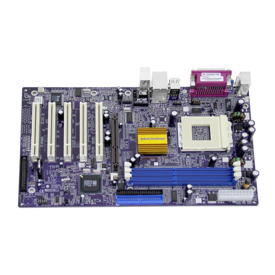
Introducing the Mainboard Thank you for choosing the L7S7A2 mainboard. The L7S7A2 is designed to fit the advanced AMD processors in the 462-pin package. Based on the ATX form factor featuring the SiS746 Northbridge and SiS963/963L Southbridge chipsets. This mainboard provides the standard 133/166MHz front side bus with for high-end business or personal desktop markets. -
Page 6: Checklist
Compare the mainboard’s package contents with the following checklist: Standard Items • One mainboard • One diskette drive ribbon cable (optional) • One IDE drive ribbon cable • One auto-install software support CD • One I/O panel • This user’s manual... -
Page 7: Features
Each slot supports up to 1 GB with a total maximum capacity of 3 GB Graphics The L7S7A2 includes an AGP slot that provides eight times the bandwidth of the original AGP specification. The AGP 3.0 (8xAGP) offers a significant increase in performance along with feature enhancements to AGP2.0. - Page 8 • Two IDE connectors which support four IDE channels and a floppy disk drive interface The L7S7A2 supports Ultra DMA bus mastering with transfer rates of 33/66/100/133 MB/sec. Onboard LAN RTL8201BL is a Fast Ethernet Phyceiver with an MII (Media (optional) Independent Interface)/SNI (Serial Network Interface).
-
Page 9: Choosing A Computer Case
There are many types of computer cases on the market. The mainboard com- plies with the specifications for the ATX system case. Some features on the mainboard are implemented by cabling connectors on the mainboard to indi- cators and switches on the system case. Ensure that your case supports all the features required. - Page 11 Table of Mainboard Components Label Component 1394A-J2 IEEE 1394A header AGP1 Accelerated Graphics Port (supports 1.5V AGP card only) ATX1 Standard 20-pin ATX power connector AUDIO1 Front audio connector BAT1 Three volt realtime clock battery BAKFAN1 Case fan connector 2 CDIN1 Primary CD-in connector CDIN2...
-
Page 12: Installing The Mainboard
Installing the Mainboard Follow these safety precautions when installing the mainboard: • Wear a grounding strap attached to a grounded device to avoid damage from static electricity. • Discharge static electricity by touching the metal case of a safely grounded object before working on the mainboard. •... -
Page 13: Installing The Mainboard In A Case
Refer to the following illustration and instructions for installing the mainboard in a case: This illustration shows an ex- 2. Secure the mainboard with ample of a mainboard being screws where appropriate. installed in a tower-type case: Note: Do not overtighten the screws as this can stress the main- board. -
Page 14: Checking Jumper Settings
Checking Jumper Settings The following illustration shows the location of the mainboard jumpers. Pin 1 is labeled. Jumper Settings Jumper Type Description Setting (default) 1-2: Normal 3-pin Clear CMOS 2-3: Clear CMOS FID JP1 10-pin CPU ratio selector Refer to the table on the next page. Jumper 1 –... -
Page 15: Connecting Case Components
FIDJP1 – Sets the CPU ratio. Refer to the following table. 9-10 Ratio Short — — — — By CPU Open Open Open Open Open 10.5 Open Open Open Open Short Open Open Open Short Open Open Open Open Short Short 12.5 Open... - Page 16 CPUFAN1/CHSFAN1/BAKFAN1 : FAN Power Connectors (optional) Signal Name Function System Ground +12V Power +12V Sense Sensor ATX1: ATX 20-pin Power Connector Signal Name Signal Name +3.3V +3.3V +3.3V -12V Ground Ground PS ON# Ground Ground Ground Ground Ground PWRGD +5VSB +12V SJ1: Single color LED header Signal Name...
-
Page 17: Front Panel Connector
Front Panel Connector The front panel connector (PANEL1) provides a standard set of switch and LED connectors commonly found on ATX or micro-ATX cases. Refer to the table below for information: PANEL1 Signal Function Signal Function Hard disk LED MSG LED [dual color HD_LED_P FP PWR/SLP (positive) -
Page 18: Installing Hardware
Installing the Processor Caution: When installing a CPU heatsink and cooling fan make sure that you DO NOT scratch the mainboard or any of the surface-mount resistors with the clip of the cooling fan. If the clip of the cooling fan scrapes across the mainboard, you may cause serious damage to the mainboard or its components. - Page 19 CPU Installation Procedure The following illustration shows CPU installation components: Note: The pin-1 corner is marked with an arrow Follow these instructions to install the CPU: Pull the CPU socket locking lever away from the socket to unhook it and raise the locking lever to the upright position.
-
Page 20: Installing Memory Modules
Connect the CPU Cooling Fan power cable connector to the CPUFAN connector. Note: CPU fan and heatsink installation procedures may vary with the type of CPU fan/heatsink supplied. The form and size of fan/heatsink may also vary. Installing Memory Modules This mainboard accommodates three 184-pin 2.5V unbuffered Double Data Rate (DDR) SDRAM memory modules. - Page 21 Align the memory module with the slot. The DIMM slots are keyed with notches and the DIMMs are keyed with cutouts so that they can only be in- stalled correctly. Check that the cutouts on the DIMM module edge connector match the notches in the DIMM slot.
-
Page 22: Installing A Hard Disk Drive/Cd-Rom
Installing a Hard Disk Drive/CD-ROM This section describes how to install IDE devices such as a hard disk drive and a CD-ROM drive. About IDE1 and IDE2 Devices Your mainboard has a primary and secondary IDE channel interface (IDE1 and IDE2). -
Page 23: Installing A Floppy Diskette Drive
Disk Auto Detect feature to configure the hard disk drive that you have in- stalled. Installing a CD-ROM/DVD Drive Install the CD-ROM/DVD drive into the drive cage in your system case. Plug the IDE cable into IDE1 (A). If you have already installed an HDD, use the other connec- tor on the IDE cable. -
Page 24: Installing Add-On Cards
Plug a power cable from the case power supply into the power connector on the FDD (C). When you first start up your system, go immediately to the Setup Utility to configure the floppy diskette drives that you have installed. Installing Add-on Cards The slots in this mainboard are designed to hold expansion cards and connect them to the system bus. - Page 25 PCI Slots PCI slots are used to install expansion cards that have the 32-bit PCI interface. AGP Slot The AGP slot is used to install 3D graphics adapter that supports the 8x AGP card which is also backward compatible with 4x AGP card. The slot is keyed to support only the latest 1.5-volt AGP cards.
-
Page 26: Connecting Optional Devices
Connecting Optional Devices Refer to the following for information on connecting the mainboard’s optional devices: AUDIO1: Front Panel Audio header This header allows the user to install auxiliary front-oriented microphone and line-out ports for easier access. Signal Name Function AUD_MIC Front Panel Microphone input signal AUD_GND Ground used by Analog Audio Circuits... - Page 27 USB3: Front panel USB connectors The mainboard has four USB ports installed on the rear edge I/O port array. Additionally, some computer cases have USB ports at the front of the case. If you have this kind of case, use auxiliary USB connector USB3 to connect the front-mounted ports to the mainboard.
- Page 28 1394A_J2: IEEE 1394A header (optional) Use this header to connect to any IEEE 1394A interface. Signal Name Signal Name Cable-power TPA- TPA+ TPB- Chassis GND TPB+ SMI1: System Management Interrupt This connector is for use with SMI hardware interrupt power management. Signal Name Function -EXTSMI...
-
Page 29: Connecting I/O Devices
The backplane of the mainboard has the following I/O ports: PS/2 Mouse Use the upper PS/2 port to connect a PS/2 pointing device. PS/2 Keyboard Use the lower PS/2 port to connect a PS/2 keyboard. LPT1 Use LPT1 to connect printers or other parallel commu- nications devices. -
Page 30: External Connector Color Coding
External Connector Color Coding Many connectors now use standard colors as shown in the table below. Connector Color Audio line-in Light blue Audio line-out Lime Digital monitor/flat panel White IEEE 1394 Grey Microphone Pink MIDI/game Gold Parallel Burgundy PS/2-compatible keyboard Purple PS/2-compatible mouse Green... -
Page 31: Using Bios
Using BIOS The computer uses the latest AMI BIOS with support for Windows Plug and Play. The CMOS chip on the mainboard contains the ROM setup instructions for configuring the mainboard BIOS. The BIOS (Basic Input and Output System) Setup Utility displays the system's configuration status and provides you with options to set system parameters. -
Page 32: Running The Setup Utility
Running the Setup Utility Each time your computer starts, before the operating system loads, a mes- sage appears on the screen that prompts you to “Hit <DEL> if you want to run SETUP”. When you see this message, press the Delete key and the Main menu page of the Setup Utility appears on your monitor. -
Page 33: Using Bios
When you start the Setup Utility, the main menu appears. The main menu of the Setup Utility displays a list of the options that are available. A highlight indicates which option is currently selected. Use the cursor arrow keys to move the highlight to other options. -
Page 34: Advanced Cmos Setup
drive, select the setting CDROM. If you have an ATAPI device with removable media (e.g. a ZIP drive or an LS-120) select Floptical. Advanced CMOS Setup The Advanced CMOS setup is used to control advanced system information such as hardware access and boot settings. Quick Boot (Enabled) If you enable this item, the system starts up more quickly be elimination some of the power on test routines. - Page 35 Hard Disk Access Control (Read-Write) This option specifies the read/write access that is set when booting from a hard disk drive. S.M.A.R.T for Hard Disks (Disabled) Set this option to Enabled to permit the BIOS to use the SMART (System Management and Reporting Technologies) protocol for reporting server sys- tem information over a network.
-
Page 36: Advanced Chipset Setup
Advanced Chipset Setup The Advanced Chipset Setup option is used to change the values of the chip- set registers. These registers control most of the system options in the computer. You should leave the items on this page at their default values, if you change the values incorrectly, you may introduce fatal errors or recurring instability into your system. - Page 37 Interference) generated by the system. Auto Detect DRAM Frequency (Disabled) When set to enable, the BIOS automatically detects the reasonable speed for memory to maintain the system stability. On Board LAN (Enabled) Enables and disables the onboard LAN. LAN Boot ROM Support (Disabled) Use this item to enable and disable the booting from the onboard LAN with a remote boot ROM installed.
-
Page 38: Power Management Setup
Power Management Setup The Power Management Setup Menu option is used to change the values of the chipset registers for system power management. Power Switch Type (On/Off) This option specifies how the power button is used. In the Suspend mode, the hard disk motor is spindled down, the monitor is shut down, and the processor clock is stopped. -
Page 39: Pci / Plug And Play Setup
Resume On RTC Alarm / Date / Hour / Minute / Second The system can be turned off with a software command. If you enable this item, the system can automatically resume at a fixed time based on the sys- tem’s RTC (realtime clock). - Page 40 This section describes configuring the PCI bus system. PCI (Peripheral Com- ponent Interconnect) is a system, which allows I/O devices to operate at speeds nearing CPU’s when they communicate with own special components. All the options describes in this section are important and technical and it is strongly recommended that only experienced users should make any changes to the default settings.
-
Page 41: Peripheral Setup
This option specifies the PCI interrupt used by the secondary IDE channel on the offboard PCI IDE controller. DMA Channel 0/1/3/5/6/7 (PnP) This option allows you to specify the bus type used by each DMA channel. IRQ (PCI/ PnP) This option specifies the bus that the specified IRQ line is used on. They allow you to reserve IRQs for legacy ISA adapter cards and determine if the BIOS should remove an IRQ from the pool of available IRQs passed to devices that are configurable by the system BIOS. - Page 42 USB Function (Enabled) Enable this item if you plan to use the USB ports on this mainboard. USB KB/Mouse/FDD Legacy Support (Enabled) Set this item to enable to support for older keyboard, mouse and legacy de- vices if the USB option is set to enable. Onboard 1394 Device (Enable) Enable this item if you plan to use the onboard 1394 device.
-
Page 43: Hardware Monitor Page
Hardware Monitor Page This section sets some of the parameters for the hardware monitoring function of this mainboard. CPU / System Temperature These items display CPU and system temperature measurement. FANs & Voltage Measurements These items indicate cooling fan speeds in RPM and the various system volt- age measurements. -
Page 44: Change Supervisor/User Password
Change Supervisor/User Password When this function is selected, the following message appears at the center of the screen to assist you in creating a password. ENTER PASSWORD Type the password, up to eight characters, and press <Enter>. The password typed now will clear any previously entered password from CMOS memory. You will be asked to confirm the password. -
Page 45: Auto Configuration With Optimal Settings
Auto Configuration with Optimal Settings If you select this item and press Enter a dialog box appears. If you press Y, and then Enter, the Setup Utility loads a set of fail-safe default values. These default values are not very demanding and they should allow your system to function with most kinds of hardware and memory chips. -
Page 46: Using The Mainboard Software
Using the Mainboard Software The support software CD-ROM that is included in the mainboard package contains all the drivers and utility programs needed to properly run the bun- dled products. Below you can find a brief description of each software program, and the location for your mainboard version. -
Page 47: Running Setup
Setup Tab Setup Click the Setup button to run the software installation program. Select from the menu which software you want to install. Browse The Browse CD button is the standard Windows command that allows you to open Windows Explorer and show the contents of the support CD. -
Page 48: Manual Installation
Note: The following screens are examples only. The screens and driver lists will be different according to the mainboard you are installing. The mainboard identification is located in the upper left-hand corner. Click Next. The following screen appears: Check the box next to the items you want to install. The default options are recommended. -
Page 49: Utility Software Reference
Insert the CD in the CD-ROM drive and locate the PATH.DOC file in the root directory. This file contains the information needed to locate the drivers for your mainboard. Look for the chipset and mainboard model; then browse to the directory and path to begin installing the drivers. - Page 50 MediaRing Talk – Telephony Software To install the MediaRing Talk voice modem software for the built-in modem, go directory \UTILITY\MEDIARING TALK, then MRTALK- SETUP72.EXE to install the application software. Super Voice – Fax/Modem Software To install the Super Voice voice, fax, data communication application for use with the built-in fax/modem, go the directory \UTILITY\SUPER_VOICE, then run PICSHELL.EXE to install the application software.
Need help?
Do you have a question about the L7S7A2 and is the answer not in the manual?
Questions and answers