Table of Contents
Advertisement
Quick Links
Copyright
This publication, including all photographs, illustrations and software, is protected
under international copyright laws, with all rights reserved. Neither this manual, nor
any of the material contained herein, may be reproduced without w ritten consent of
the author.
Version 1.1a
Disclaimer
The information in this document is subject to change without notice. The
manufacturer makes no representations or warranties with respect to the contents
hereof and specifically disclaims any implied w arranties of merchantability or fitness
for any particular purpose. The manufacturer reserves the right to revise this
publication and to make changes from time to time in the content hereof without
obligation of the manufacturer to notify any person of such revision or changes.
Trademark Recognition
Microsoft, MS-DOS and Windows are registered trademarks of Microsoft Corp.
MMX, Pentium, Pentium-II, Pentium-III, Celeron are registered trademarks of Intel
Corporation.
Other product names used in this manual are the properties of their respective owners
and are acknowledged.
Federal Communications Commission (FCC)
This equipment has been tested and found to comply with the limits for a Class B
digital device, pursuant to Part 15 of the FCC Rules. These limits are designed to
provide reasonable protection against harmful interference in a residential installation.
This equipment generates, uses, and can radiate radio frequency energy and, if not
installed and used in accordance with the instructions, may cause harmful interference
to radio communications. However, there is no guarantee that interference will not
occur in a particular installation. If this equipment does cause harmful interference to
radio or television reception, which can be determined by turning the equipment off
and on, the user is encouraged to try to correct the interference by one or more of the
following measures:
−
Reorient or relocate the receiving antenna.
−
Increase the separation between the equipment and the receiver.
−
Connect the equipment onto an outlet on a circuit different from that to which
the receiver is connected.
−
Consult the dealer or an experienced radio/TV technician for help.
Shielded interconnect cables and a shielded AC power cable must be employed with
this equipment to ensure compliance with the pertinent RF emission limits governing
this device. Changes or modifications not expressly approved by the system's
manufacturer could void the user's authority to operate the equipment.
Preface
Advertisement
Table of Contents

Related Manuals for ECS L4S5M


Summary of Contents for ECS L4S5M
- Page 1 Preface Copyright This publication, including all photographs, illustrations and software, is protected under international copyright laws, with all rights reserved. Neither this manual, nor any of the material contained herein, may be reproduced without w ritten consent of the author. Version 1.1a Disclaimer The information in this document is subject to change without notice.
- Page 2 Declaration of Conformity This device complies with part 15 of the FCC rules. Operation is subject to the follow ing conditions: − This device may not cause harmful interference, and − This device must accept any interference received, including interference that may cause undesired operation.
-
Page 3: Table Of Contents
Preface 錯誤! 尚未定義書籤。 Features and Packing List Translations CHAPTER 1 Introducing the Mainboard Introduction......................1 Checklist.........................1 Standard Items ....................1 Features........................2 Choosing a Computer Case................3 Mainboard Components..................4 CHAPTER 2 Installing the Mainboard Safety Precautions....................6 Quick Guide......................6 Installing the Mainboard in a Case..............7 Checking Jumper Settings...................7 Setting Jumpers .................... - Page 4 Advanced BIOS Setup Option ................ 29 Advanced Chipset Features Option..............31 Integrated Peripherals Option................33 Power Management Setup Option..............37 PNP/PCI Configuration Option............... 41 Frequency/Voltage Control................42 Load Fail-Safe Defaults Option ..............43 Load Optimized Defaults Option ..............43 Set Password Option ..................43 Save &...
-
Page 5: Introducing The Mainboard
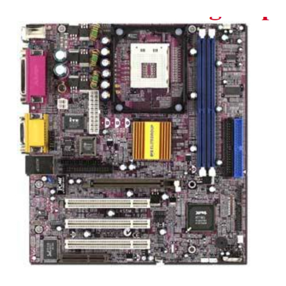
244 mm x 220 mm. The mainboard features a mPGA Socket 478 that accommodates Pentium 4 processors supporting frontside bus (FSB) speeds up to 100 MHz. The L4S5M incorporates the SiS645 chipset which combines support for the new high-bandwidth Double Data Rate (DDR) SDRAM, and the AC 97 audio codec. -
Page 6: Features
2.5V 184-pin slots. Each slot supports up to 1 GB with a total maximum capacity of 2 GB. The L4S5M includes a 4xAGP slot that provides four times the bandwidth of the original AGP specification. AGP technology provides a direct connection between the graphics sub-system and the processor so that the graphics do not have to compete for processor time with other devices on the PCI bus. -
Page 7: Choosing A Computer Case
• Two PS/2 ports for mouse and keyboard • One serial port • One parallel port • One MIDI/game port • Two USB ports • One LAN port • Audio jacks for microphone, line-in and line-out BIOS This mainboard uses Award BIOS that enables users to Firm ware configure many system features including the following: •... -
Page 8: Mainboard Components
RETENTION MODULE LED1 DIMM1 DIMM2 C P U F A N 1 CPUFAN1 LED1 CPU SOCKET ATX2 ATX1 A T X 1 IDE2 IDE1 LAUDIO1 COM2 CDIN2 LMDN1 C O M 2 C D I N 1 C D I N 2 L M D N 1 CDIN1 J P 2... - Page 9 Table of Mainboard Components Label Component AGP1 Accelerated Graphics Port ATX1 Auxiliary power connector for Pentium 4 CPUs ATX2 Power connector BAKFAN1 Case fan connector 2 BAT1 Three volt realtime clock battery CDIN1 Primary CD-in connector CDIN2 Secondary CD-in connector CHSFAN1 Case fan connector 1 CNR1...
-
Page 10: Installing The Mainboard
Installing the Mainboard Follow these safety precautions when installing the mainboard: • Wear a grounding strap attached to a grounded device to avoid damage from static electricity. • Discharge static electricity by touching the metal case of a safely grounded object before working on the mainboard. •... -
Page 11: Installing The Mainboard In A Case
Refer to the following illustration and instructions for installing the mainboard in a case: This illustration shows an 2. Secure the mainboard with example of a mainboard being screws where appropriate. installed in a tower-type case: Note: Do not overtighten the screws as this can stress the mainboard. -
Page 12: Checking Jumper Settings
Checking Jumper Settings The following illustration shows the location of the mainboard jumpers. Pin 1 is labeled. CPUFAN1 LED1 ATX1 COM2 CD IN 2 L M D N 1 C DI N1 FLOPPY1 AGP1 PCI1 L U S B 1 PCI2 PCI3 L S I R 1... -
Page 13: Connecting Case Components
After you have installed the mainboard into a case, you can begin connecting the mainboard components. Refe r to the following: Connect the Pentium CPUFAN1 4 processor auxiliary case power supply CPUFAN1 connector to ATX1. LED1 Connect the standard ATX1 power supply connector to ATX2. -
Page 14: Installing Hardware
Installing the Processor Caution: When installing a CPU heatsink and cooling fan make sure that you DO NOT scratch the mainboard or any of the surface-mount resistors with the clip of the cooling fan. If the clip of the cooling fan scrapes across the mainboard, you may cause serious damage to the mainboard or its components. - Page 15 CPU Installation Procedure The following illustration shows CPU installation components: CPU fan Retention modules Locking lever Pin-1 corner mPGA478 Socket Note: The pin -1 corner is marked with an arrow Follow these instructions to install the CPU: Pull the CPU socket locking lever away from the socket to unhook it and raise the locking lever to the upright position.
- Page 16 Swing the locking lever down and hook it under the latch on CPU fan CPU fan the edge of the socket. power cable Heatsink Snap the four retention legs of Cooling Fan the cooling fan into place (see diagram below). Heatsink Retention Module Swing both lock levers on top of the cooling fan to their opposite sides to...
-
Page 17: Installing Memory Modules
Installing Memory Modules This mainboard accommodates 184-pin 2.5V unbuffered Double Data Rate (DDR) SDRAM memory modules. The memory chips must be standard or registered SDRAM (Synchronous Dynamic Random Access Memory). The memory bus runs at 100 MHz. Installation Procedure The mainboard accommodates two memory modules. -
Page 18: Installing A Hard Disk Drive/Cd-Rom
Installing a Hard Disk Drive/CD-ROM This section describes how to install IDE devices such as a hard disk drive and a CD-ROM drive. About IDE Devices Your mainboard has a primary and secondary IDE channel interface (IDE1 and IDE2). An IDE ribbon cable supporting two IDE devices is bundled with the mainboard. -
Page 19: Installing A Floppy Diskette Drive
Installing a CD-ROM/DVD Drive Install the CD-ROM/DVD drive into the drive cage in your system case. Plug the IDE cable into IDE1 (A). If you have already installed CD-ROM CD-ROM audio an HDD, use the other connector connector on the IDE cable. Note: Ribbon cable connectors are usually keyed so that they can only Colored... -
Page 20: Installing Add-On Cards
Plug the correct connector on the FDD cable for the 5.25-inch or 3.5-inch drive into the FDD connector (B). Plug a power cable from the case power supply into the power connector on the FDD (C). When you first start up your system, go immediately to the Setup Utility to configure the floppy diskette drives that you have installed. - Page 21 Note: For some add-on cards, for example graphics adapters and network adapters, you have to install drivers and software before you can begin using the add-on card.
-
Page 22: Connecting Optional Devices
Connecting Optional Devices Refer to the following for information on connecting the mainboard’s optional devices: COM2 C P U F A N 1 LAUDIO1 L E D 1 ATX1 COM2 CDIN2 LMDN1 CDIN1 LMDN1 J P 2 F L O P P Y 1 A G P 1 P C I 1 LUSB1... - Page 23 LAUDIO1: Front Audio Connector This connector is used to attach to Audio equipment embedded into o r attached to the case. Signal Name Signal Name ALOR ALOL AGND AGND AGND AGND +12V AGND FLOR FLOL AGND LMDN1: Modem-in header Connect a modem add-on card to this header. The cable is bundled with the add-on card.
- Page 24 J3: Power switch This power switch is an alternative connector used for specially designed power connectors. Signal Name +5VSB GROUND POWERON WOL1/WOM: Wake On LAN/Wake On Modem If you have installed a LAN card, use the cable provided with the card to plug into the mainboard WOL1 connector.
- Page 25 SPEAKER1: Internal speaker Connect the internal speaker connector to this header. Signal Name SIGNAL Ground J2: Smart I/O interface header The Smart I/O connector is for use with media storage devices using the LPC interface. Signal Name Signal Name PCICLK VCC3 SERIRQ VCC3...
-
Page 26: Connecting I/O Devices
The backplane of the mainboard has the following I/O ports: Parallel port (LPT1) Game port PS/2 port mouse ports PS/2 Serial port Microphone keyboard COM 1 Line-in Line-out PS/2 Mouse Use the upper PS/2 port to connect a PS/2 pointing device. -
Page 27: External Connector Color Coding
External Connector Color Coding Many connectors now use standard colors as shown in the table below. Connector Color Audio line-in Light blue Audio line-out Lime Digital monitor/flat panel White IEEE 1394 Grey Microphone Pink MIDI/game Gold Parallel Burgundy PS/2-compatible keyboard Purple PS/2-compatible mouse Green... -
Page 28: Using Bios
Using BIOS The computer uses the latest Award BIOS with support for Windows Plug and Play. The CMOS chip on the mainboard contains the ROM setup instructions for configuring the mainboard BIOS. The BIOS (Basic Input and Output System) Setup Utility displays the system's configuration status and provides you with options to set system parameters. -
Page 29: Entering The Setup Utility
Entering the Setup Utility When you power on the system, BIOS enters the Power-On Self Test (POST) routines. POST is a series of built-in diagnostics performed by the BIOS. After the POST routines are completed, the following message appears: Press DEL to enter SETUP Pressing the delete key accesses the BIOS Setup Utility: CMOS Setup Utility –... -
Page 30: Using Bios
If your mainboard has an item called Firmware Write Protect in Advanced BIOS features, disable it. (Firmware Write Protect prevents BIOS from being overwritten.) Create a bootable system disk. (Refer to Windows online help for information on creating a bootable system disk.) Download the Flash Utility and new BIOS file from the manufacturer's Web site. -
Page 31: Standard Cmos Features
Standard CMOS Features This option displays basic information about your system. CMOS Setup Utility – Copyright (C) 1984 – 2001 Award Software Standard CMOS Features Item Help Date (mm:dd:yy) Tue, July 11 2001 Time (hh:mm:ss) 12 : 8 : 59 Menu Level IDE Primary Master Change the day, month,... - Page 32 IDE HDD Auto-Detection Press <Enter> while this item is highlighted to prompt the Setup Utility to automatically detect and configure an IDE device on the IDE channel. Note: If you are setting up a new hard disk drive that supports LBA mode, more than one line will appear in the parameter box.
-
Page 33: Advanced Bios Setup Option
Advanced BIOS Setup Option This option defines advanced information about your system. CMOS Setup Utility – Copyright (C) 1984 – 2001 Award Software Advanced BIOS Features Item Help Anti-Virus Protection [Disabled ] CPU L1 & L2 Cache [Enabled] Menu Level Quick Power On Self Test [Enabled] First Boot Device... - Page 34 Swap Floppy Drive (Disabled) If you have two floppy diskette drives in your system, this item allows you to swap the assigned drive letters so that drive A becomes drive B, and drive B becomes drive A. Boot Up Floppy Seek (Disabled) If this item is enabled, it checks the size of the floppy disk drives at start-up time.
-
Page 35: Advanced Chipset Features Option
Report No FDD For WIN95 (Yes) If you are running a system with no floppy drive and using Windows 95, select Yes for this item to ensure compatibility with the Windows 95 logo certification. Otherwise, select No. Small Logo (EPA) Show (Disabled) Enables or disables the display of the EPA logo during boot. - Page 36 System Performance (Normal Mode) This is the DRAM auto configuration option, which can be set to Safe Mode, Normal Mode, Fast Mode or Ultra Mode. CAS Latency Setting (2.5T) Enables you to select the CAS latency time in HCLKs of 2, 2.5, or 3. The value is set at the factory depending on the DRAM installed.
-
Page 37: Integrated Peripherals Option
Integrated Peripherals Option These options display items that define the operation of peripheral components on the system's input/output ports. CMOS Setup Utility – Copyright (C) 1984 – 2001 Award Software Integrated Peripherals Item Help SIS OnChip IDE Device [Press Enter] SIS OnChip PCI Device [Press Enter] Menu Level... - Page 38 IDE Primary/Secondary Master/Slave PIO (Auto) Each IDE channel supports a master device and a slave device. These four items let you assign which kind of PIO (Programmed Input/Output) is used by IDE devices. Choose Auto to let the system auto detect which PIO mode is best, or select a PIO mode from 0-4.
- Page 39 Onboard SuperIO Device Scroll to this item and press <Enter> to view the following screen: CMOS Setup Utility – Copyright (C) 1984 – 2001 Award Software Onboard SuperIO Device Item Help Onboard FDC Controller [Enabled] Onboard Serial Port 1 [3F8/IRQ4] Menu Level Onboard Serial Port 2 [2F8/IRQ3]...
- Page 40 UR2 Duplex Mode (Half) This field is available when UART 2 Mode is set to either ASKIR or IrDA. This item enables you to determine the infrared function of the onboard infrared chip. The options are Full and Half (default). Full-duplex means that you can transmit and send information simultaneously.
-
Page 41: Power Management Setup Option
SC Port Address (Disabled) The smart card reader needs a 16-byte fixed I/O address to access data. You may need an optional module to be able to use this function. When this item is set, the following item becomes available: •... - Page 42 Power Management Timeouts The power-saving modes can be controlled by timeouts. If the system is inactive for a time, the timeouts begin counting. If the inactivity continues so that the timeout period elapses, the system enters a power-saving mode. If any item in the list of Reload Global Timer Events is Enabled, then any activity on that item will reset the timeout counters to zero.
- Page 43 Video Off Option (Susp, Stby --> Off) This option defines if the video is powered down when the system is put into suspend mode. Video Off Method (DPMS Supported) This item defines how the video is powered down to save power. This item is set to DPMS (Display Power Management Software) by default.
- Page 44 PM Wake Up Events Scroll to this item and press <Enter> to view the following screen: CMOS Setup Utility – Copyright (C) 1984 – 2000 Award Software PM Wake Up Events Item Help IRQ [3-7, 9-15], NMI [Enabled ] IRQ 8 Break suspend [Disabled ] Menu Level Ring/WOL/WOM PowerUp Contl...
-
Page 45: Pnp/Pci Configuration Option
PNP/PCI Configuration Option These options configure how PnP (Plug and Play) and PCI expansion cards operate in your system. Both the ISA and PCI buses on the Mainboard use system IRQs (Interrupt ReQuests) and DMAs (Direct Memory Access). You must set up the IRQ and DMA assignments correctly through the PnP/PCI Configurations Setup utility for the mainboard to work properly. -
Page 46: Frequency/Voltage Control
the PCI interface of your system. PC Health Status Option On mainboards that support hardware monitoring, this item lets you monitor the parameters for critical voltages, critical temperatures, and fan speeds. CMOS Setup Utility – Copyright (C) 1984 – 2001 Award Software PC Health Status Item Help Shutdown Temperature... -
Page 47: Load Fail-Safe Defaults Option
↑ ↓ → ← : Move Enter : Select +/-/PU/PD:Value: F10: Save ESC: Exit F1:General Help F5:Previous Values F6:Fail-Safe Defaults F7:Optimized Defaults CPU Clock Ratio (0 X) Use the CPU Host/SDRAM/PCI Clock to set the frontside bus frequency for the installed processor (usually 133 MHz, 100 MHz or 66 MHz). Then use CPU Clock Ratio Jumpless to set a multiple. -
Page 48: Save & Exit Setup Option
Enter Password: If you are installing a new password, type in the password. You cannot use more than eight characters o r numbers. The Set Password item differentiates between upper and lower case characters. Press <Enter> after you have typed in the password. If you are deleting a password that is already installed press <Enter>... -
Page 49: Using The Mainboard Software
Using the Mainboard Software The support software CD-ROM that is included in the mainboard package contains all the drivers and utility programs needed to properly run the bundled products. Below you can find a brief description of each software program, and the location for your mainboard version. More information on some programs is available in a README file, located in the same directory as the software. -
Page 50: Running Setup
Setup Click the Setup button to run the software installation program. Select from the menu which software you want to install. Browse CD The Browse CD button is the standard Windows command that allows you to open Windows Explorer and show the contents of the support CD. Before installing the software from Windows Explorer, look for a file named README.TXT, INSTALL.TXT or something similar. - Page 51 Click Next. The following screen appears: Check the items you want to install. The default options are recommended. Click Next to run the Installation Wizard. An item installation screen appears: Follow the instructions on the screen to install the items. Drivers and software are automatically installed in sequence.
-
Page 52: Manual Installation
Insert the CD in the CD-ROM drive and locate the PATH.DOC file in the root directory. This file contains the information needed to locate the drivers for your mainboard. Look for the chipset and mainboard model; then browse to the directory and path to begin installing the drivers. -
Page 53: Mediaring Talk - Telephony Software
MediaRing Talk – Telephony Software To install the MediaRing Talk voice modem software for the built-in modem, run MRTALK-SETUP72.EXE from the following directory: \UTILITY\MEDIARING TALK Super Voice – Fax/Modem Software To install the Super Voice voice, fax, data communication application for use with the built-in fax/modem, run PICSHELL.EXE from the following directory: \UTILITY\SUPER VOICE CD Ghost...
Need help?
Do you have a question about the L4S5M and is the answer not in the manual?
Questions and answers