Table of Contents
Advertisement
Quick Links
Copyright
This publication, including all photographs, illustrations and software, is protected un-
der international copyright laws, with all rights reserved. Neither this manual, nor any
of the material contained herein, may be reproduced without written consent of the au-
thor.
Version 2.0
Disclaimer
The information in this document is subject to change without notice. The manufac-
turer makes no representations or warranties with respect to the contents hereof and
specifically disclaims any implied warranties of merchantability or fitness for any par-
ticular purpose. The manufacturer reserves the right to revise this publication and to
make changes from time to time in the content hereof without obligation of the manu-
facturer to notify any person of such revision or changes.
Trademark Recognition
Microsoft, MS-DOS and Windows are registered trademarks of Microsoft Corp.
MMX, Pentium, Pentium-II, Pentium-III, Celeron are registered trademarks of Intel
Corporation.
Other product names used in this manual are the properties of their respective owners
and are acknowledged.
Federal Communications Commission (FCC)
This equipment has been tested and found to comply with the limits for a Class B digi-
tal device, pursuant to Part 15 of the FCC Rules. These limits are designed to provide
reasonable protection against harmful interference in a residential installation. This
equipment generates, uses, and can radiate radio frequency energy and, if not in-
stalled and used in accordance with the instructions, may cause harmful interference
to radio communications. However, there is no guarantee that interference will not oc-
cur in a particular installation. If this equipment does cause harmful interference to
radio or television reception, which can be determined by turning the equipment off
and on, the user is encouraged to try to correct the interference by one or more of the
following measures:
−
Reorient or relocate the receiving antenna.
−
Increase the separation between the equipment and the receiver.
−
Connect the equipment onto an outlet on a circuit different from that to which
the receiver is connected.
−
Consult the dealer or an experienced radio/TV technician for help.
Shielded interconnect cables and a shielded AC power cable must be employed with
this equipment to ensure compliance with the pertinent RF emission limits governing
this device. Changes or modifications not expressly approved by the system's manu-
facturer could void the user's authority to operate the equipment.
Preface
Advertisement
Table of Contents

Related Manuals for ECS L7VMM2


Summary of Contents for ECS L7VMM2
- Page 1 Preface Copyright This publication, including all photographs, illustrations and software, is protected un- der international copyright laws, with all rights reserved. Neither this manual, nor any of the material contained herein, may be reproduced without written consent of the au- thor.
- Page 2 Declaration of Conformity This device complies with part 15 of the FCC rules. Operation is subject to the follow- ing conditions: − This device may not cause harmful interference, and − This device must accept any interference received, including interference that may cause undesired operation.
-
Page 3: Table Of Contents
Preface CHAPTER 1 Introducing the Motherboard Introduction ....................1 Checklist .....................1 Standard Items ....................1 Features .....................2 Choosing a Computer Case ...............4 Motherboard Components ................5 CHAPTER 2 Installing the Motherboard Safety Precautions..................7 Quick Guide ....................7 Installing the Motherboard in a Case ............8 Checking Jumper Settings ................8 Setting Jumpers .................... - Page 4 Power Management Setup ................43 PNP/PCI Configurations................48 PC Health Status.................... 49 Frequency/Voltage Control................50 Load Fail-Safe Defaults................. 51 Load Optimized Defaults................51 Set Supervisor/User Password............... 51 Save & Exit Setup ..................52 Exit Without Saving ..................52 CHAPTER 4 Using the Motherboard Software About the Software CD-ROM ..............53 Auto-installing under Windows 98/ME/2000/XP ........53...
-
Page 5: Introducing The Motherboard
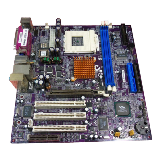
AC97 link compatible sound system and full System Management Bus (SMBus) interface. The L7VMM2 is equipped with advanced full set of I/O ports, such as dual channel IDE interfaces, a floppy controller, a high-speed serial port, a VGA port, an EPP/ECP capable bi-directional parallel port connector, four USB... -
Page 6: Features
Further features include support for four analog line-level stereo inputs. Expansion L7VMM2 has three 32-bit PCI slots, an AGP slot and CNR Options (Communications and Networking Riser) slot. The L7VMM2 supports Ultra DMA bus mastering with transfer... - Page 7 Onboard LAN The Realtek’s RTL8201BL is a Fast Ethernet Phyceiver with MII interface to MAC chip. It provides the following features: • Support MII interface • Support 10/100Mbps operation • Support half/full duplex operation • 3.3V operation with 5V signal •...
-
Page 8: Choosing A Computer Case
There are many types of computer cases on the market. The motherboard complies with the specifications for the Micro ATX system case. Some fea- tures on the motherboard are implemented by cabling connectors on the motherboard to indicators and switches on the system case. Ensure that your case supports all the features required. - Page 10 Table of Motherboard Components Label Component 1394AJ1/1394AJ2* IEEE 1394A header AGP1 Accelerated Graphics Port ATX1 Standard 20-pin ATX power connector AUDIO1 Front audio connector BAT1 Three volt realtime clock battery CASFAN1 Case fan connector Primary CD-in connector CNR1 Communications Networking Riser slot CPU SOCKET Socket A for AMD Athlon/Duron CPUs CPUFAN1...
-
Page 11: Installing The Motherboard
Installing the Motherboard Follow these safety precautions when installing the motherboard: • Wear a grounding strap attached to a grounded device to avoid damage from static electricity. • Discharge static electricity by touching the metal case of a safely grounded object before working on the motherboard. •... -
Page 12: Installing The Motherboard In A Case
Refer to the following illustration and instructions for installing the mother- board in a case: This illustration shows an ex- 2. Secure the mainboard with ample of a motherboard being screws where appropriate. installed in a tower-type case: Note: Do not overtighten the screws as this can stress the moth- erboard. -
Page 13: Checking Jumper Settings
Checking Jumper Settings The following illustration shows the location of the motherboard jumpers. Pin 1 is labeled. Jumper Settings Jumper Type Description Setting (default) 3-pin Clear CMOS 1-2: Normal 2-3: Clear CMOS 3-pin CPU Frequency 1-2: 100Mhz 2-3: 133Mhz JP1 – Use this jumper to clear the contents of the CMOS memory. -
Page 14: Connecting Case Components
Connecting Case Components After you have installed the motherboard into a case, you can begin connect- ing the motherboard components. Refer to the following: Connect the CPU cooling fan cable to CPUFAN1. Connect the case cooling fan connector to CASFAN1. Connect the case speaker cable to SPEAKER1. - Page 15 SJI: Single-color LED header Signal Name ACPI LED ACPI LED 5VSB ACPI LED function: S4/S5 Light Blinking Blinking Dark LSJI: Single color LED header (optional for OEM customers only) Signal Name 5VSB SUSLED-Y ACPI LED function: LSJ1 S4/S5 Dark Dark Light Dark...
-
Page 16: Front Panel Connector
Front Panel Connector The front panel connector (PANEL1) provides a standard set of switch and LED connectors commonly found on ATX or micro-ATX cases. Refer to the table below for information: Signal Name Function HD_LED_P Hard disk LED (positive) FP PWR/SLP MSG LED [dual color or single color (+)] HD_LED_N Hard disk active LED (negative) -
Page 17: Installing Hardware
Installing the Processor Caution: When installing a CPU heatsink and cooling fan make sure that you DO NOT scratch the motherboard or any of the surface-mount resis- tors with the clip of the cooling fan. If the clip of the cooling fan scrapes across the motherboard, you may cause serious damage to the mother- board or its components. - Page 18 CPU Installation Procedure The following illustration shows CPU installation components: Note: The pin-1 corner is marked with an arrow Follow these instructions to install the CPU: Pull the CPU socket locking lever away from the socket to unhook it and raise the locking lever to the upright position.
- Page 19 Connect the CPU Cooling Fan power cable connector to the CPUFAN connector. Note: CPU fan and heatsink installation procedures may vary with the type of CPU fan/heatsink supplied. The form and size of fan/heatsink may also vary.
-
Page 20: Installing Memory Modules
Installing Memory Modules This motherboard accommodates two 184-pin 2.5V unbuffered Double Data Rate (DDR) SDRAM memory modules. The memory chips must be standard SDRAM (Synchronous Dynamic Random Access Memory). The memory bus can run up to 133 MHz. When you installed DDR266 memory modules, the memory bus can run up to 133 MHz. -
Page 21: Installing A Hard Disk Drive/Cd-Rom
Install the DIMM module into the slot and press it firmly down until it seats correctly. The slot latches are levered upwards and latch on to the edges of the DIMM. Install any remaining DIMM modules. Installing a Hard Disk Drive/CD-ROM This section describes how to install IDE devices such as a hard disk drive and a CD-ROM drive. - Page 22 Plug an IDE cable connector into the hard disk drive IDE connector (B). It doesn't matter which connector on the cable you use. Plug a power cable from the case power supply into the power connector on the hard disk drive (C). When you first start up your system, the BIOS should automatically detect your hard disk drive.
-
Page 23: Installing A Floppy Diskette Drive
Installing a Floppy Diskette Drive The motherboard has a floppy diskette drive (FDD) interface and ships with a diskette drive ribbon cable that supports one or two floppy diskette drives. You can install a 5.25-inch drive and a 3.5-inch drive with various capacities. The floppy diskette drive cable has one type of connector for a 5.25-inch drive and another type of connector for a 3.5-inch drive. -
Page 24: Installing Add-On Cards
Installing Add-on Cards The slots in this motherboard are designed to hold expansion cards and con- nect them to the system bus. Expansion slots are a means of adding or enhancing the motherboard’s features and capabilities. With these efficient facilities, you can increase the motherboard’s capabilities by adding hardware which performs tasks that are not part of the basic system. - Page 25 Follow these instructions to install an add-on card: Remove a blanking plate from the system case corresponding to the slot you are going to use. Install the edge connector of the add-on card into the expansion slot. Ensure that the edge con- nector is correctly seated in the slot.
-
Page 26: Connecting Optional Devices
Connecting Optional Devices Refer to the following for information on connecting the motherboard’s op- tional devices: AUDIO1: Front Panel Audio header This header allows the user to install auxiliary front-oriented microphone and line-out ports for easier access. Signal Name Function AUD_MIC Front Panel Microphone input signal AUD_GND... - Page 27 USB3: Front Panel USB connector The motherboard has four USB ports installed on the rear edge I/O port array. Additionally, some computer cases have USB ports at the front of the case. If you have this kind of case, use auxiliary USB connector USB3 to connect the front-mounted ports to the motherboard.
- Page 28 SPDIF1: SPDIF out header This is an optional header that provides an S/PDIF (Sony/Philips Digital Inter- face) output to digital multimedia device through optical fiber or coaxial connector. Signal Name Function SPDIF SPDIF digital output +5VA 5V analog power Not connected Ground 1394AJ1/1394AJ2: IEEE 1394A header (optional)
- Page 29 USBCR1: USB Card Reader connector (optional) This connector is for connecting internal USB card reader. You can use a card reader to read or transfer files and digital images to your computer. Signal Name Function USBVCC2 +5V dual USB2- Data signal port 2- USB2+ Data signal port 2+ Ground...
-
Page 30: Connecting I/O Devices
The backplane of the motherboard has the following I/O ports: PS/2 Mouse Use the upper PS/2 port to connect a PS/2 point- ing device. PS/2 Keyboard Use the lower PS/2 port to connect a PS/2 key- board. LPT1 Use LPT1 to connect printers or other parallel communications devices. -
Page 31: External Connector Color Coding
External Connector Color Coding Many connectors now use standard colors as shown in the table below. Connector Color Audio line-in Light blue Audio line-out Lime Digital monitor/flat panel White IEEE 1394 Grey Microphone Pink MIDI/game Gold Parallel Burgundy PS/2-compatible keyboard Purple PS/2-compatible mouse Green... -
Page 32: Using Bios
Using BIOS The computer uses the latest Award BIOS with support for Windows Plug and Play. The CMOS chip on the motherboard contains the ROM setup instruc- tions for configuring the motherboard BIOS. The BIOS (Basic Input and Output System) Setup Utility displays the system's configuration status and provides you with options to set system parameters. -
Page 33: Entering The Setup Utility
Entering the Setup Utility When you power on the system, BIOS enters the Power-On Self Test (POST) routines. POST is a series of built-in diagnostics performed by the BIOS. After the POST routines are completed, the following message appears: Press DEL to enter SETUP Pressing the delete key accesses the BIOS Setup Utility: Phoenix –... -
Page 34: Using Bios
If your motherboard has an item called Firmware Write Protect in Advanced BIOS features, disable it. (Firmware Write Protect prevents BIOS from being overwritten.) Create a bootable system disk. (Refer to Windows online help for infor- mation on creating a bootable system disk.) Download the Flash Utility and new BIOS file from the manufacturer's Web site. -
Page 35: Standard Cmos Feature
Standard CMOS Feature This option displays basic information about your system. Phoenix – AwardBIOS CMOS Setup Utility Standard CMOS Feature Item Help Date (mm:dd:yy) Tue, Jun 11 2002 Time (hh:mm:ss) 15 : 6 : 23 Menu Level IDE Primary Master Change the day, month, IDE Primary Slave [None]... - Page 36 IDE HDD Auto-Detection Press <Enter> while this item is highlighted to prompt the Setup Utility to automatically detect and configure an IDE device on the IDE channel. Note: If you are setting up a new hard disk drive that supports LBA mode, more than one line will appear in the parameter box.
-
Page 37: Advanced Bios Features
Advanced BIOS Features This option defines advanced information about your system. Phoenix – AwardBIOS CMOS Setup Utility Advanced BIOS Features Item Help Anti-Virus Protection [Disabled] CPU Internal Cache [Enabled] Menu Level External Cache [Enabled] CPU L2 Cache ECC Checking [Enabled] Allows you to choose Processor Number Feature [Enabled]... - Page 38 Processor Number Feature (Enabled) Some new processors are installed with a unique processor number. This number may be used for verification in Internet transactions and e-commerce. If you prefer not to use or distribute the unique processor number, disable this item to suppress the processor number.
-
Page 39: Advanced Chipset Features
Security Option (Setup) If you have installed password protection, this item defines if the password is required at system start up, or if it is only required when a user tries to enter the Setup Utility. APIC Mode (Enabled) This item allows you to enable APIC (Advanced Programmable Interrupt Con- troller) functionality. - Page 40 iar with the technical specifications of your system hardware. If you change the values incorrectly, you may introduce fatal errors or recurring instability into your system. Phoenix – AwardBIOS CMOS Setup Utility Advanced Chipset Features Item Help DRAM Clock/Drive Control [Press Enter] AGP &...
- Page 41 DRAM Timing (By SPD) Set this to the default value to enable the system to automatically set the SDRAM timing by SPD (Serial Presence Detect). SPD is an EEPROM chip on the DIMM module that stores information about the memory chips it contains, including size, speed, voltage, row and column addresses, and manufacturer.
- Page 42 Phoenix – AwardBIOS CMOS Setup Utility AGP & P2P Bridge Control Item Help AGP Aperture Size [128MB] AGP Driving Control [Auto] Menu Level AGP Driving Value AGP Fast Write [Disabled] AGP Master 1 WS Write [Disabled] AGP Master 1 WS Read [Disabled]] ↑...
-
Page 43: Integrated Peripherals
Phoenix – AwardBIOS CMOS Setup Utility CPU & PCI Bridge Control Item Help PCI1 Master 0 WS Write [Enabled] PCI2 Master 0 WS Write [Enabled] Menu Level PCI1 Post Write [Enabled] PCI2 Post Write [Enabled] PCI Delay Transaction [Disabled] ↑ ↓ → ← : Move Enter : Select +/-/PU/PD:Value: F10: Save ESC: Exit... - Page 44 nents on the system's input/output ports. Phoenix – AwardBIOS CMOS Setup Utility Integrated Peripherals Item Help VIA OnChip IDE Device [Press Enter] VIA OnChip PCI Device [Press Enter] Menu Level Super I/O Device [Press Enter] Init Display First [PCI Slot] OnChip USB Controller [All Enabled] USB Keyboard Support...
- Page 45 Primary/Secondary Master/Slave UDMA (Auto) Each IDE channel supports a master device and a slave device. This mother- board supports UltraDMA technology, which provides faster access to IDE devices. If you install a device that supports UltraDMA, change the appropriate item on this list to Auto.
- Page 46 SuperIO Device Scroll to this item and press <Enter> to view the following screen: Phoenix – AwardBIOS CMOS Setup Utility SuperIO Device Item Help Onboard FDC Controller [Enabled] Onboard Serial Port 1 [3F8/IRQ4] Menu Level Onboard Serial Port 2 [Disabled] UART Mode Select [Normal] UR2 Duplex Mode...
-
Page 47: Power Management Setup
Parallel Port Mode (ECP) Enables you to set the data transfer protocol for your parallel port. There are four options: SPP (Standard Parallel Port), EPP (Enhanced Parallel Port), ECP (Extended Capabilities Port) and ECP+EPP. SPP allows data output only. Extended Capabilities Port (ECP) and Enhanced Parallel Port (EPP) are bi-directional modes, allowing both data input and output. - Page 48 the video, suspending to RAM, and software power down that allows the sys- tem to be automatically resumed by certain events. Power Management Timeouts The power-saving modes can be controlled by timeouts. If the system is inac- tive for a time, the timeouts begin counting. If the inactivity continues so that the timeout period elapses, the system enters a power-saving mode.
- Page 49 (STR), the suspend mode is a suspend to RAM, i.e., the system shuts down with the exception of a refresh current to the system memory. Power Management Option (User Define) This item acts like a master switch for the power-saving modes and hard disk timeouts.
- Page 50 Phoenix – AwardBIOS CMOS Setup Utility IRQ/Event Activity Detect Item Help PS2KB Wakeup Select [Hot key] PS2MS Wakeup from S1-S3 [Disabled] Menu Level PS2KB WakeUp from S1-S3 [Disabled] USB WakeUp from S1-S3 [Disabled] [OFF] LPT & COM [LPT/COM] HDD & FDD [ON] PCI Master [OFF]...
- Page 51 ing mode. Wake Up On LAN/Ring (Disabled) Use this item to enable LAN or modem activity to wakeup the system from a power saving mode. RTC Alarm Resume (Disabled) When set to Enabled, additional fields become available and you can set the date (day of the month), hour, minute and second to turn on your system.
-
Page 52: Pnp/Pci Configurations
PNP/PCI Configurations These options configure how PnP (Plug and Play) and PCI expansion cards oper- ate in your system. Both the ISA and PCI buses on the Motherboard use system IRQs (Interrupt ReQuests) and DMAs (Direct Memory Access). You must set up the IRQ and DMA assignments correctly through the PnP/PCI Configurations Setup utility for the motherboard to work properly. -
Page 53: Pc Health Status
expansion card. Use the second item Reserved Memory Length to set the amount of reserved memory. Press <Esc> to close the Memory Resources sub-menu. PCI/VGA Palette Snoop (Disabled) This item is designed to overcome some problems that can be caused by some non-standard VGA cards. -
Page 54: Frequency/Voltage Control
Frequency/Voltage Control This item enables you to set the clock speed and system bus for your system. The clock speed and system bus are determined by the kind of processor you have installed in your system. Phoenix – AwardBIOS CMOS Setup Utility Frequency/Voltage Control Item Help Auto Detect PCI/DIMM Clk... -
Page 55: Load Fail-Safe Defaults
Load Fail-Safe Defaults This option opens a dialog box that lets you install fail-safe defaults for all ap- propriate items in the Setup Utility: Press <Y> and then <Enter> to install the defaults. Press <N> and then <En- ter> to not install the defaults. The fail-safe defaults place no great demands on the system and are generally stable. -
Page 56: Save & Exit Setup
Save & Exit Setup Highlight this item and press <Enter> to save the changes that you have made in the Setup Utility and exit the Setup Utility. When the Save and Exit dialog box appears, press <Y> to save and exit, or press <N> to return to the main menu: Exit Without Saving Highlight this item and press <Enter>... -
Page 57: Using The Motherboard Software
Using the Motherboard Software The support software CD-ROM that is included in the motherboard package contains all the drivers and utility programs needed to properly run the bun- dled products. Below you can find a brief description of each software program, and the location for your motherboard version. -
Page 58: Running Setup
Setup Tab Setup Click the Setup button to run the software installation program. Select from the menu which software you want to install. Browse The Browse CD button is the standard Windows command that allows you to open Windows Explorer and show the contents of the support CD. - Page 59 The motherboard identification is located in the upper left-hand corner. Click Next. The following screen appears: Check the box next to the items you want to install. The default options are recommended. Click Next run the Installation Wizard. An item installation screen ap- pears: Follow the instructions on the screen to install the items.
-
Page 60: Manual Installation
Insert the CD in the CD-ROM drive and locate the PATH.DOC file in the root directory. This file contains the information needed to locate the drivers for your motherboard. Look for the chipset and motherboard model; then browse to the directory and path to begin installing the drivers.
Need help?
Do you have a question about the L7VMM2 and is the answer not in the manual?
Questions and answers