
Related Manuals for MIB Flowmax 242i


Summary of Contents for MIB Flowmax 242i
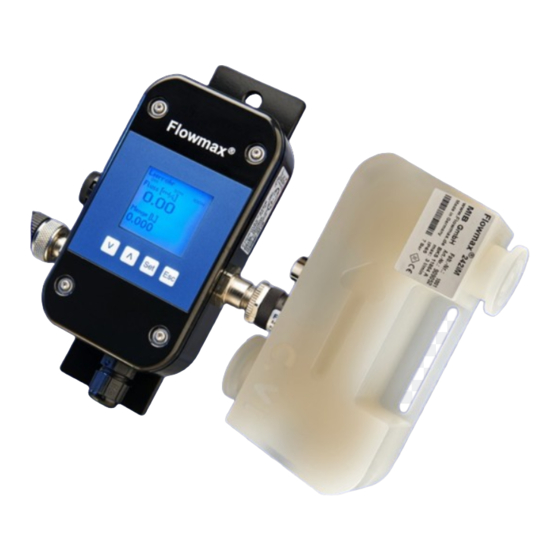
- Page 1 Flowmax 242i BA 010E/FM242i/08.22 Valid starting from Hardware V 2.1 Ultrasonic flow Software V 1.29 metering / dosing device Operating manual...
-
Page 2: General Safety Instructions
NOTICE! is used to lead users to helpful NOTICE! information not related to personal injury. Intended use The flow meter Flowmax 242i may only be used for measuring the flow of pure, homogeneous liquids. The volume flow meter Flowmax 242i is built operationally safe in ... -
Page 3: Table Of Contents
Flowmax 242i Tablet of contents Tablet of contents General safety instructions ......................2 Tablet of contents ......................... 3 Table of figures ..........................5 Planning information ......................6 1.1 Areas of application ..........................6 1.2 Measuring principle ..........................6 1.3 Operational safety ..........................7 Assembly and installation..................... - Page 4 Exchange of flow meter ...................... 30 Technical specifications ..................... 31 5.1 Dimensions and weight ........................31 5.2 Technical specifications ........................32 5.3 Possible error text Flowmax 242i ....................... 33 Accessories ......................... 33 Shipment ..........................33 Appendix ............................. 34 M I B...
-
Page 5: Table Of Figures
Figure 1: Presentation of the principle of ultrasonic flow measuring ..........6 Figure 2: Installation position of Flowmax 242i................7 Figure 3: Mounting examples for Flowmax 242i ................8 Figure 4: Mounting possibilities ....................... 9 Figure 5: Fixing Flowmax 242i ......................9 Figure 6: Pin code: Connection plug socket for 5-pin version ........ -
Page 6: Planning Information
242i 1. Planning information 1.1 Areas of application The flow measurement device in the Flowmax 242i designed to measure dynamic flow in pipes and tubes. This flow meter is suitable for liquids only. The Flowmax 242i is used in Bio-processing applications ... -
Page 7: Operational Safety
2. Assembly and installation 2.1 Installation instructions The housing of the Flowmax 242i has an arrow, symbolizing the flow direction of measurement. The flow meter has to be installed in a way so that the flow-through is in the same direction as the arrow symbol. -
Page 8: Assembly Of The Flow Meter
Assembly and installation Flowmax 242i When using pumps, Flowmax 242i must be installed in flow direction on the pressure side, on order to ensure sufficient pressure. The maximum pressure rating of Flowmax 242i has to be considered. Do not exceed the maximum pressure allowance for of the Flowmax 242i (see section 5.2 Technical specifications). -
Page 9: Figure 4: Mounting Possibilities
Residual liquid may remain inside the device if flow meter is mounted horizontally. Vibrations or mechanical forces may decrease measuring accuracy. So if there is due to vibration or mechanical movements it is necessary to fix Flowmax 242i additionally, the instrument can be fixed on the lateral slot. -
Page 10: Electrical Wiring
Always shut off or disconnect electrical power at service panel and lock switch or breaker and tag to prevent energizing electrical power during work or while Flowmax 242i is not assembled and installed. The electrical connection between the electronics and the measuring pipe can be disconnected under voltage. -
Page 11: Figure 7: Pin Code: Connection Plug / Socket For 8-Pin Version
Flowmax 242i Assembly and installation 8-pin plug with 1-wire communication: Figure 7: Pin code: Connection plug socket for 8-pin version Connector cable pin configuration defined by manufacturer. The outlets may be re-programmed for specific applications. Function Description 24 VDC Voltage supply: 18 ... -
Page 12: Commissioning
IMPORTANT! 3. Commissioning NOTE: If Flowmax 242i is used for a fluid other than water the "basic trim" has to be carried out during commissioning. Therefore the device has absolutely be filled with medium. The basic trim can be done on the device display. During the adjustment the medium may not flow as it affects the function 3.1 Operation... -
Page 13: Display And User Menu
The default password for Flowmax 242i is 41414. The user level will remain active for 30 minutes after the last press on any button. 200 seconds after the last key press, the device skips the menu and returns to the display mode, which does not apply to the menu items diagnostic and dosing. - Page 14 Commissioning Flowmax 242i M I B...
-
Page 15: Figure 9: Menu Structure
Flowmax 242i Commissioning Figure 9: Menu structure M I B... -
Page 16: Functionalities Of Flow Meter And Default Settings
Spanish, French and German. 3.2.2 Dosing The Flowmax 242i can be configured for manually dosing by choosing the dosing function via the user display. The Volume “Dosing Quantity“ and the “Dosing Time“ are freely adjustable. The dosing time is intended as a safeguard against unintentional overspill. -
Page 17: Media
In the sub menu “Set Offset” it is possible to set the actual offset of the flow meter. Use this function only when Flowmax 242i is completely filled with liquid, and there is no flow. If the offset is set while flow is present or when the pipe is empty it will cause an offset drift what results in a faulty measurement. -
Page 18: Basic Trim
3.2.3.4 Basic Trim The “Basic Trim” function insures that the flowmeter is conforming to the media NOTICE! specific characteristics. To execute this function, Flowmax 242i runs a self- diagnostic function which optimizes all important parameters. This process lasts approximately 1 minute. -
Page 19: General Settings
Flowmax 242i Commissioning 3.2.4 General Settings 3.2.4.1 Reset Counter The volume counter of Flowmax 242i can be reset. Example of operation see appendix. IMPORTANT! Once reset, counter values cannot be restored. After a reset the counter works IMPORTANT! normally. -
Page 20: Lower Limit
The pulse value determines the flow volumes for which an output pulse will be emitted. Choose a configuration which will neither exceed the maximum output frequency of the Flowmax 242i (10kHz) nor the maximum input frequency of the control. If the maximum frequency is exceeded the Flowmax 242i will not output pulses correctly. -
Page 21: Total Counter
Flowmax 242i Commissioning 3.2.4.7 Total Counter The Total Counter can be displayed in the menu. The unit is fixed to m³. This NOTICE! counter is unidirectional and can therefore differ from the daily counters. The Total Counter can not be set to zero! 3.2.4.8 Counter The daily counters is the one that appears by default in the display. -
Page 22: Display
Flowmax 242i 3.2.5 Display 3.2.5.1 Units Flowmax 242i is able to show actual flow or the volume in different units. Setting range: ml/s + l, l/h + l, l/min + m³, Gal/min +Gal, l/min + l Default setting: ml/s + l Example: ml/s + l Here, the flow appears in the unit "ml / s"... -
Page 23: Analog Output Qa
Flowmax 242i Commissioning 3.2.6 Analog Output QA 3.2.6.1 Function The Analog Output is an active current output with 0-20mA or 4-20mA. It can be adjusted via the display menu or FlowCon 200i. Figure 13: The current output is active Setting range: 0 …... -
Page 24: Figure 14: Characteristic Curve 0
Commissioning Flowmax 242i Characteristic curves analog output 0 … 20mA For the following graphic “min Range” is used for 0% and “max Range” is used for 100%. Current output 0 ... 20mA Value [%] Value Current [mA] Smaller 0% 0% (min Range) Between 0% and 100% Linear interpolation from 0 ... -
Page 25: Filter
When this function via the menu (see Section 3.1.1 Fig 12. Menu structure NOTICE! Flowmax 242i with analog output QA - Output value) is selected and the function PID controller was not ordered, the output will be set on “flow”. -
Page 26: Digital Outputs Q1 And Q2 (Q2 Only Available With 8-Pin Plug)
Commissioning Flowmax 242i Temperature measurement for the analog output Via the analog output the measured temperature is output. The temperature sensor is not wetted. It is used to calculate the extent of the measuring channel. The sensor is influenced by the ambient temperature. The temperature value will become sluggish, because it measures the plastic - Temperature inside the sensor pocket. -
Page 27: Figure 17: Connecting Digital Output To Relay
IMPORTANT! IMPORTANT! Inductive load on the digital outputs without an installed diode may cause damage on the Flowmax 42i electronics. Example 1: Flowmax 242i via npn, external relay Figure 17: Connecting digital output to relay M I B... -
Page 28: Digital Input I1 (Only Available With 8-Pin Plug)
3.2.8 Digital Input I1 (only available with 8-pin plug) Flowmax 242i has a digital input that is programmable for the following functions: dosing input, set offset, creeping suppression inactive and reset counter. In order to start a dosing process, 24V DC power is required. -
Page 29: Testing Flow
When everything has been checked, switch on power. After 30 minutes with power running the measuring device reaches the maximum accuracy. The meter reaches the optimum operating state after 30 minutes. See 3.Commissioning. Flowmax 242i is operational! M I B... -
Page 30: Exchange Of Flow Meter
If the device requires a configuration change, the display and programming unit FlowCon 200i may be required (see section 6. Accessories). Repair, hazardous substances Before sending the flow meter Flowmax 242i for repair, the following precautions must be taken: Clean all process chemicals from the device. Fully rinse the flow ... -
Page 31: Technical Specifications
Flowmax 242i Technical specifications 5. Technical specifications 5.1 Dimensions and weight Dimension Flowmax 242iM (Measuring Channel) Nominal diameter Height Depth Width Weight [mm] [mm] [mm] DN 3 / 5 / 7 DN 10 Dimension Flowmax 242iE (Electronics) Height Depth Width Weight [mm] [mm] [mm]... -
Page 32: Technical Specifications
Connection to the measuring pipe via a green cable, length 0,5, 1,5 or 2,0m. The measuring system Flowmax 242i meets the general EMC immunity requirements according to CE, EN 61000-6-3, EN 61000-4-2, EN 61000-4-3, EN 61000-4-4, EN 61000-4-5, EN 61000-4-6. It is in conformity with the requirements of the EC directives and has the CE label. -
Page 33: Possible Error Text Flowmax 242I
However, the measurement still works. 6. Accessories Flowmax connection socket Flowmax connection socket is used to power and connect Flowmax 242i to an external control unit. Ordercode 507321 (Socket 5 pins) Ordercode... -
Page 34: Appendix
Appendix Flowmax 242i Appendix Examples of operation: Enter Password Display picture Password 4 x Λ 40000 X0000 Λ X1000 XX000 4 x Λ XX400 XXX00 Λ XXX10 XXXX0 4 x Λ XXXX4 Set Offset Use this function only when Flowmax 242iM is completely filled with liquid, and there is no flow. - Page 35 Flowmax 242i Appendix 1-point correction With the 1-point correction, the meter is calibrated to an operating point. For this purpose, a typical volume for the application is filled into a container and the weight is determined with a scale. Attention: subtract the weight of the container. With inclusion of the density of the medium, the volume (volume = mass / density) is obtained.
- Page 36 Appendix Flowmax 242i Display rotate 90° Dosing Media General Adjustment Display Analog Output QA Media General Adjustment Display Analog Output QA Digital Output Q1 Display Units 2 x V Display Rotate Display Display Rotate Display 0° 3 x V Display Rotate Display 90°...
- Page 37 Flowmax 242i Appendix M I B...
- Page 38 Appendix Flowmax 242i M I B...
- Page 39 MIB GmbH Messtechnik und Industrieberatung Bahnhofstr. 35 D-79206 Breisach Tel. 0049 / (0)7667 / 20 777 90 Fax 0049 / (0)7667 / 20 777 99 E-Mail: info@mib-gmbh.com Internet: www.flowmax.de...
Need help?
Do you have a question about the Flowmax 242i and is the answer not in the manual?
Questions and answers