Table of Contents
Advertisement
Quick Links
Advertisement
Table of Contents

Related Manuals for EVGA Z75 SLI


Summary of Contents for EVGA Z75 SLI
-
Page 1: User Guide
User Guide EVGA Z75 SLI Motherboard... -
Page 2: Table Of Contents
EVGA Z75 Motherboard Table of Contents User Guide ........................1 EVGA Z75 SLI ....................... 1 Motherboard ........................1 Before You Begin… ...................... 4 Parts NOT in the Kit......................4 Intentions of the Kit ......................5 Motherboard ........................6 Motherboard Specifications ....................6 Unpacking and Parts Descriptions ................ - Page 3 Post Port Debug LED and LED Status Indicators ............... 23 Post Port Debug LED ....................23 LED Status Indicators ....................23 Installing Drivers and Software ..................24 Windows 7/Vista/XP ......................25 Driver Installation ....................... 25 Appendix A. POST Codes...................25 EVGA Glossary of Terms ....................30 Compliance Information ....................33...
-
Page 4: Before You Begin
EVGA Z75 Motherboard Before You Begin… Thank you for purchasing the EVGA Z75 SLI Motherboard. This board is based off of the new Intel Z75 chipset with native support for SATA III/6G and USB 3.0 for the performance you demand, delivered when you need it. -
Page 5: Intentions Of The Kit
EVGA Z75 Motherboard Intentions of the Kit This kit provides you with the motherboard and all connecting cables necessary to install the motherboard into a PC case. If you are building a PC, you will use most of the cables provided in the kit. If however, you are replacing a motherboard, you will not need many of the cables. -
Page 6: Motherboard
EVGA Z75 Motherboard EVGA Z75 SLI Motherboard Motherboard Specifications Size ATX form factor of 12 inches x 9.6 inches Microprocessor support Intel Socket 1155 Processor Operating systems: Supports Windows 7/Vista/XP 32 and 64 bit Contains Intel Z75 chipset ... -
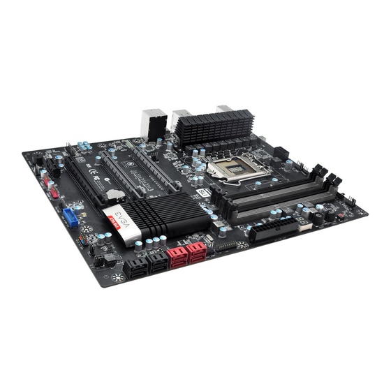
Page 7: Unpacking And Parts Descriptions
PCI-E x8/x16 slots Unpacking and 7 Parts Descriptions Unpacking The EVGA Z75 SLI Motherboard comes with all the necessary cables for adding a motherboard to a system case. If replacing a motherboard, you may not need many of these cables. -
Page 8: Equipment
EVGA Z75 Motherboard Equipment The following accessories are included with the EVGA Z75 SLI Motherboard: The EVGA Z75 SLI Motherboard This PCI-E motherboard contains the Intel Z75 chipset and is SLI-ready. 1 - Visual Guide Helps to quickly and visually guide you through the hardware installation of the motherboard. - Page 9 EVGA Z75 Motherboard 1 - Installation CD Contains drivers that are needed to setup the motherboard. 1 – User Manual Contains Information needed to properly install and configure your EVGA Motherboard.
-
Page 10: Hardware Installation
EVGA Z75 Motherboard Hardware Installation This section will guide you through the installation of the motherboard. The topics covered in this section are: Preparing the motherboard Installing the CPU Installing the CPU fan Installing the memory ... -
Page 11: Preparing The Motherboard
EVGA Z75 Motherboard Preparing the Motherboard Installing the CPU Be very careful when handling the CPU. Hold the processor only by the edges and do not touch the bottom of the processor. Use the following procedure to install the CPU onto the motherboard: Unhook the socket lever by pushing down and away from the socket. -
Page 12: Installing The Cpu Fan
EVGA Z75 Motherboard Align the notches in the processor with the notches on the socket. Lower the processor straight down into the socket without tilting or sliding it into the socket. Note: Make sure the CPU is fully seated and level in the socket. -
Page 13: Installing System Memory (Dimms)
EVGA Z75 Motherboard Installing System Memory (DIMMs) Your new motherboard has four 240-pin slots for DDR3 memory. These slots support 1GB, 2GB and 4GB DDR3 DIMMs. There must be at least one memory slot populated to ensure normal operation. Use the following the recommendations for installing memory. -
Page 14: Installing The I/O Shield
EVGA Z75 Motherboard Use the following procedure to install the I/O shield and secure the motherboard into the chassis. Note: Be sure that the CPU fan assembly has enough clearance for the system case covers to lock into place and for the expansion cards. Also make sure the CPU Fan assembly is aligned with the vents on the covers. -
Page 15: Securing The Motherboard Into A System Case
EVGA Z75 Motherboard Securing the Motherboard into a System Case Most system cases have a base with mounting studs or spacers to allow the motherboard to be secured to the chassis and help to prevent short circuits. If there are studs that do not align with a mounting hole on the motherboard, it is recommended that you remove that stud to prevent the possibility of a short circuit. -
Page 16: 24-Pin Atx Power (Pwr_24)
EVGA Z75 Motherboard Expansion slots CMOS Clear Button 24-pin ATX Power (PWR_24) is the main power supply connector located along the edge of the PWR_24 board next to the DIMM slots. Make sure that the power supply cable and pins are properly aligned with the connector on the motherboard. -
Page 17: 8-Pin Atx 12V Power (Atx_Pwr_8P)
EVGA Z75 Motherboard 8-pin ATX 12V Power ( ATX_PWR_8P) , the 8-pin ATX 12V power connection, is used to provide power to the CPU. Align the pins to the connector and press firmly until seated. +12V BIOS Select Jumper The BIOS Select Jumper is located at the bottom left of the board right next to the front panel header. -
Page 18: Connecting Internal Headers
EVGA Z75 Motherboard Connecting Internal Headers Front Panel Header The front panel header on this motherboard is one connector used to connect the following four cables. (see Table 2 for pin definitions): PWRLED Attach the front panel power LED cable to these two pins of the connector. -
Page 19: Usb Headers
EVGA Z75 Motherboard USB Headers This motherboard contains six (4) USB 2.0 ports that are exposed on the rear panel of the chassis. The motherboard also contains two 10- pin internal header connectors onboard that can be used to connect an optional external bracket containing up to four (4) USB 2.0 ports. -
Page 20: Audio
EVGA Z75 Motherboard Audio The audio connector supports HD audio standard and provides two kinds of audio output choices: the Front Audio and the Rear Audio. The Front Audio supports re-tasking function. Table 4. Front Audio Connector Connector Signal PORT1_L... -
Page 21: Pci-E X1 Slots
EVGA Z75 Motherboard PCI-E x1 Slots There are PCI-E x1 slots that are designed to accommodate less bandwidth- intensive cards, such as a modem, sound or LAN card. PCI-E x16/x8 Slots These PCI-E slots are reserved for Graphics Cards and PCI-E x1, x4, x8 and x16 devices. -
Page 22: Onboard Buttons
EVGA Z75 Motherboard Onboard Buttons These onboard buttons include RESET, POWER and Clear CMOS. These functions allow you to easily reset the system, turn on/off the system, or clear the CMOS. Clear CMOS Button The motherboard uses the CMOS RAM to store all the set parameters. -
Page 23: Post Port Debug Led And Led Status Indicators
EVGA Z75 Motherboard Post Port Debug LED and LED Status Indicators Post Port Debug LED Provides two-digit POST codes to show why the system may be failing to boot. It is useful during troubleshooting situations. This Debug LED will also display current CPU socket temperatures after the system has fully booted into the Operating System. -
Page 24: Installing Drivers And Software
Windows 7, Vista and XP both 32 and 64 Bit. The kit comes with a CD that contains utilities, drivers, and additional software. The CD that has been shipped with the EVGA Z75 SLI Motherboard contains the following software and drivers: Chipset Drivers ... -
Page 25: Windows 7/Vista/Xp
If the CD does not run, go to My Computer and click on the CD to open. Appendix A. POST Codes This section provides the AMI POST Codes (Table 6) for the EVGA Z75 SLI Motherboard during system boot up. The POST Codes are displayed on the Debug LED readout located directly onboard the motherboard. - Page 26 EVGA Z75 Motherboard OEM initialization after microcode loading Cache initialization Reserved for future AMI SEC error codes Microcode not found Microcode not loaded PEI Core is started Pre-memory CPU initialization is started Pre-memory North Bridge initialization is started Pre-memory South Bridge initialization is started OEM pre-memory initialization codes Memory initialization.
- Page 27 EVGA Z75 Motherboard incompatible memory speed Memory initialization error. SPD reading has failed Memory initialization error. Invalid memory size or memory modules do not match. Memory initialization error. No usable memory detected Unspecified memory initialization error. Memory not installed Invalid CPU type or Speed...
- Page 28 EVGA Z75 Motherboard DXE Core is started NVRAM initialization Installation of the South Bridge Runtime Services CPU DXE initialization is started PCI host bridge initialization North Bridge DXE initialization is started North Bridge DXE SMM initialization is started North Bridge DXE initialization (North Bridge...
- Page 29 EVGA Z75 Motherboard IDE Detect IDE Enable SCSI initialization is started SCSI Reset SCSI Detect SCSI Enable Setup Verifying Password Start of Setup Reserved for ASL (see ASL Status Codes section below) Setup Input Wait Reserved for ASL (see ASL Status Codes section...
-
Page 30: Evga Glossary Of Terms
EVGA Z75 Motherboard EVGA Glossary of Terms 1337 – This is reserved for EVGA level elite AC – Alternating Current ACPI - Advanced Configuration and Power Interface AFR – Alternate Frame Rendering APIC - Advanced Programmable Interrupt Controller ACPI – Advanced Configuration and Power Interface BCLK –... - Page 31 EVGA Z75 Motherboard FSB – Front Side Bus FTW – For The Win! GHz – Gigahertz GPU – Graphics Processing Unit HDD - Hard Disk Drive HDMI - High-Definition Multimedia Interface HDR – High Dynamic Range Lighting HPET - High Precision Event Timer HT –...
- Page 32 EVGA Z75 Motherboard OEM - Original Equipment Manufacturer PATA - Parallel Advanced Technology Attachment PCB - Printed Circuit Board PCI - Peripheral Component Interconnect PCIe - Peripheral Component Interconnect Express PCI-x - Peripheral Component Interconnect Extended POST – Power on Self Test PWM –...
-
Page 33: Compliance Information
Original Purchaser. Upon termination, for any reason, all copies of Software and materials must be immediately returned to EVGA and the Original Purchaser shall be liable to EVGA.com CORP for any and all damages suffered as a result of the violation or default.
Need help?
Do you have a question about the Z75 SLI and is the answer not in the manual?
Questions and answers