
Related Manuals for EVGA Z490 DARK


Summary of Contents for EVGA Z490 DARK
- Page 1 EVGA Z490 DARK (131-CL-E499) User Guide EVGA Z490 DARK Specs and Initial Installation - 1 -...
-
Page 2: Table Of Contents
Motherboard Specifications ....................- 6 - Unpacking and Parts Descriptions ..................- 8 - EVGA Z490 DARK Motherboard LED reference ............. - 10 - EVGA Z490 DARK Motherboard Component Legend ............. - 14 - PCIe Slot Breakdown ......................- 27 - M.2 / U.2 Slot Breakdown .................... - Page 3 Multifunction LED indicator .................... - 153 - POST Beep codes ......................- 155 - POST Port Debug LED ....................- 156 - POST Codes ......................- 157 - EVGA Glossary of Terms ....................- 162 - Compliance Information ..................- 165 - - 3 -...
-
Page 4: Before You Begin
8 smart fan headers, and many more premium features. If you’ve been holding out for a serious motherboard to upgrade, the time is at hand. Lastly, a motherboard is only as good as its BIOS, and the EVGA Z490 DARK features EVGA’s newest UEFI/BIOS GUI with a focus on overclocking and functionality in a lean, straightforward package. -
Page 5: Parts Not In The Kit
Monitor (Optional) Optical Drive EVGA assumes you have purchased all the necessary parts needed to allow for proper system functionality. For a full list of supported CPUs on this motherboard, please visit www.evga.com/support/motherboard Intentions of the Kit... -
Page 6: Motherboard Specifications
EVGA Z490 DARK (131-CL-E499) Motherboard Specifications Size: EATX form-factor of 11.99 inches x 10.89 inches (304.5x276.6mm) Microprocessor support: Intel Socket 1200 Processor ® Operating Systems: Supports Windows 10 64bit System Memory support: Supports up to 64GB Dual-Channel DDR4 up to 4800MHz+ (OC) USB 2.0 Ports:... - Page 7 Display Output: Mini-DisplayPort Onboard Audio: Realtek ALC1220 High Definition Audio + EVGA NU Audio Supports 7.1 Channel audio with Optical S/PDIF Out EVGA NU Audio via the FP Audio header Power Functions: Supports ACPI (Advanced Configuration and Power Interface)
-
Page 8: Unpacking And Parts Descriptions
EVGA Z490 DARK (131-CL-E499) Unpacking and Parts Descriptions The following accessories are included with the EVGA Z490 DARK Motherboard: - 8 -... - Page 9 EVGA Z490 DARK (131-CL-E499) - 9 -...
-
Page 10: Evga Z490 Dark Motherboard Led Reference
EVGA Z490 DARK (131-CL-E499) EVGA Z490 DARK Motherboard LED reference The EVGA Z490 DARK Motherboard has several LEDs indicating power, connectivity, and activity. Below is the location of the LEDs and their function. - 10 -... - Page 11 EVGA Z490 DARK (131-CL-E499) LED Legend M.2 Key-E Enabled VCCST Status M.2 Key-M PM1 Enabled Multi-function POST indicator VCCSTG Status U.2 PU1 Status Memory DIMM 2 Status VCCIO_1_2 Status U.2 PU1 Enabled Memory DIMM 1 Status Power Button PE2 Status...
- Page 12 EVGA Z490 DARK (131-CL-E499) 7. VCORE status a. WHITE: Voltage present (Does not mean PSU is outputting in-spec, only that this specific voltage is detected) 8. VDIMM status a. WHITE: Voltage present (Does not mean PSU is outputting in-spec, only that this specific voltage is detected) 9.
- Page 13 EVGA Z490 DARK (131-CL-E499) 20. BIOS3 Active LED a. WHITE: Active BIOS Chip (only 1 will be lit at a time) 21. SW Slow Mode ON a. RED: Slow Mode switch has been set to enabled 22. PCIe Status for PE1. The LED stays off when PE1 is disabled or unpopulated.
-
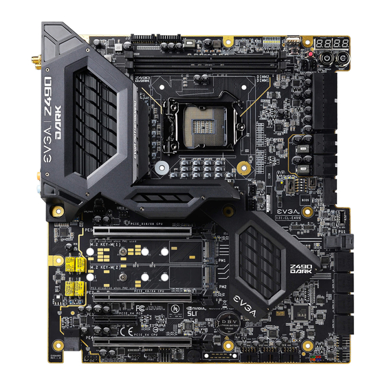
Page 14: Evga Z490 Dark Motherboard Component Legend
EVGA Z490 DARK (131-CL-E499) EVGA Z490 DARK Motherboard Component Legend The EVGA Z490 DARK Motherboard with the Intel Z490 and PCH Chipset. ® Figure 1 shows the motherboard and Figure 2 shows the back panel connectors FIGURE 1. Z490 DARK Motherboard Layout... - Page 15 EVGA Z490 DARK (131-CL-E499) Component Legend CPU Socket LGA1200 PCIe Slot x16/x8 BIOS Selector Switch Intel Z490 PCH PCIe Slot x8/x4 CMOS Battery PWM Fan Headers (2 amp) PCIe Slot x4 PCIe Disable Switches PWM/DC Fan Headers (2 amp) PCIe Slot x4 (x16 Mechanical)
- Page 16 EVGA Z490 DARK (131-CL-E499) Figure 2. Chassis Rear Panel Connectors Intel i225V Activity LED Status Description Speed/Link LED Status Description No Data Transmission Orange 2.5Gbps data rate Blinking (Green) Data Transmission Green 1 Gbps data rate 10/100 Mbps data rate or No Link...
- Page 17 EVGA Z490 DARK (131-CL-E499) Component Legend Descriptions 1. CPU Socket 1200 This is the interface for the Central Processing Unit (CPU), and supports 10 Gen. Intel Core i3, i5, i7 and i9 models compatible with the Intel LGA1200 ® Socket, based on Comet Lake-S architecture.
- Page 18 EVGA Z490 DARK (131-CL-E499) 6. 24-pin ATX power connector The main power for the motherboard is located on the right side of the board and parallel to the PCB; this is also described as a “90 degree / right-angle” connector (See Page 41 for more specifics to the connector itself, and associated wiring/pinouts).
- Page 19 EVGA Z490 DARK (131-CL-E499) 10. ASMedia SATA 6Gbit/s Ports This is a secondary SATA controller, the ASM1061 is a 2-port SATA3/6 Gbit/s controller with legacy support for older operating systems. This is included largely for benchmarking and overclocking with very specific programs, such as Super Pi, 3DMark, PCMark, etc.
- Page 20 EVGA Z490 DARK (131-CL-E499) 14. PCIe Slot x16/x8* PCIe x16/x8 slots are primarily used for video cards. These full-length slots will provide 8 or 16 lanes of bandwidth to a full-size card, and are backwards- compatible with x8, x4, and x1-length cards.
- Page 21 EVGA Z490 DARK (131-CL-E499) 19. Reset Button This is an onboard system reset button, and may be used in place of, or in conjunction with, a front panel system reset button wired to the board. Benching systems, or test benches before final assembly, are best served by using the onboard power because it removes the need to wire a Power/Reset button or cross posts with a screwdriver, which is a semi-common practice.
- Page 22 USB, auxiliary ports that mount in the card slots, and certain devices that directly connect to the header. The USB 3.2 Gen2 Header on the Z490 DARK is a shielded USB 3.2 Gen2 Header and supports up to 10Gb/s with USB 3.2 Gen2.
- Page 23 USB2.0 header and uses the standard “HD Audio” jack. Some chassis may have two cables: HD Audio, and one labeled AC’97 – an AC’97 cable is not compatible with this header on the Z490 DARK. 26. Front Panel Connectors The Front panel connectors are the four main chassis connections.
- Page 24 EVGA Z490 DARK (131-CL-E499) 30. ProbeIt Header J3 The ProbeIt header is a means of live monitoring several different system voltages in real-time with a multimeter. One terminal needs to connect to a ground wire and the other to the specific voltage you want to monitor.
- Page 25 2A will trigger overcurrent protection and lock at 2A. This header allows for far more flexible options to configure your RGB lighting via software-based control within Windows via EVGA ELEET X1, and supports up to 125 LEDs. Please see Page 45 for header specifics, and Page 139 for control options in ELEET X1.
- Page 26 EVGA Z490 DARK (131-CL-E499) Card Slots The Z490 DARK features three x16 PCIe slots, one x4 PCIe slot, two Socket 3 Key-M M.2 110mm slots (PM1/PM2) (backwards compatible with Key-M 80mm, 60mm, and 42mm), and a vertical Socket 1 Key-E M.2 (Contains the WiFi module).
-
Page 27: Pcie Slot Breakdown
EVGA Z490 DARK (131-CL-E499) PCIe Slot Breakdown PCIe Lane Distribution (All Socket 1200 processors are 16 lanes.) PE1 – x16 (Gen3, x16 lanes from CPU, x8 shared with PE2) PE2 – x8 (Gen3, x8 lanes from CPU, x4 shared with PE4) ... -
Page 28: Preparing The Motherboard
Preparing the Motherboard Installing the CPU Note: EVGA strongly recommends that you completely disconnect AC power from your power supply prior to changing your CPU. This ensures the motherboard will use the correct startup procedure for all onboard devices. If AC power is not disconnected, the replacement is still supported, but may require additional reboots to boot successfully. -
Page 29: Installing The Cpu Cooling Device
EVGA Z490 DARK (131-CL-E499) 3. Align the notches on the CPU to the notches in the socket, and lower the processor straight down into the socket. Note: The gold triangle key on the CPU should match the triangle key on the load plate. -
Page 30: Installing System Memory
EVGA Z490 DARK (131-CL-E499) Installing System Memory Your Z490 DARK has (2) 288-pin slots for DDR4 memory. These slots support 4GB, 8GB, 16GB, and 32GB DDR4 Unbuffered non-ECC DIMMs. There must be at least one memory slot populated for the board to boot and operate. -
Page 31: Installing The I/O Shield
EVGA Z490 DARK (131-CL-E499) Installing the I/O Shield The motherboard kit comes with an I/O shield that is used to block internal components from dust and foreign objects, while also promoting correct airflow within the chassis. Before installing the motherboard, install the I/O shield from the inside of the chassis. -
Page 32: Securing The Motherboard Into A System Case
EVGA Z490 DARK (131-CL-E499) Securing the Motherboard into a System Case Most system cases require installation of standoffs into the chassis to allow the motherboard to be mounted to the chassis and prevent short circuits. If there are any studs that do not align with a motherboard mounting hole, we recommend that you remove that standoff to prevent the possibility of a short circuit. - Page 33 EVGA Z490 DARK (131-CL-E499) 1. All safe locations to secure the board to a standoff are circled in blue. 2. Keep in mind that when the screws are installed, but not fully tightened, the motherboard should have 1-2mm of movement; this can help when mounting cards or tight-fits with other components.
-
Page 34: Installing M.2 Devices
SSDs. Next add one thermal pad – included with the Z490 DARK accessories – to the outlined area to the right. 2. After adding the thermal pad, the motherboard will look like the image below. This thermal pad will assist with cooling your M.2 Key-M device. - Page 35 EVGA Z490 DARK (131-CL-E499) 3. Insert the M.2 device at a slight angle of approximately 45 degrees to the board. This will allow the contacts (colloquially called “Gold Fingers”) to seat completely into the slot. If the device is fully seated,...
- Page 36 EVGA Z490 DARK (131-CL-E499) Incorrect installation Example: *NOTE* This is one of the most common examples of an incorrect installation of an M.2 device. Do not intentionally attempt this, or complete your installation with this example. Doing so could cause damage to the device or the M.2 port.
-
Page 37: Tested Cpu And Memory
EVGA Z490 DARK (131-CL-E499) Tested CPU and Memory Core Count Frequency PCI-E Lanes Comet Lake-S Core ™ i9 10900KF 10 Cores +HT 3.70 GHz Core ™ i9 10900K 10 Cores + HT 3.70 GHz Core ™ i9 10900F 10 Cores + HT 2.80 GHz... -
Page 38: Tested M.2 Key-M
EVGA Z490 DARK (131-CL-E499) Tested M.2 Key-M PCIE INTERFACE ADATA ASX8000NP-256GM-C 256G M.2 PCIE Samsung MZ-VKV512 950 PRO Samsung MZ-V6P512 960 PRO Samsung MZ-VPV2560 256G SM951 NVME Samsung MZ-HPU128T/004 128G XP941 Samsung MZ-HPV1280 128G SM951 Samsung MZ-V6E250 250G 960EVO Samsung... -
Page 39: Tested M.2 Key-E
EVGA Z490 DARK (131-CL-E499) Tested U.2 Tested M.2 Key-E - 39 -... -
Page 40: Connecting Cables
Connecting Cables Note: the following images do not necessarily represent the physical orientation of their respective headers on the EVGA Z490 DARK. Rather, these graphical representations are designed to provide a basic physical footprint and the cable pinouts for each component. - Page 41 Firmly plug the power supply cable into the connector and make sure it is secure. The Z490 DARK motherboard uses a right-angle 24pin ATX connector. 6-pin PCIe The 6-pin PCIe connector present on the motherboard provides additional power to the PCIe slots, rather than pulling it all from the 24-pin main power.
- Page 42 EVGA Z490 DARK (131-CL-E499) EPS 8-pin 12V Power (PWR , the 8-pin ATX 12V power connection(s), is used to provide EPS PWR 8P power to the CPU. Align the pins to the connector and press firmly until seated. The secondary EPS, is optional for improved overclocking. Please remember to make sure that the tab on the EPS socket is aligned with the release clip on the cable.
- Page 43 EVGA Z490 DARK (131-CL-E499) Front Panel Header The front panel header on this motherboard is used to connect the following four cables: PWRLED Attach the front panel power LED cable to these two pins of the connector. The Power LED indicates the system’s status. When the system is powered on, the LED will be on.
- Page 44 EVGA Z490 DARK (131-CL-E499) Fan Header This motherboard only has 4-pin fan headers, which are backwards compatible with 3-pin fan connectors. CPU1 and CPU2 controls fans via PWM. The remaining headers control fans by either PWM or DC controls. The headers have an absolute safe power limit of 2 Amp @ 12 Volts (24 Watts).
- Page 45 12V RGB Header. This header supports up to a maximum of 2 Amps @ 5 Volts (10 Watts) or up to 125 LEDs. This will add control options through EVGA ELEET X1 for controlling RGB LEDs. - 45 -...
- Page 46 This header and pinout is also shared with the RGB LED header, which also supports up to 2 Amps @ 12 Volts (24 Watts). This will add control options through EVGA ELEET X1 for controlling RGB LED’s. - 46 -...
- Page 47 This motherboard contains USB 3.2 Gen2 and 3.2 Gen1 ports that are exposed on the rear panel of the chassis. The Z490 DARK contains 1x 20pin internal header, which can support 1 USB3.2 Gen2 Type-C front-panel connector or device. - 47 -...
- Page 48 EVGA Z490 DARK (131-CL-E499) The motherboard contains 1x 19-pin internal header connectors onboard that can be used to connect an optional external bracket or device containing up to two (2) USB 3.2 Gen1 ports. Please note that these headers are often referred to as USB 3.0 internal ...
- Page 49 (4) USB 2.0 ports. The Z490 DARK also features an onboard USB 2.0 port header, near the power/reset buttons. This header has a specific purpose – to allow you to flash the BIOS without an installed CPU using the included USB flash drive.
- Page 50 Front panel audio supports HD Audio for stereo/gaming headphones or 2.1 speakers, and a Mic. The EVGA Z490 DARK front panel audio connector supports the use of EVGA NU Audio when headphones or a headset are connected. - 50 -...
- Page 51 EVGA Z490 DARK (131-CL-E499) Drive Headers (SATA/ U.2) SATA 3/6G is the current standard for HDD/SSD/Optical interface. These cables are the data interconnect for the motherboard. Your HDD/SSD/Optical interface will still require a separate power connection from your power supply.
-
Page 52: Onboard Buttons
EVGA Z490 DARK (131-CL-E499) Onboard Buttons These onboard buttons include RESET, POWER and Clear CMOS. These functions allow you to easily turn on/off the system, reset the system or clear the CMOS. Clear CMOS Button The motherboard uses CMOS RAM to store set parameters. -
Page 53: First Boot
EVGA Z490 DARK (131-CL-E499) First Boot BIOS Update When you power on the system for the first time (or after a BIOS update/reset) it may take a little longer than expected, and follow with a warning message on the screen reading “BIOS checksum error”. - Page 54 EVGA Z490 DARK (131-CL-E499) HDD/SSD/M.2/U.2 Setup Next, click “Boot” from the menu list at the top. “Boot Option #1” should show the device that you intend to install your operating system. If you are using a standard SSD/HDD connected to a SATA port, but the device is not present in the Boot Option #1 menu, scroll down to “UEFI Hard...
-
Page 55: Ssd, Pcie Ssd, And Nvme Ssd Installation Steps
EVGA Z490 DARK (131-CL-E499) M.2 SSD, PCIe SSD, and NVMe SSD Installation steps M.2 is a very fast card bus that can use multiple connecter types to connect many types of devices, such as WiFi or SSDs, in a very small and power efficient package. M.2 devices can be connected via an M.2 card slot or through PCIe by using an M.2 to PCIe adapter. - Page 56 EVGA Z490 DARK (131-CL-E499) 3. Once in BIOS/UEFI, navigate to the “BOOT” section. Then go down to the “CSM Configuration” heading and press enter, or click on it with your mouse. a. For Windows 10: Set “Launch Storage OpROM Policy” to “UEFI”.
-
Page 57: Internal Raid Controller
EVGA Z490 DARK (131-CL-E499) Internal RAID Controller This section introduces RAID, RAID levels, and the basics of the controller integrated into the PCH. It covers the basics of what RAID does, how RAID works, and why you may or may not want to use RAID. - Page 58 EVGA Z490 DARK (131-CL-E499) its quality, and many other factors; but the number should give you a ballpark estimate on what to expect as a final capacity once formatted. Please see below for examples of what to expect when you build an array of each type.
- Page 59 EVGA Z490 DARK (131-CL-E499) one drive fails, the array fails. It MAY be possible to recover the data but that usually requires a data recovery service, which is not guaranteed and is usually very expensive. RAID0 is typically only limited by the controller; however, you will get severely diminishing performance returns after 4 drives.
- Page 60 EVGA Z490 DARK (131-CL-E499) RAID 0 (4 Drive) P-DRIVE1 P-DRIVE2 P-DRIVE3 P-DRIVE4 P-DRIVE1 P-DRIVE2 P-DRIVE3 P-DRIVE4 DATA-A DATA-B DATA-C DATA-D DATA-A DATA-B DATA-C DATA-D DATA-ABCD DATA-ABCD P-DRIVE1 P-DRIVE2 P-DRIVE3 P-DRIVE4 P-DRIVE1 P-DRIVE2 P-DRIVE3 P-DRIVE4 DATA-A DATA-B DATA-C DATA-D DATA-A DATA-B...
- Page 61 EVGA Z490 DARK (131-CL-E499) The Bad- RAID1 is not a storage capacity-friendly array, because the capacity will be limited to 1 drive. o Due to the capacity available on modern drive solutions, this issue may not be as significant as it once was.
- Page 62 EVGA Z490 DARK (131-CL-E499) Similar to RAID1, or any other current type of array with fault tolerance, a RAID5 array is still usable even while it is experiencing a missing or failed drive resulting in the array functioning in a degraded state. Performance will suffer in a degraded state until the missing drive is replaced and the software rebuild process is completed.
- Page 63 EVGA Z490 DARK (131-CL-E499) L-DRIVE = ≃ 3TB RAID 5 (4 Drive) P-DRIVE1 P-DRIVE2 P-DRIVE3 P-DRIVE4 P-DRIVE1 P-DRIVE2 P-DRIVE3 P-DRIVE4 P-DRIVE1 P-DRIVE2 P-DRIVE3 P-DRIVE4 DATA-A DATA-B DATA-C DATA-A DATA-A DATA-B DATA-C DATA-A DATA-A DATA-B DATA-C DATA-A DATA-B DATA-C DATA-A DATA-B...
- Page 64 L-Drive = DATA-AB L-Drive = DATA-AB While the Z490 DARK controller will support a four drive RAID10 array, RAID10 can scale indefinitely provided the controller supports more drives. Every pair of drives adds an additional mirrored node, which increases the theoretical number of failures the array can suffer before a loss of data occurs.
- Page 65 EVGA Z490 DARK (131-CL-E499) In the case of a drive RAID 10 (6 Drive) L-DRIVE = ≃ 3TB failure, the array controller P-DRIVE1 P-DRIVE2 P-DRIVE3 P-DRIVE4 P-DRIVE5 P-DRIVE6 will notify you. When you replace a failed drive in the P-DATA-A P-DATA-A...
- Page 66 EVGA Z490 DARK (131-CL-E499) RAID0+1 : RAID0+1 is a form of nested RAID that was widely used on previous generation boards. Although the Z490 series motherboards do not use this type of array, it is listed here to show the improvements made by RAID10, and to clear up a common misperception that RAID0+1 and RAID10 are the same.
- Page 67 L-Drive = DATA-AB L-Drive = DATA-AB Motherboard controllers that support RAID0+1 (such as on older generation EVGA motherboards) will generally support 4 or 6 drive arrays of this type; other controllers can allow this array type to scale indefinitely. Each pair of drives adds to the drive count for the stripes and increases the theoretical volume of failures the array can suffer before a loss of data occurs.
- Page 68 EVGA Z490 DARK (131-CL-E499) As you can see, the RAID 0+1 (6 Drive) L-DRIVE = ≃ 3TB difference between RAID0+1 and RAID10 is P-DRIVE1 P-DRIVE2 P-DRIVE3 P-DRIVE4 P-DRIVE5 P-DRIVE6 significant when looking at DATA-A DATA-B DATA-C DATA-A DATA-B DATA-C how data is stored.
- Page 69 Also, you can run more than one array on your controller, so long as the total is under six (6) drives. Because the Z490 DARK splits the SATA ports between 2 controllers, 7 and 8 drive arrays are not possible on this motherboard.
- Page 70 EVGA Z490 DARK (131-CL-E499) RAID mode not only includes the RAID controls, but also shares the same options/functions/commands as AHCI; you may continue using your AHCI devices normally when the SATA Configuration is set to RAID mode. The SATA Information menu shows a list of all drives currently detected by the controller;...
- Page 71 EVGA Z490 DARK (131-CL-E499) Once in the RAID controller, you will see a list of all detected drives and a “Create RAID Volume” button. To begin, click on “Create RAID Volume” or navigate to the button and hit “Enter.” Choose a name for the volume. The controller allows up to 15 characters; you can use numbers and letters, but not special characters.
- Page 72 EVGA Z490 DARK (131-CL-E499) Next, select your intended array type. This can be done by either clicking on the down arrow and clicking on the RAID level you want, or pressing the enter key and using the down arrow to select the RAID level and pressing Enter again. Please see the top half of Page 69 for a quick reference on different RAID levels and RAID types based on your total number of drives.
- Page 73 EVGA Z490 DARK (131-CL-E499) The controller defaults the capacity to the maximum available space for the RAID. Leaving the capacity at default is recommended because reducing the size is not beneficial, except in limited cases. To complete the setup process, please select “Create Volume” at the bottom of the page.
- Page 74 EVGA Z490 DARK (131-CL-E499) Repairing an array within UEFI This guide will show you how to repair a degraded array from within the UEFI. For testing purposes, a drive was intentionally removed from a RAID5 array and wiped to guarantee that the array rebuild behaved the same as if a new replacement drive was added to a degraded array.
- Page 75 EVGA Z490 DARK (131-CL-E499) The controller will also give you this information, but it cannot be overstated that using a drive with data on it will result in the total loss of all previous data in favor of the data on the array.
- Page 76 EVGA Z490 DARK (131-CL-E499) Once the process has started you will see the status change to “Rebuilding.” **Important Notice**: The controller will not begin the rebuilding process until you have booted back into Windows; this queues the rebuild but does not start the process.
- Page 77 EVGA Z490 DARK (131-CL-E499) IRST (Intel ® Rapid Storage Technology) The IRST is the software front-end for the Intel SATA controller. It is recommended ® to install the IRST drivers after installing the Intel Chipset Drivers – the main ®...
- Page 78 EVGA Z490 DARK (131-CL-E499) SATA will be selected by default. PCIe primarily refers to PCIe / M.2 based NVMe drives; the same basic steps do apply to both, however. Select SATA, and “Real-time protection (RAID1).” Then, click Next at the bottom of the window.
- Page 79 EVGA Z490 DARK (131-CL-E499) - 79 -...
- Page 80 EVGA Z490 DARK (131-CL-E499) In the Advanced tab, you can select the option to “Initialize Volume,” which will occur after the array is created. If the array is not initialized now, it can be initialized later in “Disk Management.” See Page 87 for Disk Management instructions.
- Page 81 EVGA Z490 DARK (131-CL-E499) Review the summary provided on the confirmation screen. If you are unsure about any selections made, click the “Back” key and make your corrections. When ready, click “Create Volume” at the bottom. This typically takes between a few seconds to a couple minutes depending on the size and complexity of the volume.
- Page 82 EVGA Z490 DARK (131-CL-E499) Once you click the OK button on the RAID creation window you will be brought back to the main window, “Status” tab. If the option to initialize was selected, the initialization status will be shown below, circled in red.
- Page 83 EVGA Z490 DARK (131-CL-E499) Repairing an array within IRST This section of the guide will illustrate how to repair a degraded array from within the IRST. For purposes of this guide, we are repairing a degraded RAID 1 array using a third drive plugged into the controller, but not currently in use.
- Page 84 EVGA Z490 DARK (131-CL-E499) The “Manage” tab shows the array specifically, and not just the controller as a whole. Next to “Status: Degraded,” left-click the hyperlink labeled “Rebuild to another disk.” This will bring a pop-up window over the IRST showing a list of attached drives that...
- Page 85 EVGA Z490 DARK (131-CL-E499) Select the drive you wish to use for the repair and click the “Rebuild” button. - 85 -...
- Page 86 EVGA Z490 DARK (131-CL-E499) The rebuild process will begin. As with any RAID array with Fault Tolerance, the rebuilding time depends on several factors, such as array size, array type, CPU, etc. You will then see the Rebuild % status in the Manage tab. Once repairs are complete, the array will update to “Status: Normal.”...
- Page 87 EVGA Z490 DARK (131-CL-E499) Partitioning and Formatting a drive Once you have created your array, either from UEFI or from IRST, you will not initially see your array in “This PC.” This is expected, because even though you have created the array, you have not yet prepared the array to be used.
- Page 88 EVGA Z490 DARK (131-CL-E499) After “Disk Management” loads, you’ll see a pop-up to Initialize Disk if you’ve added a new drive or created a new array. Generally, it’s recommended to select “GPT,” unless you need backwards compatibility with an old OS or PC. When you’ve made your choice, click “OK.”...
- Page 89 EVGA Z490 DARK (131-CL-E499) Before you can assign a drive letter to a drive or array, the initialized disk must be partitioned. If you are following this guide and just initialized your drive or array, the New Simple Volume Wizard will automatically pop-up.
- Page 90 EVGA Z490 DARK (131-CL-E499) Leave the size at default to create a partition using the entire volume of disk space, then click “Next.” Select the drive letter you want to represent this drive, then click “Next.” Note: The drive letter does NOT have to be a consecutive letter with previous drive(s).
- Page 91 EVGA Z490 DARK (131-CL-E499) After the quick format is completed, you will see the last Window of the wizard, a summary of the process, then click “Finish.” The drive is now usable. To confirm, go back to File Explorer in Windows. Click on “This PC” and check the drives section.
-
Page 92: Fan Header Dc And Pwm Setup
EVGA Z490 DARK (131-CL-E499) Fan Header DC and PWM setup The Z490 DARK supports both 4-pin PWM fans and 3-pin DC fans. The motherboard uses eight 4-pin fan headers, including 2x CPU FAN (PWM), a CHA FAN (PWM/DC), a PWR FAN (PWM/DC), 3x SYS FAN (PWM/DC), and an AUX FAN (PWM/DC). - Page 93 EVGA Z490 DARK (131-CL-E499) Once into the H/W Monitor section, you can see the temperature monitors across the top. Below the monitors, each fan is already configured in Smart mode, which means the fan controller is using a Smart curve for fan controls. Each fan can be set to a separate fan curve.
- Page 94 EVGA Z490 DARK (131-CL-E499) To set a Smart curve, select the “Smart Fan Settings” and enter the menu. First, choose the temperature monitor the PWM controller will use to monitor for its temp information. It’s recommended to link the fan control to the CPU, which is predominantly the most important temperature in the system.
- Page 95 When monitoring temperatures vs. fan speed, you may notice a variance in ramp up/down temps; this is due to a function EVGA hardcodes into the BIOS called Hysteresis. Hysteresis builds in a buffer to control fan speed behavior. This feature prevents a constant ramp up/down from happening when your system sits exactly at the temp you set for SMART fan controls.
-
Page 96: Setting Up Sli And Physx
Installation: 1. Physically install your graphics cards, then install an SLI or NVLink bridge; examples include a Flexible bridge (included with this motherboard), an EVGA HB Bridge or NVLink Bridge. Current NVIDIA graphics drivers support 600 Series cards up through GTX 2080 Ti and Titan RTX cards. - Page 97 EVGA Z490 DARK (131-CL-E499) Once the graphics cards are physically installed, connect an SLI or NVLink Bridge; your cards should look similar to either picture below: 2. After the cards are installed, have power connected, and the SLI/NVLink bridge is attached, boot into Windows.
- Page 98 EVGA Z490 DARK (131-CL-E499) Once finished, you will receive a popup in the lower right corner stating that you have an SLI capable setup and it needs to be configured. If you did not see the message, then first verify that both cards are detected and functioning without system errors from Windows Device manager.
- Page 99 EVGA Z490 DARK (131-CL-E499) Next, select “Configure SLI, Surround, PhysX” under the “3D Settings” menu. The default is “Disable SLI.” To enable SLI, click “Maximize 3D Performance,” circled in red below, and click “Apply” at the bottom. Before you can enable SLI, the NCP may ask you to close certain programs and processes;...
- Page 100 GPU has a high usage rate while playing normally. Use a program like EVGA Precision X1 to monitor the GPU usage of all current video cards. If the GPU is consistently over 75% usage, the GPU usage occasionally maxes out and the frame rate drops in moments of intense action, then dedicating a card may be beneficial.
-
Page 101: Realtek Hd Audio Manager
EVGA Z490 DARK (131-CL-E499) Realtek HD Audio Manager The Z490 DARK uses a 7.1 Channel Realtek ALC1220 audio controller. This section will cover installation of the controller (in Windows 10) and the basic configuration options that are available in the software. - Page 102 EVGA Z490 DARK (131-CL-E499) Once you have rebooted and re-entered Windows, there should be a new shortcut in the system tray with a red- orange speaker icon. When you mouse over it, the icon reads “Realtek HD Audio Manager.” When the menu opens, left-click on it, and left-click the similar red-orange speaker icon labeled “Sound Manager”...
- Page 103 Audio ports will display in the Control Panel, and will notify you that Front Panel devices are presently connected/disconnected, Front Panel Audio only plays through EVGA NU Audio. The Front panel header can be found in the component legend on Page 14 component number 25, additional port information on Page 23, and a header pinout on Page 43.
- Page 104 EVGA Z490 DARK (131-CL-E499) component number 10. The optical out contains all audio data the controller can provide; however, only 2.0/2.1 is pre-encoded from the controller. Audio with a higher channel count through optical S/PDIF must be connected to a receiver that supports live encoding, or an equivalent technology.
- Page 105 EVGA Z490 DARK (131-CL-E499) The icon of the file folder in the upper right is “Connector Settings.” This is the window for setting up port detection. The default setting in this Window allows the Manager to create a popup notification to let you know when you’ve plugged in a new device to a Realtek port while Windows is running.
- Page 106 EVGA Z490 DARK (131-CL-E499) The “i” located at the bottom right of the Manager is an information button. Clicking on this will provide DirectX information, the CODEC and Language selection options. The main page defaults to the first audio device it detects;...
- Page 107 EVGA Z490 DARK (131-CL-E499) To the right of the pulldown is the Restore Defaults button, shown by an eraser icon, which will reset any changes made to the default of the controller. If you switch over to the Sound Effects tab, you’ll notice the “Main Volume” controls near the top.
- Page 108 EVGA Z490 DARK (131-CL-E499) The “Set Default Device” will allow you to set the Default Device or Communication Device without entering the Windows Playback menu; for non-default devices, this box will drop down similar to the image above. For default devices, the box will be grayed- out if the device selected above (i.e.
- Page 109 EVGA Z490 DARK (131-CL-E499) source. This is unchecked by default. There is no additional configuration; the setting is either enabled or disabled. The last section in Sound Effects is the Equalizer. Much like the environment section, there are visual references for presets, a...
- Page 110 EVGA Z490 DARK (131-CL-E499) If you would prefer to not manage the EQ in full manual mode, you can click the guitar icon with the red box around it to bring you back to the equalizer presets menu. The last section in Sound Effects is voice cancellation,...
- Page 111 EVGA Z490 DARK (131-CL-E499) The “Audio Test” button will be present for all speaker configurations, and serves the same function in all speaker iterations. Pressing the “Auto Test” button will play the same sound file out of each speaker that should be present, based on the configuration option you selected.
- Page 112 EVGA Z490 DARK (131-CL-E499) • Assume your speakers are not full-range. Modern speaker design uses a subwoofer to handle the relatively small percentage of content you hear in an audio signal. Low frequency content, more commonly known as sub-bass, is greatly amplified by the subwoofer, which explains why the smallest percentage of your audio content can often be the loudest.
- Page 113 EVGA Z490 DARK (131-CL-E499) When Full-range is enabled, the speaker icons are enlarged to represent the change. Finally, Virtual Sound is an option created to send a stereo signal with positioning data to a Matrix decoder to simulate surround over a stereo signal.
- Page 114 EVGA Z490 DARK (131-CL-E499) reversed such that the voice channel is joined with the front pair on one channel and the subwoofer has a dedicated connector, which can lead to voice channels and subwoofer receiving the wrong signal. The "Swap Center / Subwoofer Output" can resolve this type of issue.
- Page 115 Windows. Due to the advanced nature of editing the Windows registry, we do not provide instructions in this manual. However, if you would like to adjust the crossover frequency settings, please see our FAQ on the EVGA website to walk you through how to adjust this setting: https://www.evga.com/support/faq/?f=59663.
- Page 116 EVGA Z490 DARK (131-CL-E499) Room Correction menu without an error message. All speakers will initially show semi- transparently. To edit this menu, check the box for “Enable Room Correction” at the bottom-center. After you check the box to Enable Room Correction, you will need to select whether you want distances displayed in Feet or Meters.
- Page 117 EVGA Z490 DARK (131-CL-E499) The final Device section covers the microphone. This tab includes both a recording and a playback section. Both features have similar balance options as the other sections, but differ slightly in the Volume slider function. The Recording Volume...
- Page 118 EVGA Z490 DARK (131-CL-E499) Under “Microphone Effects,” there are two options that may be enabled: “Noise Suppression” and “Acoustic Echo Cancellation.” “Noise Suppression” helps to remove background noises, such as fans, air conditioning, or anything else that causes a consistent ambient sound in the room.
-
Page 119: Evga Nu Audio
Z490 DARK motherboard. Utilizing the more powerful headphone/speaker amp on the Z490 DARK, NU Audio can drive up to 600ohm headphones, as well as providing the ideal sound for every type of audio experience. The NU Audio application features a user-friendly GUI to easily and quickly adjust settings or use a preset to jump right into the action. - Page 120 EVGA Z490 DARK (131-CL-E499) Make sure that the Speaker Configuration in Realtek HD Audio Manager is set to Stereo, or NU Audio will be disabled. When configured properly, the Speaker Configuration will be set to Stereo and the front panel audio jack will be a solid green:...
- Page 121 EVGA Z490 DARK (131-CL-E499) The EVGA NU Audio will detect whether you have speakers/headphones connected to your front panel headphone/speaker jack. If you have another audio device connected to the rear panel jacks, the rear panel device will be disabled. If the audio device is not...
-
Page 122: The Nu Audio Control Panel
EVGA Z490 DARK (131-CL-E499) The NU Audio Control Panel The NU Audio control panel features a number of preset audio functions and a custom preset to allow you to manually adjust each of the NU Audio settings. Although you can use speakers with NU Audio, this guide is written assuming the user is wearing headphones. - Page 123 EVGA Z490 DARK (131-CL-E499) When you first connect your audio device, you will see NU Audio Control Panel initially set to ORIGINAL MODE. 1. ORIGINAL Mode The Original mode passes through a neutral, unprocessed sound that does not contain any EQ or sound adjustments. This preset is best to evaluate NU Audio directly with source audio material or contrast the sound with any of the other preset options.
- Page 124 EVGA Z490 DARK (131-CL-E499) 2. SURROUND Mode The Surround mode preset uses a combination of Reverb and Crossfeed to allow positional audio to register around your head. The Crossfeed setting will allow left and right positional audio greater freedom to cross over to the opposite side of the head, while a higher Reverb will increase the audio volume to account for the lower volume that occurs with a higher level of Crossfeed.
- Page 125 EVGA Z490 DARK (131-CL-E499) 3. BASS Mode The Bass mode is designed to give a bit more volume and reverberation to content played on this preset. The extra Reverb will increase the volume and effect of sub-bass frequencies. This setting is generally best for music, although you can increase the effect through the Custom Preset, if you wish.
- Page 126 EVGA Z490 DARK (131-CL-E499) 4. GAMING Mode The Gaming mode preset consists of a slight bump in Reverb to provide a little more sound amplification and more noticeable positional audio to help locate sounds within a gaming environment. This preset is designed to provide an improved stereo gaming experience.
- Page 127 EVGA Z490 DARK (131-CL-E499) 5. THEATER Mode The Theater mode preset creates the ideal environment for watching movies or other visual content by expanding the virtual soundstage and increasing the volume and positional effects to compensate. By increasing the Space, the audio output has room for bigger explosions or quiet suspense, while the boost to Reverb makes sure that the effect is noticeable.
- Page 128 EVGA Z490 DARK (131-CL-E499) 6. CUSTOM mode The Custom mode preset allows you to select each of the settings and determine the correct level for your audio gear. Please note that there are many factors to consider when comparing headphones. In other words, two different pairs of headphones may have significant differences in audio quality or listening experience when using identical custom settings.
- Page 129 EVGA Z490 DARK (131-CL-E499) In Custom mode, you will notice that the names of the following settings are clickable, which will enable/disable the audio effect settings. For example, if you want to see how your audio sounds without the Reverb level you set, click the REVERB button to disable it, and the setting will become grayed out.
-
Page 130: Nu Audio Custom Settings
EVGA Z490 DARK (131-CL-E499) NU Audio Custom Settings: a. REVERB Reverb acts much like an amplifier for the volume. It increases the level of the audio, but it also makes a noticeable impact with positional effects by increasing or decreasing the sound made when objects collide with other objects. - Page 131 EVGA NU Audio brings a new audio experience to those who often rely on using their front panel audio jack. We encourage you to test out NU Audio and enjoy a more powerful listening experience.
- Page 132 Using the ELEET X1 Software Suite EVGA ELEET X1 is a monitoring and tuning software designed for EVGA motherboards, which is available on the included USB drive and the EVGA website at https://www.evga.com/eleetx1. After installation, run ELEET X1. The left-hand side of the display contains system information about your motherboard, including the CPU, per-core CPU clock speed/voltage/temperature, and memory information.
- Page 133 EVGA Z490 DARK (131-CL-E499) As seen above, there are options for multiple voltages, and two options for your CPU VCore: Adaptive and Override voltages. Adaptive allows for a tighter voltage profile to keep voltage and heat to a minimum, while Override is more of a brute-force method of setting your voltage.
- Page 134 POST, and ELEET X1 will open the pulldown to the currently detected voltage. Please be careful when adjusting voltages, as there are risks to running electronics out of spec. Although EVGA warranties overclocking, other components are manufactured by different brands (i.e. RAM and CPU), which may have different policies towards overclocking.
- Page 135 EVGA Z490 DARK (131-CL-E499) The “Memory” tab allows for Real Time Memory overclocking on the Z490 FTW, although this function is limited and determined by the installed processor. In other words, not all processors will be able to adjust memory timings on this page. Memory timing adjustments may still be made in the BIOS.
- Page 136 EVGA Z490 DARK (131-CL-E499) The next tab is “Monitoring,” which contains real-time system information of voltages, temperatures, and fan speed information. Please note that all readings on this page are pulled from motherboard sensors, and change dynamically. Temperatures and voltages are measured at fixed intervals, which can often make the readings appear to jump back and forth.
- Page 137 EVGA Z490 DARK (131-CL-E499) The “System” tab provides more detailed information on the motherboard, CPU, and memory. Here, you can find the motherboard specs and BIOS date and version. - 137 -...
- Page 138 EVGA Z490 DARK (131-CL-E499) Additional CPU details are provided, including the Stepping, Revision, Instructions, and Cache layout. Lastly, additional memory information is available for secondary memory timings, as well as the type and number of channels being used. - 138 -...
- Page 139 EVGA Z490 DARK (131-CL-E499) ARGB and RGB headers connected to the motherboard can be controlled through the LED tab. Users can select different modes/patterns of lighting based on the header type and the number of LEDs connected through the ARGB header. The LED lighting can be synched together by enabling the “link”...
- Page 140 This has been the ELEET X1 utility overview, which should give you a solid start to understanding and using the ELEET X1 software suite. *EVGA ELEET X1 is still undergoing final testing and design modifications at the time of this manual’s printing. Final GUI design, menus, and functionality may be subject to change.
-
Page 141: Installing Drivers And Software
64bit versions of Windows 10. The kit comes with a USB flash drive that contains utilities, drivers, and additional software. The USB flash drive that has been shipped with the EVGA Z490 DARK Motherboard contains the following software and drivers: Chipset Drivers ... - Page 142 5. The Driver Utility Screen also contains helpful links to give you more information about your new EVGA motherboard and additional resources to get started. The Z490 DARK manual is available through this utility and within the USB flash drive directly.
-
Page 143: Warranty And Overclocking
Of course, there are some limitations to our warranties. If an EVGA motherboard or graphics card sustains physical (i.e. damage to the PCB or component due to slippage with a hand tool) or liquid damage, the warranty is void. -
Page 144: Troubleshooting
When complete, the motherboard will automatically shut down. Power on the motherboard to go into the motherboard BIOS. h. When you see the Z490 DARK splash screen, quickly tap the Delete key to enter the BIOS. Confirm that the BIOS has been updated to the latest version by checking the BIOS version (located in the bottom-right of the screen) with the BIOS version you downloaded. - Page 145 Download the latest motherboard BIOS, and unzip the file to your desktop. b. Drag the unzipped folder into your USB flash drive. c. Reboot the motherboard. When the Z490 DARK splash screen appears, tap the Delete key to enter the BIOS.
- Page 146 USB flash drive included with your Z490 DARK motherboard to update with a newer BIOS using the method below. a. Plug in the USB flash drive included with your Z490 DARK motherboard, and boot into Windows.
-
Page 147: Flashing The Bios Without A Cpu
EVGAE499.bin, you are ready to proceed with the BIOS update. In order to flash the BIOS without picture, you must follow these steps: 1. Turn off your Z490 DARK motherboard, if on, and turn your power supply off by flipping the switch to the “Off” position. -
Page 148: Ssd / Hdd Is Not Detected
EVGA Z490 DARK (131-CL-E499) The flash process may take up to 4 minutes. When finished, the motherboard will automatically reboot. If you have not installed a CPU and at least one 8-pin CPU power connector, the POST LED will stop at C. If this occurs, turn off the motherboard and power supply and install any remaining hardware components before attempting to boot again. - Page 149 EVGA Z490 DARK (131-CL-E499) party controllers, go to Page 87 to see if the device(s) show up in Windows Disk Management. If the drive does not show in the SATA Configuration screen in BIOS, make sure the SATA cable is firmly seated on both the drive side and the motherboard.
-
Page 150: System Does Not Post, And Post Code Indicator Reads "C
EVGA Z490 DARK (131-CL-E499) System does not POST, and POST code indicator reads “C” When the system powers on, the POST code indicator should cycle through several different codes before booting. However, if the boot process does not complete, you should look at the LED indicator, as it will give you diagnostic information. -
Page 151: System Does Not Post, And Post Code Indicator Reads "55
Make sure that the memory is on the official support list at www.evga.com/support/motherboard and click on “EVGA Z490 DARK.” If the memory is not on the list, it may still work because EVGA is unable to test every memory kit released. However, this motherboard will not support modules over 32GB or ECC/Registered RAM. -
Page 152: Have A Question Not Covered Above, Or Want Some Online Resources
EVGA Z490 DARK (131-CL-E499) Have a question not covered above, or want some online resources? If you have any issues or questions, you can find a lot of valuable help and information on our website, including contact information for our top-notch Technical Support/Customer Service. -
Page 153: Multifunction Led Indicator
EVGA Z490 DARK (131-CL-E499) Multifunction LED indicator EVGA Z490 DARK board is equipped with a versatile display to allow real-time monitoring of system status during and after the BIOS POST process. The operating mode can be configured in the BIOS Setup in the Advanced menu, and then H/W Monitor Configuration. - Page 154 EVGA Z490 DARK (131-CL-E499) - 154 -...
-
Page 155: Post Beep Codes
EVGA Z490 DARK (131-CL-E499) POST Beep codes POST beeps are used in conjunction with the POST Code indicator to help determine the root cause when your system fails to boot. However, modern UEFI/BIOS motherboards also use the speaker to convey helpful information, such as USB device detection. -
Page 156: Post Port Debug Led
EVGA Z490 DARK (131-CL-E499) POST Port Debug LED Provides two-digit diagnostic POST codes that shows system boot status and can also show why the system may be failing to boot. The LED is extremely useful during troubleshooting situations. This Debug LED will display a series of hexadecimal (0-F) codes during the POST and will display current CPU socket temperatures after the system has fully booted into the Operating System. -
Page 157: Post Codes
Debug LED with CPU Temperature Monitor This section provides the AMI POST Codes for the EVGA Z490 DARK Motherboard during system boot up. The POST Codes are displayed on the Debug LED readout located directly on the motherboard. See Page 14 and 15- 45 -, component 21 of the Component Legend for physical location. - Page 158 EVGA Z490 DARK (131-CL-E499) Microcode not loaded PEI Core is started 11-14 Pre-memory CPU initialization is started 15-18 Pre-memory North Bridge initialization is started 19-1C Pre-memory South Bridge initialization is started 1D-2A OEM pre-memory initialization codes Memory initialization. Serial Presence Detect (SPD) data reading Memory initialization.
- Page 159 EVGA Z490 DARK (131-CL-E499) reset PPI is not available 5C-5F Reserved for future AMI error codes S3 Resume is stared (S3 Resume PPI is called by the DXE IPL) S3 Boot Script execution Video repost OS S3 wake vector call...
- Page 160 EVGA Z490 DARK (131-CL-E499) CSM initialization 7A–7F Reserved for future AMI DXE codes 80–8F OEM DXE initialization codes Boot Device Selection (BDS) phase is started Driver connecting is started PCI Bus initialization is started PCI Bus Hot Plug Controller Initialization...
- Page 161 EVGA Z490 DARK (131-CL-E499) Legacy Boot event Exit Boot Services event CPU Memory controller configuration Runtime Set Virtual Address MAP End iMC init Memory training Memory training Memory training / timing training Memory training Memory training B8-BF Memory training / DRAM final configuration C0–CF OEM BDS initialization codes...
-
Page 162: Evga Glossary Of Terms
DMI – Direct Memory Interface DP – Display Port DRAM - Dynamic random access memory DVI – Digital Video Interface ELEET X1 – EVGA motherboard monitoring and tuning software FIVR – Fully Integrated Voltage Regulator GHz – Gigahertz GPIO (Thunderbolt) – General Purpose Input/Output GPU –... - Page 163 EVGA Z490 DARK (131-CL-E499) I/O - Input/Output IEEE - Institute of Electrical and Electronics Engineers IGP - Integrated Graphics Processors IMC – Integrated memory controller IOH – Input/Output Hub IRQ - Interrupt Request JBOD - Just a Bunch of Disks...
- Page 164 EVGA Z490 DARK (131-CL-E499) PLL – Phase Locked Loop POST – Power on Self-Test PWM – Pulse Width Modulation QDR - Quad Data Rate QOS – Quality of Service QPI – Quick Path Interconnect RAID - Redundant Array of Inexpensive Disks RAM –...
-
Page 165: Compliance Information
US and other countries. Other company, products and service names may be trademarks or service marks of others. EVGA reserves the right to terminate this license if there is a violation of its terms or default by the Original Purchaser. Upon termination, for any reason, all copies of Software and materials must be immediately returned to EVGA and the Original Purchaser shall be liable to EVGA.com...
Need help?
Do you have a question about the Z490 DARK and is the answer not in the manual?
Questions and answers