Sign In
Upload
Manuals
Brands
Emerson Manuals
Air Compressor
VILTER VSSG
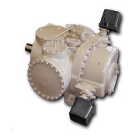
Emerson VILTER VSSG Screw Compressor Manuals
Manuals and User Guides for Emerson VILTER VSSG Screw Compressor. We have
1
Emerson VILTER VSSG Screw Compressor manual available for free PDF download: Installation, Operation And Service Manual
Emerson VILTER VSSG Installation, Operation And Service Manual (148 pages)
Single Screw Bare Shaft Compressor
Brand:
Emerson
| Category:
Air Compressor
| Size: 21 MB
Table of Contents
Important Message
3
VSG Standard Vilter Warranty Statement
4
Table of Contents
7
Section 1 • General Information
13
How to Use this Manual
13
Additional Important Notes
13
Bare Shaft Gas Compressor Model Designations
14
System Unit Identification
15
Bare Shaft Compressor
15
Compressor Unit
15
Package Unit
15
Table 1-1. VSG Standard Materials of Construction
16
Section 2 • Theory of Operation
17
Compressor
17
Capacity and Volume Control
17
Description of a Gas System for a Standard Compressor Set
18
Description of an Oil System for a Standard Compressor Set
19
Critical Applications Guidelines
19
Notice on Using Non-Vilter Oils
19
Alarm and Shutdown Readings
19
VSG Package Requirements
21
Process Gas Circuit
21
Figure 2-1. Basic Single Screw Compressor System
21
Section 3 • Installation
23
Long Term Storage Requirements
23
Long Term Storage Log
24
Instrumentation Requirements
25
Pressure
25
Temperature
25
Miscellaneous
25
Figure 3-1. Additional Instruments
26
Piping
27
Recommended Header Piping
27
Compressor Suction Piping
27
Figure 3-2. Single Compressor Suction Piping
28
Figure 3-3. Multiple Compressor Suction Piping
28
Compressor Discharge Piping
29
Figure 3-4. Multiple Compressor Suction Piping (Where Drain Back to Accumulator Is Not Possible)
29
Figure 3-5. Single Compressor Discharge Piping
29
Figure 3-6. Multiple Compressor Discharge Piping, Vertical to System
30
Figure 3-7. Multiple Compressor Discharge Piping, Horizontal to System with Options
30
Oil Line and Aftercooler Piping
31
Figure 3-8. Compressor Oil Line Piping to Air-Cooled Oil Cooler
31
Figure 3-9. Aftercooler Piping
31
Air Cooled Condenser Piping
32
Figure 3-10. Single Refrigeration Air-Cooled Condenser Piping
32
Figure 3-11. Refrigeration Multiple Air Cooled Condenser Piping
32
Allowable Flange Loads
33
Table 3-1. Maximum Allowable Flange Loads
33
Figure 3-12. Piping Elements Support
33
Testing System for Leaks
34
Hydrocarbons Systems
34
Notice on Using Non-Vilter Oils
34
Oil for Single Screw Compressors
34
Installation and Calibration of Slide Valve Actuators
35
Slide Valve Actuator Installation Instructions
35
Actuator Motor Control Module Calibration Procedure
35
Slide Valve Operation
37
Section 4 • Operation
39
Notice on Using Non-Vilter Oils
39
Safety Setpoints
39
Control System
40
Calibration
40
Starting, Stopping and Restarting the Compressor
40
Emergency Shutdown
40
Slide Valve Actuator Calibration (25972XP)
41
Slide Calibration Screen Overview
41
Calibrate Slide Valve Actuators (25972XP)
41
Figure 4-1. Slide Calibration Screen (Not in Calibration Mode)
42
Figure 4-2. Slide Calibration Screen (in Calibration Mode)
43
Figure 4-3. Actuator Inside
43
Slide Valve Actuators Calibration (for VPN 25972D Only)
44
Figure 4-5. Actuator Assembly
44
Figure 4-6. Overview, Main Menu and Instrument Calibration Screens (Compact Logix PLC)
46
Figure 4-7. Slide Calibration Screen (Compact Logix PLC)
47
Figure 4-8. Photo-Chopper
47
Table 4-1. Command Shaft Rotation Specifications
48
Section 5 • Maintenance/Service
49
Maintenance and Service Schedule
49
Additional Notes
50
Recommendations When Servicing
50
Preparation of Unit for Servicing
50
Compressor Inspection
51
Bearing Check
51
Table 5-2. Maximum Bearing Float
51
Figure 5-1. Bearing Axial Clearance Inspection
51
Table 5-3. Gate Rotor Float
52
Gaterotor Assembly Replacement
53
Removal (All VSG Models)
53
Removal (All VSG 301-701 Models)
54
Installation (All VSG Models)
56
Installation (All VSG 301-701 Models)
58
Gate Rotor Blade Removal
59
Gate Rotor Blade Installation
59
Gate Rotor Thrust Bearing Removal
59
Gate Rotor Thrust Bearing Installation
59
Gate Rotor Roller Bearing Removal
60
Gate Rotor Roller Bearing Installation
60
Compressor Shaft Seal Replacement
61
Compressor Shaft Seal Removal
61
Compressor Shaft Seal Installation
61
Maintenance Suggestion
61
Inspection of Slide Valve Assemblies in the Compressor
63
Prepare the Compressor for Servicing
63
Removal of Slide Valve Carriage Assemblies
63
Installation of Slide Valve Carriage Assemblies
64
Slide Valve Actuator Assembly Replacement
65
Removal
65
Installation
65
Actuator Installation Using Anti-Rotation Bolts
66
Slide Valve Command Shaft Assembly Replacement
68
Removal
68
Installation
68
Slide Valve Command Shaft Assembly Replacement (for the Design before June 2006)
68
Reassembly
69
Discharge Manifold Removal
69
Discharge Manifold Installation
69
Slide Valve Gear and Rack Inspection
70
Removal of Capacity or Volume Cross Shafts
70
Table 5-4. Rack Clearance Values
70
Installation of Capacity or Volume Cross Shafts
71
Main Rotor Assembly
72
Torque Specifications
72
Table 5-5. Torque Specifications (All Units, Ft.-Lbs)
72
Using a Torque Wrench Correctly
73
Nord-Lock ® Washers
73
Section 6 • Troubleshooting
75
Slide Valve Actuator Troubleshooting Guide
75
Table 6-1. Slide Valve Actuator Troubleshooting Guide (1 of 2)
75
Table 6-1. Slide Valve Actuator Troubleshooting Guide (2 of 2)
76
Slide Valve Actuator LED Blink Codes
77
Table 6-2. Slide Valve Actuator LED Blink Codes* (1 of 2)
77
Table 6-2. Slide Valve Actuator LED Blink Codes (2 of 2)
78
Troubleshooting Guide - General Problems and Solutions
79
Table 6-3. Troubleshooting Guide - General Problems and Solutions (1 of 3)
79
Table 6-3. Troubleshooting Guide - General Problems and Solutions (2 of 3)
80
Table 6-3. Troubleshooting Guide - General Problems and Solutions (3 of 3)
81
Section 7 • Warranty and Parts
83
Warranty Claim Processing
83
Process for Returning Products Covered by the Warranty
83
Procedure for Parts Not Manufactured by Vilter
83
On-Site Service Support
85
Remanufactured Gas Bare Shaft Single Screw Compressor Process
85
Explanation of Rebuild Levels
85
Bare Shaft Compressor Description
85
Section 8 • Spare Parts List
87
How to Read a Parts List and Illustration
87
Item Number
87
Description
87
Model Number
87
Vpn
87
Quantity
87
Assembly and Kit Information
87
Terms and Abbreviation Used
87
Important Notes
87
Recommended Spare Parts List
89
Gate Rotor
90
Shaft Seal
94
Tandem Shaft Seal
95
Main Rotor
96
Slide Valve Cross Shafts and End Plate
98
Slide Valve Carriage Assembly
100
Actuator and Command Shaft
104
Miscellaneous Frame Components
106
Replacement Tools
110
VSG 301-701 Replacement Parts Section
113
Gaterotor Assembly
114
Shaft Seal
117
Main Rotor, Slide Valve Cross Shafts and End Plate
118
Advertisement
Advertisement
Related Products
Emerson Vilter VSG
Emerson Vilter VSSG
Emerson VILTER VSR
Emerson Vilter VSS
Emerson Vilter VSM
Emerson Vilter VSH
Emerson Vilter VSSH
Emerson VILTER VSG
Emerson VSSG 291
Emerson VSG 210
Emerson Categories
Controller
Control Unit
Transmitter
Measuring Instruments
Fan
More Emerson Manuals
Login
Sign In
OR
Sign in with Facebook
Sign in with Google
Upload manual
Upload from disk
Upload from URL