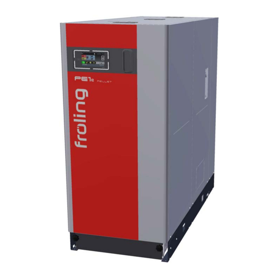
Fröling PE1e Pellet (ESP) Installation Instructions Manual
Pellet condensing boiler
Hide thumbs
Also See for PE1e Pellet (ESP):
- Operating instructions manual (68 pages) ,
- Installation instructions manual (52 pages) ,
- Service handbook (112 pages)
Table of Contents
Advertisement
Quick Links
Advertisement
Table of Contents

Related Manuals for Fröling PE1e Pellet (ESP)


Summary of Contents for Fröling PE1e Pellet (ESP)
- Page 1 Installation instructions Pellet condensing boiler PE1e Pellet (ESP) Translation of original German version of installation instructions for technicians. Read and follow all instructions and safety instructions. All errors and omissions excepted. M2440122_en | Edition 07/09/2022...
-
Page 2: Table Of Contents
Table of contents 1 General ................................. 1.1 About this manual ..........................1.2 What do we mean by condensing boiler technology................2 Safety................................2.1 Hazard levels of warnings ........................2.2 Qualification of assembly staff ......................2.3 Personal protective equipment for assembly staff ................3 Design Information............................ - Page 3 Table of contents 5.4.1 Remove boiler from pallet ......................30 5.4.2 Operating and maintenance areas of the equipment..............32 6 Assembly ..............................33 6.1 Tools required ............................33 6.2 Assembly overview ..........................33 6.3 Accessories supplied ..........................34 6.4 Installing the boiler ..........................34 6.4.1 Levelling the boiler ........................
-
Page 4: General
1 | General 1 General Thank you for choosing a quality product from Froling. The product features a state-of- the-art design and conforms to all currently applicable standards and testing guidelines. Please read and observe the documentation provided and always keep it close to the system for reference. -
Page 5: Safety
Safety | 2 2 Safety 2.1 Hazard levels of warnings This documentation uses warnings with the following hazard levels to indicate direct hazards and important safety instructions: DANGER The dangerous situation is imminent and if measures are not observed it will lead to serious injury or death. -
Page 6: Qualification Of Assembly Staff
2 | Safety 2.2 Qualification of assembly staff CAUTION Assembly and installation by unqualified persons: Risk of personal injury and damage to property During assembly and installation: r Observe the instructions and information in the manuals r Only allow appropriately qualified personnel to work on the system Assembly, installation, initial startup and servicing must always be carried out by qualified personnel: - Heating technician / building technician... -
Page 7: Design Information
Design Information | 3 3 Design Information 3.1 Overview of standards Perform installation and commissioning of the system in accordance with the local fire and building regulations. Unless contrary to other national regulations, the latest versions of the following standards and guidelines apply: 3.1.1 General standards for heating systems EN 303-5 Boilers for solid fuels, manually and automatically fed combustion... -
Page 8: Regulations And Standards For Permitted Fuels
3 | Design Information 3.1.4 Regulations and standards for permitted fuels 1. BImSchV First Order of the German Federal Government for the implementation of the Federal Law on Emission Protection (Ordinance on Small and Medium Combustion Plants) in the version published on 26 January 2010, BGBl. -
Page 9: Chimney Connection/Chimney System
Design Information | 3 3.4 Chimney connection/chimney system Connection line to the chimney Measuring port Explosion flap (for automatic boilers) Thermal insulation NOTICE! The chimney must be authorised by a smoke trap sweeper or chimney sweep. The entire flue gas system (chimney and connection) must be laid out as per ÖNORM / DIN EN 13384-1 or ÖNORM M 7515 / DIN 4705-1. -
Page 10: Connection Line To The Chimney
3 | Design Information 3.4.1 Connection line to the chimney Requirements for the connection line: ▪ this should be as short as possible and follow an upward incline to the chimney (30 - 45° recommended) ▪ thermally insulated ▪ leak-tight against overpressure MFeuV (Germany) EN 15287-1 and EN 15287-2... -
Page 11: Measuring Port
Design Information | 3 3.4.2 Measuring port Upstream of the measuring port (M) there should be a straight run-in section with a length about twice the diameter (D) of the connection line. Downstream of the measuring port (M) there should be a straight run-out section with a length about the diameter (D) of the connection line. -
Page 12: Combustion Air For Room Air-Dependent Operation
3 | Design Information 3.5 Combustion air for room air-dependent operation Boiler in room air-dependent operation Air extraction system (such as centralised dust extraction system, room ventilation) Under-pressure monitoring system Combustion air supply from outside 3.5.1 Combustion air supply at the installation room The system is operated in open flue mode, i.e. -
Page 13: Simultaneous Operation With Other Air-Drawing Systems
Design Information | 3 3.5.2 Simultaneous operation with other air-drawing systems Where the boiler is operated in room air-dependent mode with simultaneous operation of other air-drawing systems (such as room ventilation), safety devices are necessary: ▪ Air pressure monitor ▪ Flue gas thermostat ▪... -
Page 14: Combustion Air For Room Air-Independent Operation (Rul)
3 | Design Information 3.6 Combustion air for room air-independent operation (RUL) Boiler Air extraction system (such as centralised dust extraction system, room ventilation) Combustion air supply from outside (irrespective of ambient air) 3.6.1 Definition of terms There is a central air connection on the back of the boiler. If appropriate supply air and flue gas connections are installed, the boiler can be classified according to EN 15035 as a type C / type C... -
Page 15: Supply Air Line
Design Information | 3 3.6.2 Supply air line NOTICE! Install the combustion air supply (piping) in accordance with the applicable standards Ü "Overview of standards" [} 7] r Connect the supply air line leak-tight to the connection on the boiler Ä Refer to the dimensions of the supply air line connection on the boiler in the Technical Data When dimensioning pipe bends in the supply air line, ensure that: The ratio of the radius of curvature (r) to pipe diameter (d) is greater than 1... -
Page 16: Domestic Hot Water
3 | Design Information 3.7 Domestic hot water Unless contrary to other national regulations, the latest versions of the following standards and guidelines apply: Austria: ÖNORM H 5195 Switzerland: SWKI BT 102-01 Germany: VDI 2035 Italy: UNI 8065 Observe the standards and also follow the recommendations below: r Aim for a pH value of between 8.2 and 10.0. -
Page 17: Pressure Maintenance Systems
Design Information | 3 Additional requirements for Switzerland The filling and make-up water must be demineralised (fully purified) ▪ The water must not contain any ingredients that could settle and accumulate in the system ▪ This makes the water non-electroconductive, which prevents corrosion ▪... -
Page 18: Storage Tank
3 | Design Information 3.9 Storage tank NOTICE In principle it is not necessary to use a storage tank for the system to run smoothly. However we recommend that you use the system with a storage tank, as this ensures a continuous supply of fuel in the ideal output range of the boiler. -
Page 19: Condensate Drainage
Design Information | 3 3.12 Condensate drainage The condensate must be continuously drained into the waste water system in accordance with local regulations for heating systems with condensing boiler technology. In respect of the condensate drainage, ensure: ▪ Line of raw material resistant to condensate ▪... -
Page 20: Technology
4 | Technology 4 Technology 4.1 Dimensions Item Description Unit 45-60 Boiler length 1690 Total length 1780 Distance between flow connection and side of boiler Distance between fresh water connection and side of boiler Distance between flue gas pipe connection and side of boiler Distance between return connection and side of boiler Distance between condensation drain connection and side of boiler... -
Page 21: Components And Connections
Technology | 4 4.2 Components and connections Item Description PE1e Pellet 45-60 condensing boiler Pellet suction line connection DA 50 m Return-air line connection DA 50 m Boiler flow Sleeve 1 1/4" (internal thread) Fresh water connection 3/4" (external thread) Mixing valve for the return temperature control Pump for the return temperature control Flue gas pipe connection... -
Page 22: Technical Data
4 | Technology 4.3 Technical data 4.3.1 PE1e Pellet condensing boiler Description PE1e Pellet condensing boiler Nominal heat output 49.5 55.0 60.5 66.0 Electrical connection 230V / 50Hz / fused C16A Boiler weight (without water content) Total boiler capacity (water) Pellet container capacity Ash container capacity 37 / 12... -
Page 23: Pe1E Pellet Condensing Boiler Esp
Technology | 4 Additional data for regulation (EU) 2015/1189 Description PE1e Pellet condensing boiler Heating up mode automatic Condensing boiler Solid fuel boiler for combined heat and power Combined heating system Storage tank volume Ü "Storage tank" [} 18] Characteristics when operated exclusively with the preferred fuel Useful heat delivered at rated heat output (P 49.5 55.0... - Page 24 4 | Technology Description PE1e Pellet condensing boiler ESP Airborne sound level dB(A) < 70 Permitted fuel as per EN ISO 17225 Fuel in accordance with EN ISO 17225 - Part 2: Wood pellets class A1 / D06 Test book number PB 196 PB 198 PB 200...
- Page 25 Technology | 4 Additional data for regulation (EU) 2015/1189 Description PE1e Pellet condensing boiler ESP Heating up mode automatic Condensing boiler Solid fuel boiler for combined heat and power Combined heating system Storage tank volume Ü "Storage tank" [} 18] Characteristics when operated exclusively with the preferred fuel Useful heat delivered at rated heat output (P 49.5 55.0...
-
Page 26: Boiler Data For Planning The Flue Gas System
4 | Technology 4.3.3 Boiler data for planning the flue gas system Description PE1e Pellet condensing boiler Flue gas temperature at nominal load °C Flue gas temperature at partial load - volume concentration at nominal load 11.8 12.3 12.3 13.3 volume concentration at partial load 10.3 10.3... -
Page 27: External Suction Module
Technology | 4 4.4 External suction module Dimensi Description Unit Size 1 Size 2 Length of suction module Width of suction module Height of suction module Total height incl. hose connection Return-air line connection (line to suction point) Return-air line connection (line to boiler) M2440122_en | Installation instructions Pellet condensing boiler PE1e Pellet (ESP) -
Page 28: Transport And Storage
5 | Transport and storage 5 Transport and storage 5.1 Delivery configuration Item Description Unit PE1e Pellet 45-60 condensing boiler Length 1870 Width Height 1995 Weight 5.2 Temporary storage If the system is to be assembled at a later stage: r Store components at a protected location, which is dry and free from dust Ä... -
Page 29: Positioning
Transport and storage | 5 5.3 Positioning NOTICE Damage to components if handled incorrectly r Follow the transport instructions on the packaging r Transport components with care to avoid damage r Protect the packaging against damp conditions r Pay attention to the pallet's centre of gravity when lifting r Position a fork-lift or similar lifting device at the pallet and bring in the components If the boiler cannot be brought in on the pallet: r Remove the cardboard and take the boiler off the pallet... -
Page 30: Positioning At The Installation Site
5 | Transport and storage 5.4 Positioning at the installation site 5.4.1 Remove boiler from pallet r Cut through the strapping and lift off the cardboard r Pull out the floor insulation to the rear r Release the transport protection and lift the boiler off the pallet TIP: We recommend using Fröling’s KHV 1400 boiler lifting system to make pallet removal easier TIP: use Froling’s KHV 1400 boiler lifting system to help remove the pallet! - Page 31 Transport and storage | 5 r Pull out both ash containers r Remove upper covers r Undo four screws on the right side panel r Unhinge the side panel r Undo two screws and pull the bracket out to the front r Position a fork-lift or similar lifting device with a suitable load-bearing capacity at the base frame r Lift it and transport it to the intended position...
-
Page 32: Operating And Maintenance Areas Of The Equipment
5 | Transport and storage 5.4.2 Operating and maintenance areas of the equipment ▪ The system should generally be set up so that it is accessible from all sides to allow quick and easy maintenance! ▪ Regional regulations regarding necessary maintenance areas for inspecting the chimney should be observed in addition to the specified distances! ▪... -
Page 33: Assembly
Assembly | 6 6 Assembly 6.1 Tools required The following tools are required for assembling the boiler and suction module: ▪ Spanner or box wrench set ▪ Set of Allen keys ▪ Flat head and cross-head screwdrivers ▪ Pipe wrench or water pump pliers (1") –... -
Page 34: Accessories Supplied
6 | Assembly 6.3 Accessories supplied The following accessories are included in the delivery and are necessary exclusively for operation of the boiler. Flat scraper Stainless steel cleaning brush Ø 56 x 1350 for condensing boiler heat exchanger Plastic cleaning brush 25 x 50 x 750 SW 13 mm socket wrench Cleaning brush 24 x 50 x 1200 6.4 Installing the boiler... -
Page 35: Install Balancing Valve (Optional)
Assembly | 6 6.4.2 Install balancing valve (optional) r Remove the rear cover at the top of the boiler r Remove rear side panels SW 41 mm r Remove pipe section Ä Hexagonal spanner dimension 41 mm r Install line regulating valve instead Ä... - Page 36 6 | Assembly r Set the knob on the housing of the mixing drive to manual mode (1) r Turn the mixing drive counter clockwise at the hand lever until it stops Ä The mixer valve completely opens the system return Ä...
-
Page 37: Installing The Discharge System
Assembly | 6 6.5 Installing the discharge system 6.5.1 Installing the external suction module The pellets are loaded using an external suction module. The suction module is installed in the return-air line between the boiler and the suction point. The following points should be noted for assembly: ▪... - Page 38 6 | Assembly r Unwind the cable of the suction turbine and feed it through the opening of the housing underside r Remove the protective cap on the underside of the suction module r Lay the return air line from the suction point to the suction module and fix it to the pressure side (position 1) with a hose clamp r Fix the second part of the return-air line to the under-pressure side (position 2) with a hose clamp and lay the line to the boiler...
-
Page 39: Connect The Suction Hoses To The Boiler
Assembly | 6 6.5.2 Connect the suction hoses to the boiler r Remove the front cover r Fix the suction hoses to the connections using hose clamps Ä Left-hand connection: Return-air line Ä Right-hand connection: Suction hose (PELLETS sticker) Ü NOTICE! When connecting the lines, pay attention to equipotential bonding, "Assembly information for hose lines"... -
Page 40: Assembly Information For Hose Lines
6 | Assembly 6.5.3 Assembly information for hose lines < 0,5m < 0,5m R > 30cm Please note the following with regard to the hose lines used in Froling vacuum discharge systems: ▪ Do not kink the hose lines! Minimum bending radius = 30cm ▪... - Page 41 Assembly | 6 Potential equalisation When connecting the hose lines to the individual connections, ensure there is consistent potential equalisation throughout the line. r Expose approximately 8 cm of the earth wire at the end of the hose line Ä TIP: Slit the insulation open along the wire with a knife r Bend the earth wire inwards in a loop Ä...
-
Page 42: Installing The Condensation Drain
6 | Assembly 6.6 Installing the condensation drain r Remove the cover underneath the induced draught unit fan r Cut the intake pipe (A) of the siphon to the desired length r Push on both union nuts (B) and wedge seal r Insert the intake pipe (A) into the siphon (D), press on the wedge seal and screw on the union nut r Push the second union nut outwards, insert the seal (C) and screw it onto the heat... -
Page 43: Connect The Connection Line To The Chimney
Assembly | 6 6.7 Connect the connection line to the chimney The flue gas pipe connection of the condensing boiler has a larger diameter than the connecting pipe to be connected to the chimney. This allows the condensate accumulating in the flue gas line to flow back into the boiler unhindered. To prevent the exhaust gas from escaping at the connection, this point must be sealed conscientiously. -
Page 44: Hydraulic Connection
6 | Assembly 6.8 Hydraulic connection Safety valve ▪ Safety valve as per ÖNORM EN ISO 4126-1, diameter as per EN 12828 or national regulations ▪ The safety valve must be installed in an accessible place on the heat generator or in direct proximity in the flow pipe in such a way that it cannot be shut off Diaphragm expansion tank ▪... -
Page 45: Electrical Connection
Assembly | 6 6.9 Electrical connection DANGER When working on electrical components: Risk of electrocution! When work is carried out on electrical components: r Always have work carried out by a qualified electrician r Observe the applicable standards and regulations Ä... -
Page 46: Board Overview
6 | Assembly 6.9.1 Board overview Item Designation Item Designation Service interface Pellet module High-limit thermostat STL Mains connection plug Main switch Device connection terminal Core module Return mixer module Pellet module expansion (optional) Digital module (optional) Pellet module 6.9.2 Mains connection r Open the insulated door and remove the front cover r Undo four screws and contact washers and remove the controller cover M2440122_en | Installation instructions Pellet condensing boiler PE1e Pellet (ESP) -
Page 47: External Suction Module
Assembly | 6 r Lay the mains connection cable to the front via the cable duct (A) at the rear to the boiler controller. r Connect the power supply to the plug (B) and fix the mains connection cable to the strain relief (C) 6.9.3 External suction module FRPEM... -
Page 48: Set Condensing Boiler Heat Exchanger In The Software
6 | Assembly 6.10 Set condensing boiler heat exchanger in the software The condensing boiler heat exchanger must be activated in the software as follows (min. V50.04 B05.15): (change “Condensation heat exchanger present” parameter to “YES”). In addition, various parameters related to cleaning can be set as required. NOTICE! In addition, observe the operating instructions of the boiler controller! 6.10.1 Condenser Flue gas... -
Page 49: Final Installation Steps
Assembly | 6 6.11 Final installation steps r Attach the controller cover with four screws and contact washers r Close the insulating door r Install both side panels r Slide the floor insulation underneath the boiler from the rear r Place the covers on the boiler 6.11.1 Install the brackets for accessories r Using appropriate fasteners, attach the brackets to the wall on the boiler r Attach the accessories to the brackets... -
Page 50: Insulate The Connection Line
6 | Assembly 6.11.2 Insulate the connection line When using the optionally available thermal insulation supplied by Fröling GesmbH, perform the following steps: r Cut the half shells of thermal insulation to length and lay them on the connection line r Create an opening for access to the measuring port r Apply protective foil at the projecting lugs r Glue the half shells to each other... -
Page 51: Start-Up
Start-up | 7 7 Start-up 7.1 Before commissioning / configuring the boiler The boiler must be configured to the heating system during initial start-up! NOTICE Optimum efficiency and efficient, low-emission operation can only be guaranteed if the system is set up by trained professionals and the standard factory settings are observed. Take the following precautions: r Initial startup should be carried out with an authorised installer or with Froling customer services... -
Page 52: Initial Startup
7 | Start-up 7.2 Initial startup 7.2.1 Permitted fuels Wood pellets Wood pellets made from natural wood with a diameter of 6 mm Note on standards Fuel acc. to EN ISO 17225 - Part 2: Wood pellets class A1 / D06 and/or: ENplus / DINplus certification scheme General note:... -
Page 53: Decommissioning
Decommissioning | 8 8 Decommissioning 8.1 Mothballing The following measures should be taken if the boiler is to remain out of service for several weeks (e.g. during the summer): r Clean the boiler thoroughly and close the doors fully If the boiler is to remain out of service during the winter: r Have the system completely drained by a qualified technician Ä... -
Page 54: Appendix
9 | Appendix 9 Appendix 9.1 Dismantling for location where positioning is difficult 9.1.1 Tools required Pliers wrench Ratchet with extension and socket set Pipe wrench Spanner or box wrench set Cable tie Trox screwdriver Box cutter Slotted screwdriver Diagonal cutting pliers NOTICE! All disassembled components of the boiler must be stored in a secure place (dust-free, dry) until the parts are assembled again. -
Page 55: Overview Of Disassembly Steps
Appendix | 9 9.1.2 Overview of disassembly steps When used in PE1e Pellet 45-60 pellet boiler and PE1e Pellet 45-60 pellet condensing boiler, boiler components can be disassembled for easier installation. When disassembling these boiler components, the following dimensions and weights can be expected. - Page 56 9 | Appendix Removing the condensing boiler heat exchanger (ca. 479-395 kg) 1460 Removing the ash removal screws and front boiler floor (ca. 460-376 kg) 1055 Removing the boiler floor (ca. 425-341 kg) 1055 1) When removing the WOS system and firebricks, the weight can be reduced considerably Ü...
-
Page 57: Dismantling The Cardboard Box And Pallet
Appendix | 9 9.1.3 Dismantling the cardboard box and pallet r Cut through the strapping and lift off the cardboard r Remove the transport locks at the boiler bottom - 4 round-head screws M10 x 50 r Pull out the floor insulation to the rear r Lift boiler from pallet Ä... -
Page 58: Dismantling The Cladding And Controller Box
9 | Appendix 9.1.4 Dismantling the cladding and controller box r Remove upper cover r Open the front door and remove the controller’s cover - 4 fillister head screws M4 x 8 including contact washer r Remove the cover behind the control - 2 fillister head screws M4 x 8 r Remove the locking plate near the upper door hinge - 2 fillister head screws M4 x 8... - Page 59 Appendix | 9 r Loosen the star-shaped knobs and swivel to one side r Fold the cover plate forward r Pull out both ash containers r Remove the side panels on the right-hand side - 4 fillister head screw M6 x 12 for each side panel r Remove the screws and pull the console away from the boiler - 2 hexagonal screws M8 x 25 r Remove the cable ties from the strain reliefs in the controller box...
- Page 60 9 | Appendix Cut the following components on core module (KM) to length and mark the cables: Core module KM-27 Induced draught unit fan KM-15 Flue gas temperature sensor KM-25 Boiler sensor KM-13 Lambda probe KM-24 Return feed sensor KM-08 Air flap KM-18 Flue gas temperature...
- Page 61 Appendix | 9 Cut the following components on hydraulic module (HY), pellet module (PM), and return mixer module (RL) to length and mark: Hydraulic module HY-14 Pump 0.1 HY-05 Control signal AO-P1 Pellet module PM-18 Door contact switch PM-08 Feed screw PM-14 Gate valve PM-07...
- Page 62 9 | Appendix r Remove the covers of the cable ducts - loosen the 5 fillister head screws M4 x 8 on the top - loosen the 6 fillister head screws M4 x 8 on the inside r Cut the cable on the safety temperature limiter to length (grounding, 1, T120) r Remove the cap on the safety temperature limiter, loosen the nut underneath and thread the safety temperature limiter (STL) out of the controller box Ä...
- Page 63 Appendix | 9 r Remove the side panels on the left-hand side - 5 fillister head screws M4 x 8 - 4 fillister head screws M6 x 12 r PE1e Pellet condenser: Remove the rear panel -1 fillister head screw M4 x 8 r Disconnect the supply line and control line at the induced draft fan to length r PE1e Pellet condenser: Remove the connection of the flushing device on the right- hand side of the condensing boiler heat exchanger...
- Page 64 9 | Appendix r PE1e Pellet condenser: Remove the cover plates for the induced draught fan and the back panels - 11 fillister head screws M4 x 8 - 2 fillister head screws M6 x 12 r Remove the ignition tube - 2 hexagonal screws M8 x 25 Ä...
- Page 65 Appendix | 9 r Wind up the cables of the following components and use cable ties to secure them Ä Underpressure sensor cartridge (E) Ä Drive of the tipping grate (F) Ä Drive of the air flap (G) r PE1e Pellet condenser: Remove the siphon on the underside of the condensing boiler heat exchanger r PE1e Pellet condenser: Remove the cover plate from the bottom of the boiler - 1 fillister head screw M6 x 12...
- Page 66 9 | Appendix r Unplug the cable from the shunt pump (A) r Remove the mixer drive (B) and use cable ties to attach the mixer drive to the cable duct on the right-hand side r Unplug the extension cable of the lambda probe (C) r Remove the cable tie and pull the flow temperature sensor (D) and the STL sensor (E) out of the immersion sleeve r PE1e Pellet condenser: Remove the cable tie and pull the flue gas temperature...
-
Page 67: Removing The Pellet Container And Stoker
Appendix | 9 r PE1e Pellet: Pull the flue gas temperature sensor at the induced draught unit housing (I) from the immersion sleeve r TIP: Install the covers of the upper cable ducts r Remove the cable duct on the right-hand side - 2 fillister head screws M6 x 12 - 1 round-head screw M8 x 16 Ä... -
Page 68: Removing The Condensing Boiler Heat Exchanger
9 | Appendix r Remove stoker and gasket - 4 hexagonal screws M8 x 25 9.1.6 Removing the condensing boiler heat exchanger r Remove the corrugated hose from the flow of the condensing heat exchanger r Remove the top cover on the condensing boiler heat exchanger - 6 hexagonal nuts M8 (brass) r Remove the pipe locking pin from the mounting plate and remove the WOS mount along with the springs... -
Page 69: Removing The Ash Removal Screws And Front Boiler Floor
Appendix | 9 r Remove the screws and unhook the condensing boiler heat exchanger at the bottom part - 4 hexagonal screws M8 x 25 r Remove the rear part of the bottom of the boiler - 4 hexagonal screws M8 x 25 9.1.7 Removing the ash removal screws and front boiler floor r Remove the front cover - 4 hexagonal screws M8 x 45... - Page 70 9 | Appendix r Dismantle the follower of the ash rake - 2 hexagonal screws M8 x 40 r Remove the shaft lock and pull the gear off the worm shaft - hexagonal screw M8 x 16 r Remove the key from the shaft groove r Pull out the right-hand side ash screw approx.
-
Page 71: Removing The Boiler Floor
Appendix | 9 9.1.8 Removing the boiler floor r Remove the bulkhead plate from the rear panel - 2 fillister head screws M6 x 12 r Remove the angle from the front panel - 2 hexagonal screws M8 x 16 r Lift the boiler off the boiler’s bottom - 3 round-head screws M8 x 30 M2440122_en | Installation instructions Pellet condensing boiler PE1e Pellet (ESP) -
Page 72: Disassembly Of The Wos System In Order To Reduce Weight (Optional)
9 | Appendix 9.1.9 Disassembly of the WOS system in order to reduce weight (optional) NOTICE! When the WOS system is dismantled, the weight of the boiler is reduced by 32 kg. r Remove the locking screws and open the reversing chamber cover - 2 hexagonal screws M10 x 75 r Unhook tension springs on the connecting rod of the WOS r Pull out the spring cotter pin and remove bolt... - Page 73 Appendix | 9 r Dismantle the securing plate and pull out the lifting unit of the WOS - 2 hexagon nuts M8 (copper) M2440122_en | Installation instructions Pellet condensing boiler PE1e Pellet (ESP)
-
Page 74: Disassembly Of The Firebricks In Order To Reduce Weight (Optional)
9 | Appendix 9.1.10 Disassembly of the firebricks in order to reduce weight (optional) NOTICE! When removing the firebricks, the weight of the boiler is reduced by approx. 52 kg. WARNING! Damage to the firebricks and gaskets due to careless handling may cause fault in the combustion and malfunction of the boiler. - Page 75 Appendix | 9 r Pull the side firebricks out of the combustion chamber TIP: Push a screwdriver into the center air hole and lift the firebrick using the screwdriver r Pull the front and rear firebrick out of the combustion chamber M2440122_en | Installation instructions Pellet condensing boiler PE1e Pellet (ESP)
- Page 76 Manufacturer’s address Froling srl Froling SARL Fröling Heizkessel- und Zweigniederlassung Behälterbau GesmbH Aschheim Industriestraße 12 Max-Planck-Straße 6 Via J. Ressel 2H 1, rue Kellermann A-4710 Grieskirchen 85609 Aschheim I-39100 Bolzano (BZ) F-67450 Mundolsheim +43 (0) 7248 606 0 +49 (0) 89 927 926 0 +39 (0) 471 060460 +33 (0) 388 193 269 info@froeling.com...
Need help?
Do you have a question about the PE1e Pellet (ESP) and is the answer not in the manual?
Questions and answers