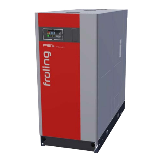
Fröling PE1e Pellet 45 Installation Instructions Manual
Electrostatic particle separator
Hide thumbs
Also See for PE1e Pellet 45:
- Installation instructions manual (76 pages) ,
- Operating instructions manual (68 pages) ,
- Service handbook (112 pages)
Table of Contents
Advertisement
Quick Links
Advertisement
Table of Contents

Subscribe to Our Youtube Channel
Summary of Contents for Fröling PE1e Pellet 45
- Page 1 Installation instructions Electrostatic particle separator PE1e Pellet 45-60 Translation of original German version of installation instructions for technicians. Read and follow all instructions and safety instructions. All errors and omissions excepted. M2420223_en | Edition 13/02/2023...
- Page 2 1 | General 1 General The pellet boiler PE1e Pellet 45-60 can be equipped with an electrostatic particle separator. r Switch off the boiler and allow it to cool down r Switch off the power supply to the boiler CAUTION...
-
Page 3: Materials Supplied
General | 1 1.1 Materials supplied Control unit Cable grommet Frame for distributor box High-voltage cable Hook in plates Electrode unit Bulkhead plate Screw-in plate M2420223_en | Installation instructions Electrostatic particle separator... -
Page 4: Boiler Preparation
2 | Assembly 2 Assembly 2.1 Boiler preparation r Remove the cover on the upper side of the boiler r Removing the side panels - 4x lens-head screws M6 x 12 per side panel r Remove the cover of the cable duct - loosen the 3 lens-head screws M4 x 8 on the top - loosen the 4 lens-head screws M4 x 8 on the inside (A) r Open the insulated door and remove the controller cover behind... - Page 5 Assembly | 2 r Unhook tension springs on the connecting rod of the WOS Ä TIP: Mark hook-in positions r Lift the driver lever in the upper area (A) and remove the pin as well as spring cotter r Dismantle the drive lever and remove the key from WOS shaft - 1 hexagonal screw M8 x 16 r Remove the heat exchanger cover - 4x hexagonal screws M8 x 45...
- Page 6 2 | Assembly 2.2 Particle separator assembly r Install screw-in plate on the rear connection plate - 2x hexagonal screws M6 x 12 r Release the pin clasp (A) on the connection plate r Hook the hook-in plate into both pins and secure with the pin clasp (A) Ä...
- Page 7 Assembly | 2 r Install the side heat exchanger cover on the body of the boiler - 4x hexagonal screws M8 x 45 r Remove bottom cover - 4x hexagonal screws M8 x 30 r Remove the top cover - 4x hexagonal screws M8 x 30 r Insert the electrode unit into the bottom opening and install - 4x hexagonal screws M8 x 30 Ä...
- Page 8 2 | Assembly r Secure driver lever with pin and spring cotter r Hook tension springs on the connecting rod of the WOS Ä Use the previously marked holes For room air-independent operation: r Seal the hose support (A) thread with Teflon and screw into the electrode unit in the sleeve r Slide the silicone hose onto the hose support r Remove round perforation (A) on the upper frame and remove the burrs using a half-...
-
Page 9: Electrical Connection
Assembly | 2 2.3 Electrical connection r Run the high voltage cable from the HV module to the electrode unit Ä Use cable ties to attach the high voltage cable to the side frame r Insert the connector into the electrode unit and tighten the connection Ä... - Page 10 2 | Assembly HY-01 / HY-02 AN-03 / AN-04 r Connect the bus connection from the hydraulic module (C) in the boiler controller to the analogue module (D) in the control unit Ä Connect the bus cable at an available socket Ä...
-
Page 11: Final Installation Steps
Assembly | 2 2.4 Final installation steps r Install controller cover - 4x lens-head screws M4 x 8 incl. contact washer r Close the insulating door r Install side panel - 4x lens-head screws M6 x 12 per side panel r Place the cover on the boiler 2.5 Configuring the particle separator in the controller In the controller, navigate to the “Boiler type”... -
Page 12: Manufacturer's Address
Manufacturer’s address Froling srl Froling SARL Fröling Heizkessel- und Zweigniederlassung Behälterbau GesmbH Aschheim Industriestraße 12 Max-Planck-Straße 6 Via J. Ressel 2H 1, rue Kellermann A-4710 Grieskirchen 85609 Aschheim I-39100 Bolzano (BZ) F-67450 Mundolsheim +43 (0) 7248 606 0 +49 (0) 89 927 926 0 +39 (0) 471 060460 +33 (0) 388 193 269 info@froeling.com...


Need help?
Do you have a question about the PE1e Pellet 45 and is the answer not in the manual?
Questions and answers