
Related Manuals for Huawei PAC3000S12-T1 PSU


Summary of Contents for Huawei PAC3000S12-T1 PSU
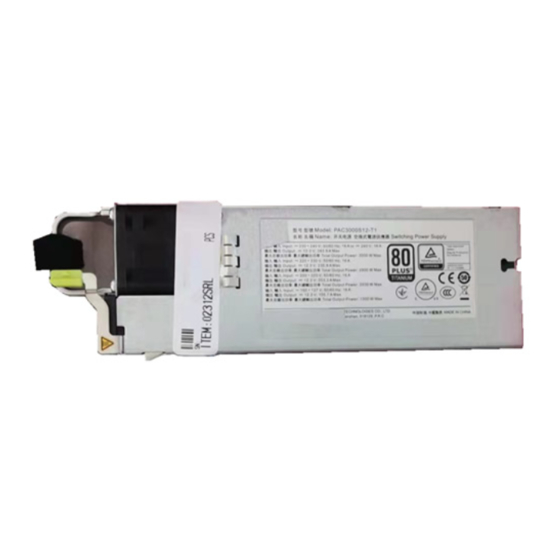
- Page 1 PAC3000S12-T1 PSU Technical Manual Issue Date 2020-05-18 HUAWEI TECHNOLOGIES CO., LTD.
-
Page 2: About This Document
PAC3000S12-T1 PSU Technical Manual About This Document About This Document Purpose This document describes the PAC3000S12-T1 power supply unit (PSU), including its electrical specifications, features, applications, and communication. The figures provided in this document are for reference only. Intended Audience This document is intended for: ●... - Page 3 PAC3000S12-T1 PSU Technical Manual About This Document Change History Changes between document issues are cumulative. The latest document issue contains all the changes made in earlier issues. Issue 1.0 (2020-05-18) This issue is the first release.
-
Page 4: Table Of Contents
PAC3000S12-T1 PSU Technical Manual Contents Contents About This Document......................... i 1 Product Overview........................1 2 Electrical Specifications......................3 2.1 Environmental..................................3 2.2 Input......................................4 2.3 Output......................................7 2.4 Efficiency....................................13 2.5 Protection....................................14 2.6 Detection Precision................................19 3 Characteristic Curves......................21 4 Typical Waveforms........................ - Page 5 PAC3000S12-T1 PSU Technical Manual Contents 9.11 I_MON....................................44 9.12 PS_INTERRUPT..................................45 9.13 SMART_ON................................... 45 9.14 EFUSEV....................................46 10 Communication........................47 10.1 Hardware Specifications..............................47 10.1.1 I2C Signal................................... 47 10.1.2 I2C Address..................................47 10.1.3 SCL and SDA..................................48 10.1.4 Data Transmission Mode.............................. 48 10.1.5 I2C Bus Timeout................................
-
Page 6: Product Overview
PAC3000S12-T1 PSU Technical Manual 1 Product Overview Product Overview Features ● Efficiency: ≥ 96% (T = 25°C; V = 230 V AC; 50% load, without fans) ● Dimensions (L x W x H): 188.00 mm x 68.00 mm x 40.30 mm (7.402 in. x 2.677 in. - Page 7 PAC3000S12-T1 PSU Technical Manual 1 Product Overview Model Naming Convention Applications Servers 1 — Embedded power 2 — AC input 3 — Output power: 3000 W 4 — Single output 5 — Output voltage: 12 V DC 6 — Titanium energy efficiency certification...
-
Page 8: Electrical Specifications
PAC3000S12-T1 PSU Technical Manual 2 Electrical Specifications Electrical Specifications 2.1 Environmental Parameter Minimum Typical Maximum Unit Notes & Conditions Operating temperature °C ● The PSU can start at a temperature of – 10°C, and there are no requirements on its performance. -
Page 9: Input
PAC3000S12-T1 PSU Technical Manual 2 Electrical Specifications Parameter Minimum Typical Maximum Unit Notes & Conditions Altitude –60 5000 When the PSU is not working, it can be placed at an altitude of 15,000 m. Atmospheric pressure The entire PSU specification meets the... - Page 10 PAC3000S12-T1 PSU Technical Manual 2 Electrical Specifications Parameter Minimum Typical Maximum Unit Notes & Conditions = 230 V AC/50 Hz, 10–20% load = 230 V AC/50 Hz, 20–30% load = 230 V AC/50 Hz, ≥ 30% load THDv When the THDv is less than 10% the PSU works properly.
- Page 11 PAC3000S12-T1 PSU Technical Manual 2 Electrical Specifications Parameter Minimum Typical Maximum Unit Notes & Conditions Input overcurrent or short If an internal fault circuit protection occurs in the PSU, the upstream C32 circuit breaker is not allowed to trip. AC input system...
-
Page 12: Output
PAC3000S12-T1 PSU Technical Manual 2 Electrical Specifications Type Harmonic order (n) Maximum permissible harmonic current (A) Even harmonics 1.08 0.43 0.30 8 ≤ n ≤ 40 Figure 2-1 Dual-live-wire input 2.3 Output Parameter Output Minimum Typical Maximum Unit Notes & Conditions Number of outputs There is one output. - Page 13 PAC3000S12-T1 PSU Technical Manual 2 Electrical Specifications Parameter Output Minimum Typical Maximum Unit Notes & Conditions 2500 3000 = 200–230 V AC, = 200–230 V DC The output power increases linearly with the input voltage. Figure 2-2 2500 = 180–200 V AC, = 180–200 V DC...
- Page 14 PAC3000S12-T1 PSU Technical Manual 2 Electrical Specifications Parameter Output Minimum Typical Maximum Unit Notes & Conditions 203.3 = 200–230 V AC, = 200–230 V DC The maximum output current increases linearly with the input voltage. 203.3 = 180–200 V AC, = 180–200 V DC...
- Page 15 PAC3000S12-T1 PSU Technical Manual 2 Electrical Specifications Parameter Output Minimum Typical Maximum Unit Notes & Conditions Dynamic overshoot MV12/ 11.4 12.6 Current change rate: amplitude 0.5 A/µs, T = 10 ms; SV12 load: 25%–50%–25%; 50%–75%–50%; 50%–100%–50%. With the minimum capacitive load 5000 µF, MV12 acceptance...
- Page 16 PAC3000S12-T1 PSU Technical Manual 2 Electrical Specifications Parameter Output Minimum Typical Maximum Unit Notes & Conditions Temperature –0.02 0.02 %/°C Rated input voltage coefficient = 230 V AC/240 V DC), rated load, full operating temperature range Current sharing –5 ≥ 50% load (rated...
- Page 17 PAC3000S12-T1 PSU Technical Manual 2 Electrical Specifications Parameter Output Minimum Typical Maximum Unit Notes & Conditions 6.00 8.20 Figure 2-2 Derating curve ● During the isolation process for output overvoltage protection failure, the MV12 busbar voltage should not be lower than 11.4 V DC.
-
Page 18: Efficiency
PAC3000S12-T1 PSU Technical Manual 2 Electrical Specifications 2.4 Efficiency Output Minimum Typical Maximum Unit Notes & Conditions Efficiency (MV12) = 230 V AC, T 25°C, 80 Plus Titanium efficiency–certified, 10% rated load (without fans) = 230 V AC, T 25°C, 80 Plus Titanium efficiency–certified,... -
Page 19: Protection
PAC3000S12-T1 PSU Technical Manual 2 Electrical Specifications Output Minimum Typical Maximum Unit Notes & Conditions = 230 V AC/240 V DC, T = 25°C, MV6/8A (without fans) 2.5 Protection AC input Parameter Minimum Typical Maximum Unit Notes & Conditions Input overvoltage... - Page 20 PAC3000S12-T1 PSU Technical Manual 2 Electrical Specifications 240HVDC input Parameter Minimum Typical Maximum Unit Notes & Conditions Input overvoltage Self-recovery protection threshold Hysteresis ≥ 5 V Input overvoltage recovery threshold Input undervoltage Self-recovery protection threshold Hysteresis ≥ 5 V Input undervoltage...
- Page 21 PAC3000S12-T1 PSU Technical Manual 2 Electrical Specifications Parameter Output Minimum Typical Maximum Unit Notes & Conditions Output overcurrent MV12 Latch-off mode, T > protection 100 ms Latch-off mode, T > 4 ms SV12 The PSU enters the MV12 mode after it...
- Page 22 PAC3000S12-T1 PSU Technical Manual 2 Electrical Specifications Parameter Output Minimum Typical Maximum Unit Notes & Conditions Overtemperature °C ● In the normal protection input range, the PSU can be protected against overtemperature and shut down only when the ambient temperature is higher than 60°C.
- Page 23 PAC3000S12-T1 PSU Technical Manual 2 Electrical Specifications Parameter Output Minimum Typical Maximum Unit Notes & Conditions the PSU can enter MV12 mode. ● If the PSU experiences overtemperature in MV6 mode, it will shut down output. When the temperature restores to...
-
Page 24: Detection Precision
PAC3000S12-T1 PSU Technical Manual 2 Electrical Specifications 1. Unlatch mode of output overvoltage protection (the PSU unlatches if any of the following requirements is met): Input is recovered after AC power has failed for 2s; the INSTALLED signal changes from low level to high level;... - Page 25 PAC3000S12-T1 PSU Technical Manual 2 Electrical Specifications Parameter Minimum Typical Maximum Unit Notes & Conditions –5 = 25℃ to 35°C, V 230 V AC, V = 270 V DC; 300 W< P < 750 –3 = 25℃ to 35°C, V...
-
Page 26: Characteristic Curves
PAC3000S12-T1 PSU Technical Manual 3 Characteristic Curves Characteristic Curves Conditions: T = 25°C unless otherwise specified Efficiency curve Power dissipation curve... -
Page 27: Typical Waveforms
PAC3000S12-T1 PSU Technical Manual 4 Typical Waveforms Typical Waveforms 4.1 Turn-on/Turn-off Conditions: T = 25°C unless otherwise specified Startup by power-on (V = 230 V AC) Shutdown by power-off (V = 230 V AC) Startup by power-on (V = 240 V DC) -
Page 28: Output Voltage Dynamic Response
PAC3000S12-T1 PSU Technical Manual 4 Typical Waveforms 4.2 Output Voltage Dynamic Response Conditions: T = 25°C unless otherwise specified Output voltage dynamic response Output voltage dynamic response = 230 V AC; load: 25%–50%–25%; 0.5 A/μs; = 230 V AC; load: 50%–75%–50%; 0.5 A/μs;... - Page 29 PAC3000S12-T1 PSU Technical Manual 4 Typical Waveforms Output voltage dynamic response Output voltage dynamic response = 230 V AC; load: 65%–130%–65% (1650 = 240 V DC; load: 25%–50%–25%; 0.5 A/μs; W–3000 W–1650 W); 0.5 A/μs; T = 1s–10 ms– T = 10 ms; P = 2800 W;...
-
Page 30: Output Voltage Ripple
PAC3000S12-T1 PSU Technical Manual 4 Typical Waveforms Output voltage dynamic response Output voltage dynamic response = 240 V DC; load: 65%–100%–65%; 2 A/μs; = 240 V DC; load: 65%–130%–65% (1650 T = 1 ms; P = 2800 W; MV12) W–3000 W–1650 W); 0.5 A/μs; T = 1s–10 ms–... -
Page 31: Energy Saving Feature
PAC3000S12-T1 PSU Technical Manual 5 Energy Saving Feature Energy Saving Feature 5.1 Active/Standby (Hot Standby) Power Supply When PSUs are connected in parallel, the system sets bit 7 of PS_CONTROL (CEh) to 1, and regulates the output voltage of one PSU to hot standby voltage using VOUT_COMMAND (21h). The PSU with an output setting voltage of 12.3 V is the active PSU (only MV12 supports hot standby). - Page 32 PAC3000S12-T1 PSU Technical Manual 5 Energy Saving Feature Item Minimum Typical Maximum Unit Remarks Busbar voltage in fault 11.4 13.0 Except output conditions overvoltage and internal short-circuit. 1+1 active/standby (hot standby) power supply scenario (AC+AC, AC +HVDC, HVDC+HVDC): If the input of either...
- Page 33 PAC3000S12-T1 PSU Technical Manual 5 Energy Saving Feature Item Minimum Typical Maximum Unit Remarks 10.8 15.0 Output overvoltage. 2+2 active/standby power supply scenario (AC+AC, AC+HVDC, or HVDC+HVDC): The voltage of the 12 V main route of the backplane busbar cannot be lower than 11.4 V (not considered...
-
Page 34: Deep Sleep
PAC3000S12-T1 PSU Technical Manual 5 Energy Saving Feature 1. The PSU may exit the standby mode if the system sets bit 7 in PS_CONTROL of the standby PSU (CEh) to 0, or the PSU is powered off or restarted, or experiences a communications fault. - Page 35 PAC3000S12-T1 PSU Technical Manual 5 Energy Saving Feature The system sends a D0h 0X01 command to set one of the PSUs as the active PSU. (Smart_ON changes to high level) The system sends D0h 0X02 to the other PSU and detects that Smart_ON is high.
-
Page 36: Hot Swap Requirements
PAC3000S12-T1 PSU Technical Manual 6 Hot Swap Requirements Hot Swap Requirements Hot swapping is the process of inserting the PSU to and extracting the PSU from a power system. During hot swapping, the PSU output voltage must be within the specification provided in section Output. -
Page 37: Internal Cooling Fan
PAC3000S12-T1 PSU Technical Manual 7 Internal Cooling Fan Internal Cooling Fan The PSU uses the extraction mode for heat dissipation. The air blows in from the rear (output connector) and blows out from fan on the front panel. The fan meets the following requirements: There are three temperature detection points inside the PSU, that is, primary power supply side, secondary power supply side, air intake vent. - Page 38 PAC3000S12-T1 PSU Technical Manual 7 Internal Cooling Fan Noise Requirements Table 7-1 PSU noise Parameter Max. Notes & Conditions Remarks PSU noise 65 dB Air inlet temperature 25°C, noise sensor 1 The noise sensor should m away from the PSU, 70% load face the air exhaust vent of the fan.
-
Page 39: Parallel Operation
PAC3000S12-T1 PSU Technical Manual 8 Parallel Operation Parallel Operation Current Share Design Requirements Supports 1+1/2+2. Test current sharing only in MV12 mode. The total load at startup in parallel operation scenarios should be less than the rated load of a single PSU. -
Page 40: Control Functions
PAC3000S12-T1 PSU Technical Manual 9 Control Functions Control Functions 9.1 Timing Requirement Figure 9-1 Timing requirement Table 9-1 Output switch timing Mark Description Minimum Maximum Unit Time from valid AC/DC input to when IPOK becomes 2000 high level Time from when IPOK becomes high level to when MV12 increases to 11.4 V... - Page 41 PAC3000S12-T1 PSU Technical Manual 9 Control Functions Mark Description Minimum Maximum Unit Time for MV12 output to increase from 10% to 90% Delay time for the OPOK to take effect (from the time when the output increases to 90% after power-on to...
-
Page 42: Oring-Fet
PAC3000S12-T1 PSU Technical Manual 9 Control Functions 1. When the input power fails, the PSU needs 10–120 ms to set the I2C alarm bit to 1 at more than half load and needs 20–120 ms to set the I2C alarm bit to 1 at less than half load (including half load). -
Page 43: Present
PAC3000S12-T1 PSU Technical Manual 9 Control Functions Figure 9-3 Interconnect diagram of the PSON12V signal Table 9-2 PSON12V signal characteristics Signal Characteristics Signal type: PSU on/off signal PSU side: The signal is pulled up to the 3.3 V auxiliary power source inside the PSU through a pull-up resistor (reference value: 4.7 kilohms). -
Page 44: Installed
PAC3000S12-T1 PSU Technical Manual 9 Control Functions PSU side: Grounded internally. System side: This signal is pulled up to 3.3 V by a 4.7-kilohm resistor and output to the system CPLD over a series resistor. 9.5 INSTALLED The INSTALLED signal is used by the PSU to determine whether it has been inserted into the system. - Page 45 PAC3000S12-T1 PSU Technical Manual 9 Control Functions Figure 9-4 Interconnect diagram of the OPOK signal Table 9-6 OPOK signal characteristics Signal Characteristics Signal type: output signal from the PSU side: The DSP is output to the edge connector after RC filtering.
-
Page 46: Ipok
PAC3000S12-T1 PSU Technical Manual 9 Control Functions 1. If the INSTALLED signal is at high level, the OPOK signal is at low level. 2. MV12 output mode ● If the output voltage is greater than 11.5 V, OPOK is at high level. -
Page 47: Ipok Link
PAC3000S12-T1 PSU Technical Manual 9 Control Functions Signal Characteristics IPOK = Low The input is abnormal (after AC or DC input undervoltage/overvoltage protection). Table 9-9 IPOK output IPOK Output Minimum Maximum Low level voltage 0.6 V High level voltage 2.2 V 3.465 V... -
Page 48: Ip Present
PAC3000S12-T1 PSU Technical Manual 9 Control Functions IPOK LINK Output Minimum Maximum Source current, IPOK LINK = High 4 mA Signal rise and fall time 200 μs 9.9 IP PRESENT IP PRESENT is an active-low signal that controls the SV12 switch of the PSU. -
Page 49: Cyc_Pwr
PAC3000S12-T1 PSU Technical Manual 9 Control Functions 9.10 CYC_PWR The CYC_PWR signal is sent to PSUs by the system to shut down or restore the 12 V main output of the PSU. ● The signal is valid if the CYC_PWR signal is at low level for 100–150 ms. The PSU shuts down after the delay time (configurable) and then starts after the restart time (configurable). -
Page 50: Ps_Interrupt
PAC3000S12-T1 PSU Technical Manual 9 Control Functions V (I_MON) = 0 V ± 0.30 V, I = No load (0 A) Table 9-16 I_MON signal characteristics Signal Characteristics Signal type PSU side: Internal current sharing bus. System side: The backplane directly connects the I_MON signals of all PSUs together. -
Page 51: Efusev
PAC3000S12-T1 PSU Technical Manual 9 Control Functions Signal Characteristics The signal is at low level by default. The system sets one of the PSUs to be the active PSU (by sending the D0h 0x01 command). The active PSU sets the SMART_ON signal to high level. Then the system sends a standby PSU command (D0h 0x02/0x03/0x04). -
Page 52: Communication
PAC3000S12-T1 PSU Technical Manual 10 Communication Communication The system main control unit monitors the status and controls the running of at most four PSUs over standard I2C ports, and reads and writes information about e-labels and fault records. As long as the system backplane is powered by Standby or MV12, the PSU can communicate with the system no matter whether there is AC input. -
Page 53: Scl And Sda
PAC3000S12-T1 PSU Technical Manual 10 Communication – When power is supplied from the system side, there should be a fuse or an overcurrent/ short-circuit protection circuit. The I2C addresses of the PSU from high to low are A2, A1, and A0. See Table 10-1 for details. -
Page 54: I2C Bus Timeout
PAC3000S12-T1 PSU Technical Manual 10 Communication 10.1.5 I2C Bus Timeout The I2C program of the PSU is reset to 0 if the PSU detects that the SCL or SDA data line is held low for more than 300 ms. 10.2 I2C Protocol 10.2.1 Slave Addressing Method... -
Page 55: Commands
PAC3000S12-T1 PSU Technical Manual 10 Communication Where: ● Y is the 11-bit, binary signed mantissa (two's complement). ● N is the 5-bit, binary signed exponent (two's complement). VOUT Data Format Commands related to output voltage include VOUT_CTRL and READ_VOUT. The data for these commands is a 16-bit unsigned integer, as shown in the following figure. - Page 56 PAC3000S12-T1 PSU Technical Manual 10 Communication Hex Code Command Name Data Type Data Format 0x7A STATUS_VOUT Read/Write Byte 0x7B STATUS_IOUT Read/Write Byte 0x7C STATUS_INPUT Read/Write Byte 0x7D STATUS_TEMP Read/Write Byte 0x7E STATUS_CML Read/Write Byte 0x80 STATUS_MFR_SPECIFIC Read/Write Byte 0x81 STATUS_FANS...
- Page 57 PAC3000S12-T1 PSU Technical Manual 10 Communication Hex Code Command Name Data Type Data Format 0xC7 WARNING_COUNT2 Read/Write Word 0xC8 WARNING_COUNT3 Read/Write Word 0xCC MAX_VIN Read/Write Word Linear 11 0xCD MAX_IIN Read/Write Word Linear 11 0xCE PS_CONTROL Read/Write Word 0xCF READ_POWER_TYPE...
-
Page 58: Command Descriptions
PAC3000S12-T1 PSU Technical Manual 10 Communication 10.5 Command Descriptions OPERATION (0x01) ● When the MCU is powered on again after a power failure or the PSU is removed from the system, the PSU is restored to the default value 0x80. - Page 59 PAC3000S12-T1 PSU Technical Manual 10 Communication Bit No. Description Bit F–Bit 8 PSU shutdown delay time Bit 7–Bit 0 PSU shutdown time READ_POWER_TYPE (0xCF) The current PSU reports 3, that is, AC & 240HVDC. ● 0–AC ● 1–48VDC ● 2–HVDC ●...
-
Page 60: Online Upgrade
PAC3000S12-T1 PSU Technical Manual 10 Communication LED_CTRL (0xED) Bit No. Description Bit 7 1: System control (bit 0 and bit 1 are valid). 0: PSU automatic control Bit 1 LED orange (If 1 is written to bit 0 and bit 1 at the same time, the command is invalid.) -
Page 61: Log Reading Format
PAC3000S12-T1 PSU Technical Manual 10 Communication The shutdown event, input voltage, input current, output voltage, output current, temperature, fan speed, maximum input voltage, maximum output current, PS control, and other information will be stored in the fault record register. The no-output faults caused by insertion or extraction with power on, PSU output command (OPERATION), and CYC_PWR delivered by the system will not be stored in the PSU fault record. -
Page 62: Mechanical Overview
PAC3000S12-T1 PSU Technical Manual 11 Mechanical Overview Mechanical Overview 11.1 Dimensions Unit of measurement: mm (in.) Dimensions (L x W x H): 188.00 mm x 68.00 mm x 40.30 mm (7.402 in. x 2.677 in. x 1.587 in.) -
Page 63: Connectors
PAC3000S12-T1 PSU Technical Manual 11 Mechanical Overview 11.2 Connectors Input Connector Figure 11-1 Input connector Output Connector Figure 11-2 Output connector (top view) Figure 11-3 Output connector (bottom view) - Page 64 PAC3000S12-T1 PSU Technical Manual 11 Mechanical Overview Table 11-1 Output connector definition PIN# Signal Description P1-P6, P21-P28 PSU 12 V main output P7-P20 PSU output GND PS_OPOK Signal for indicating whether the main output is normal PS_IPOK Signal for indicating whether the input is normal...
-
Page 65: Led Indicator
PAC3000S12-T1 PSU Technical Manual 11 Mechanical Overview 11.3 LED Indicator Indicator Status Description Power Steady The input and MV12 output are normal. status green indicator Blinking ● The input is normal. The MV12 output is shut down via the green at 1 INSTALLED signal. -
Page 66: A Appendix
PAC3000S12-T1 PSU Technical Manual A Appendix Appendix Reliability Requirements Parameter Minimum Typical Maximum Unit Notes & Conditions Mean time 500,000 Hours Telcordia SR332; between failures rated input, rated (MTBF) output load; T 25°C EMC Specifications Parameter Conditions Criterion Conducted emission (CE) - Page 67 PAC3000S12-T1 PSU Technical Manual A Appendix Parameter Conditions Criterion Voltage fluctuation and Voltage fluctuation and flicker limit of IEC 61000-3-3 flicker (AC input only) class A products Current harmonic emission Harmonic current limit of class A IEC 61000-3-2 (AC input only)
- Page 68 PAC3000S12-T1 PSU Technical Manual A Appendix Safety Requirements Table A-1 Withstand voltage test Test Point Minimum Test Test Duration Leakage Expected Result Voltage Current Input and PE 2500 V DC 1 minute ≤ 10 mA No breakdown or arcing 1500 V AC 1 minute ≤...
- Page 69 Copyright © Huawei Technologies Co., Ltd. 2020. All rights reserved. No part of this document may be reproduced or transmitted in any form or by any means without prior written consent of Huawei Technologies Co., Ltd. Trademarks and Permissions and other Huawei trademarks are trademarks of Huawei Technologies Co., Ltd.
Need help?
Do you have a question about the PAC3000S12-T1 PSU and is the answer not in the manual?
Questions and answers