Table of Contents
Advertisement
Quick Links
Advertisement
Table of Contents

Related Manuals for HIKVISION DS-MP3516-RH


Summary of Contents for HIKVISION DS-MP3516-RH
- Page 1 Digital Video Recorder Installation Guide...
-
Page 2: Table Of Contents
Digital Video Recorder Installation Guide CONTENTS Chapter 1 Panel Introduction ...................... 6 Chapter 2 Installation and Connection ..................8 2.1 Environment ..........................8 2.2 Install HDD ..........................10 2.3 Install Positioning Antenna ....................13 2.4 Fix Device ..........................14 Chapter 3 Device Wiring ......................16 3.1 Power Cord Wiring ......................... - Page 3 INDIRECT DAMAGES, INCLUDING, AMONG OTHERS, DAMAGES FOR LOSS OF BUSINESS PROFITS, BUSINESS INTERRUPTION, OR LOSS OF DATA OR DOCUMENTATION, IN CONNECTION WITH THE USE OF THIS PRODUCT, EVEN IF HIKVISION HAS BEEN ADVISED OF THE POSSIBILITY OF SUCH DAMAGES. REGARDING TO THE PRODUCT WITH INTERNET ACCESS, THE USE OF PRODUCT SHALL BE WHOLLY AT YOUR OWN RISKS.
- Page 4 Digital Video Recorder Installation Guide Regulatory Information FCC Information Please take attention that changes or modification not expressly approved by the party responsible for compliance could void the user’s authority to operate the equipment. FCC compliance: This equipment has been tested and found to comply with the limits for a Class A digital device, pursuant to part 15 of the FCC Rules.
- Page 5 Digital Video Recorder Installation Guide radiator and your body EU Conformity Statement This product and - if applicable - the supplied accessories too are marked with "CE" and comply therefore with the applicable harmonized European standards listed under the EMC Directive 2014/30/EU, the LVD Directive 2014/35/EU, the RoHS Directive 2011/65/EU. 2012/19/EU (WEEE directive): Products marked with this symbol cannot be disposed of as unsorted municipal waste in the European Union.
- Page 6 Digital Video Recorder Installation Guide Safety Instructions Proper configuration of all passwords and other security settings is the responsibility of the installer and/or end-user. In the use of the product, you must be in strict compliance with the electrical safety regulations of the nation and region.
-
Page 7: Chapter 1 Panel Introduction
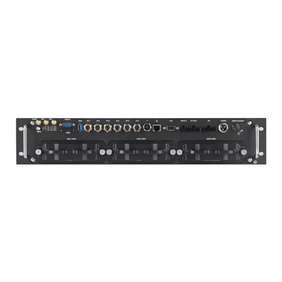
Digital Video Recorder Installation Guide Chapter 1 Panel Introduction Refer to the following figure and table for the panel description. Figure 1-1 Front Panel Table 1-1 Interface Description No. Name Description Wi-Fi antenna interfaces Reserved. M-ANT Reserved. GNSS GNSS antenna interface. Power indicator: ... - Page 8 Digital Video Recorder Installation Guide Flashing green: Network transmission is normal. Unlit: No network. Check network cable connection and IP address. HDD indicator (HDD): Solid green: HDD is working normally. Unlit: No HDD. Check HDD installation. Alarm indicator Red: Alarm occurs.
-
Page 9: Chapter 2 Installation And Connection
Digital Video Recorder Installation Guide Chapter 2 Installation and Connection Device pictures in following sections are only for reference. In condition that product pictures conflict the real device, the later prevails. Before you start: Take out the device from the package. Check the device and accessories status. Please contact us if something is missing or damaged. - Page 10 Digital Video Recorder Installation Guide Heat dissipation Install the device in the position far away from heat and ventilates well for good heat dissipation. Enough space Leave enough space for the device chassis as shown in Figure 2-2. Leave enough space for ventilation, heat dissipation, plugging or unplugging dummy HDD, etc.
-
Page 11: Install Hdd
Digital Video Recorder Installation Guide Figure 2-4 Recommended Installation Space (2) Placing angle Place the device horizontally. The other placing angles may damage the device. Fixing position All the screws in the fixing positions must be fastened tightly to avoid device falling during the vibration in driving. - Page 12 Digital Video Recorder Installation Guide Cross screwdriver. Screws (delivered with device). Figure 2-5 Tools Step 1 Wear antistatic gloves. Step 2 Insert the key and turn counterclockwise to unlock dummy HDD. Step 3 Unfasten the two screws of dummy HDD and pull dummy HDD out of device. Figure 2-6 Pull Dummy HDD out Step 4 Use cross screwdriver to loosen the two screws and remove them, and then take the dummy HDD apart.
- Page 13 Digital Video Recorder Installation Guide Figure 2-7 Take Apart Dummy HDD Step 5 Place the HDD into the dummy HDD, with the PCB facing down. Figure 2-8 Place HDD Step 6 Push the HDD along the direction shown in Figure 2-9 to connect HDD with socket of dummy HDD.
-
Page 14: Install Positioning Antenna
Digital Video Recorder Installation Guide Step 7 Use four sunk screws to fix HDD with dummy HDD. Figure 2-10 Fix HDD Step 8 Repeat step 4 to 7 to install more HDDs. Step 9 Reassemble the dummy HDD. Figure 2-11 Reassemble Dummy HDD Step 10 Plug the dummy HDD back to the device and then tighten the screws clockwise. -
Page 15: Fix Device
Digital Video Recorder Installation Guide Figure 2-12 Install Positioning Antenna on Automobile Roof Follow the instructions below in case that you need to install positioning antenna inside your automobile. Install antenna on platform under the front windshield. Windshield Antenna Figure 2-13 Install Positioning Antenna Inside Automobile ... - Page 16 Digital Video Recorder Installation Guide Figure 2-14 Fix Device...
-
Page 17: Chapter 3 Device Wiring
Digital Video Recorder Installation Guide Chapter 3 Device Wiring 3.1 Power Cord Wiring In order to ensure the safety of your automobile and device, a fuse is required for wiring of automobile power and device power. Do not connect the power cord to the device before all the cables are connected. Purpose The device starts up when your automobile ignites and shuts down after automobile is off. -
Page 18: Alarm Input Connection
Digital Video Recorder Installation Guide Device Automobile Power System DC IN DC IN Wiring of Device Point of Connection Automobile Power Switch Positive Pole Negative Pole Automobile Battery Figure 3-2 Wiring Please contact the automobile manufacturer for the connection information of starting switch. -
Page 19: Alarm Output Connection
Digital Video Recorder Installation Guide 3.3 Alarm Output Connection Follow the figure bellow to wire alarm output. n and n# are a pair of alarm output. You can connect them with a relay alarm device. When the voltage of connected alarm device exceeds the valid alarm output range, you need to connect a relay to protect alarm output. - Page 20 Digital Video Recorder Installation Guide UD11776B...
Need help?
Do you have a question about the DS-MP3516-RH and is the answer not in the manual?
Questions and answers