Advertisement
Quick Links
Advertisement

Related Manuals for HornBlasters NATHAN AIRCHIME


Summary of Contents for HornBlasters NATHAN AIRCHIME
- Page 1 Page 1 NATHAN AIRCHIME INSTALLATION MANUAL ULTIMATE NATHAN AIRCHIME KIT WARNING: To ensure the longevity of your system, reading and following these instructions are recommended. Make sure to change filters and to drain the moisture from your tank on a regular basis.
- Page 2 Page 2 HornBlasters Nathan Airchime K5LA Ultimate Kit Contents 1/2" PTC Safety 1/2" Solenoid 1/4" Brass Run Reducer Bushing Fitting Pressure Switch Blowoff Valve Valve Kit 22' Roll of 8 & Analog Pressure HornBlasters 1NM 8-Gauge Universal 40A 12v Relays...
- Page 3 • Use eye protection when operating drills or other power tools during the install. • Ensure the parking brake is engaged before you get underneath the vehicle. • Do not wire the system without the fuse holder. • Do not allow the compressor to run when the vehicle is off. www.hornblasters.com support@hornblasters.com...
-
Page 4: Recommended Tools
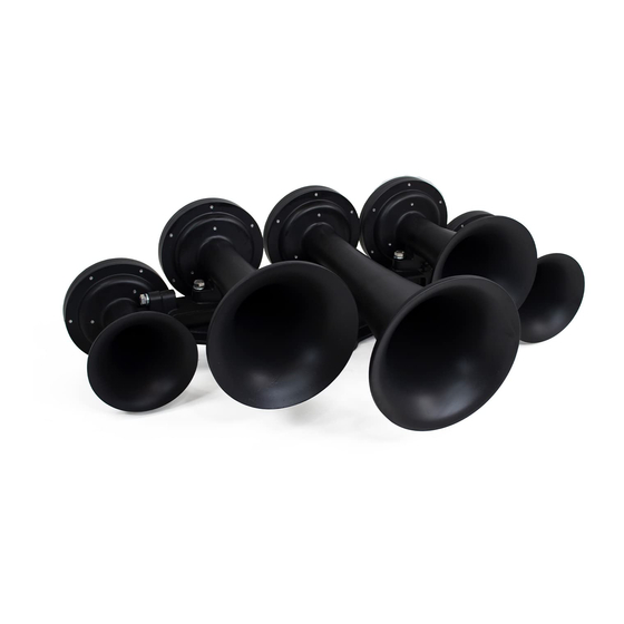
Page 4 Recommended Tools + Addons Recommended Tools • 1/2” Wrench • 10mm Wrench or Socket (Air Compressor) • 9/16” Wrench • 12mm Wrench • Hole saw (2") [Digital Gauge] • Wire Cutter / Stripper / Crimper • 1" Adjustable Wrench •... - Page 5 Page 5 Assembling the Horn Start by locating the manifold for the horn assembly. A picture of the manifold is shown below. This manifold will hold all five horn bells together in a flat configuration. The order in which the horns are assembled to the bracket does not matter.
- Page 6 Page 6 Assembling the Horn Common Horn Configurations Standard 2 Bells Reversed 3 Bells Reversed...
-
Page 7: Filter Placement
If the air filter is not relocated, the compressor will pull in water/dirt and will stop working properly. 9 out of 10 compressors that fail within the first year have pulled in water/debris from the intake. WE DO NOT WARRANTY COMPRESSORS THAT HAVE FAILED DUE TO WATER/DEBRIS BEING PULLED INTO THE INTAKE/FILTER www.hornblasters.com support@hornblasters.com... - Page 8 Page 8 Prepping The Compressors Let's set the compressors up with their respective brackets. Locate the four L-shaped compressor brackets that were packed with your air compressors. Each bracket will hold one compressor. 1. Position the air compressor mounting feet over the bracket so that the four feet line up with the slots on the bracket.
- Page 9 Page 9 This assembly show a fitting configuration if Recommended Tank Assembly you plan to mount the tank upright. If you plan to mount the tank upside down, an elbow will be need to relocate the pressure switch. When mounting upside down, the pressure switch and elbow fitting on the bottom will be reversed (switch sides) and the pressure switch is too tall to clear the...
- Page 10 Take a larger bend further away from the fitting to prevent the line from stretching the fitting out. These fittings can be re-used with the same line multiple times. If you need to remove the line, follow these steps: www.hornblasters.com support@hornblasters.com...
- Page 11 Leave these bolts loose for now, as we still need to plumb the inlet fitting into the horn. Leaving the bracket loose makes the next step much easier. Flat washer - Split Washer - Nut www.hornblasters.com support@hornblasters.com...
- Page 12 Once installed, you can confirm that the compressors/pressure switch/relay are wired properly. If the compressors do not turn on when you turn the key on the first time, double-check the key-power source that was ran to the pressure switch. support@hornblasters.com...
-
Page 13: Installation Instructions
BAR instead. Green - Connect to air pressure sensor green Left switch down: Metric (bar) wire Right switch up: voltage display ON Right switch down: voltage display Brown - Connect to air pressure sensor brown wire www.hornblasters.com sales@hornblasters.com... - Page 14 Run this line from the elbow fitting on the bottom of the tank to the inlet side of this valve. Make sure each end of the line is cut straight and flush. (refer back to page 10) Outlet Inlet support@hornblasters.com...
- Page 15 Page 15...
- Page 16 Page 16 Connecting the Train Horns to the Steering Wheel Connecting the Train Horns to a Push Button...
- Page 17 Page 17...
Need help?
Do you have a question about the NATHAN AIRCHIME and is the answer not in the manual?
Questions and answers