Table of Contents
Advertisement
Quick Links
Advertisement
Table of Contents

Subscribe to Our Youtube Channel
Related Manuals for ensto One Home EVH161B-HC000


Summary of Contents for ensto One Home EVH161B-HC000
- Page 1 Ensto One Home Installation Manual RAK131B_ENG 2022-10-14 © 2022 Ensto Chago...
-
Page 2: Table Of Contents
Contents 1. Safety instructions..........................3 2. Description of symbols........................3 3. Abbreviations............................4 4. Delivery contents........................... 4 5. Mounting instructions......................... 5 5.1. Before installation........................5 5.2. Cable entries..........................6 5.3. Wall mounting.......................... 8 6. Electrical connections........................10 6.1. Power supply.......................... 10 6.2. -
Page 3: Safety Instructions
Installation Manual 1. Safety instructions Electrically skilled person • The installation must only be done by a qualified professional. • Read this Installation Manual carefully before you start the installation work. • Obey the instructions in this Installation Manual, and make sure that the installation complies with national safety regulations, installation methods and restrictions. -
Page 4: Abbreviations
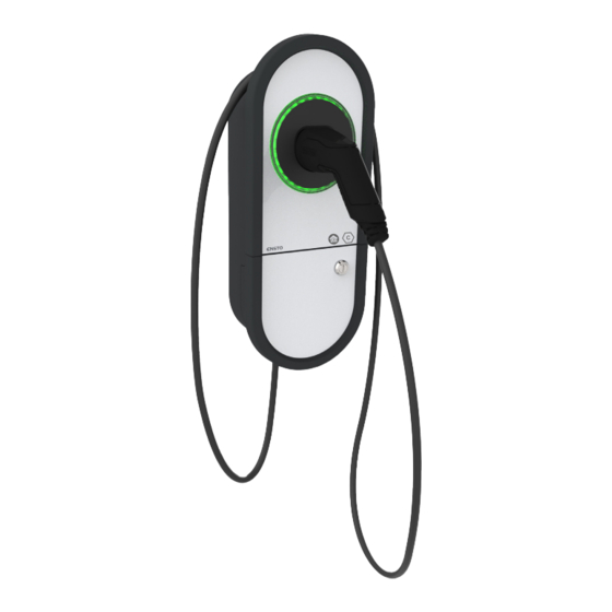
4. Delivery contents • EVH Charging station • Cable gland M32/M25 (depending on the model) • Installation Manual in English, other languages please see www.ensto.com/building-systems. • Multilingual User Guide Plug holder Plug 4-color LED indicates the charging station’s status... -
Page 5: Mounting Instructions
5. Mounting instructions 5.1. Before installation Remove the charging station from its package. Do not scratch the surface of the charging station after removal from the package. When selecting installation site, take into account the following: • The charging station is suitable for indoor and outdoor use. •... -
Page 6: Cable Entries
5.2. Cable entries • Take the cable routing into consideration when planning the installation. The supply cable can be routed into the enclosure from the rear or bottom. Default cable routing is from the bottom. • The M32 cable gland for the supply cable is pre-assembled on the bottom of the charging station. •... - Page 7 Open the necessary cable entries with a step drill bit. M16 cable entries are suitable for the RS-485 or dry contact cablings. Prepare the cable entries with suitable accessories. Remove the included cable gland from the bottom and close the cable entry with a cover plug, PMR1217.32B (accessory).
-
Page 8: Wall Mounting
5.3. Wall mounting • When selecting the installation location, make sure that the wall material is suitable and robust. The mounting surface should be flat and vertical. max. Ø5 Installation steps Use for the wall material suitable screws. Fasten the upper screw 1270 mm measured from the ground sur- face. - Page 9 TX20 Tightening torque 1,5 Nm Open the installation box hatch by removing the fastening screws (2 pcs) / unlocking the hatch lock [1]. Remove the entire installation box cover by unscrewing the fastening screws (4 pcs) [2]. Hang the charging station on the screw you attached to the wall. Attach the charging station on wall with two washers and fastening screws (not included) [3].
-
Page 10: Electrical Connections
6. Electrical connections The voltage and current ratings including cable sizes must comply with national regulations. The system dimensioning must be done by a qualified electrical designer. The default setting for the earthing system is TN network. If you connect the charging station to an IT network, you have to change the settings for the charging station accordingly. - Page 11 EVH163B-HC000 / EVH323B-HC000: • Install a residual current device (RCD type A, 30mA) and a circuit TN network breaker (MCB max. 16A or max. 32A depending on charging station model) to the supply line. In addition obey local regula- tions for the power supply line. •...
-
Page 12: Load Management Connections
EVH163B-HCR00 / EVH323B-HCR00: • A combined device with residual current circuit breaker and over TN network current protection (RCBO) is integrated. • A label set of RCBO testing instructions is included in the delivery. Attach a language specific label on the installation box hatch. •... - Page 13 Charging station External control device • Connect a dry contact module for override mode to the ter- minals 4 and 5. Remove the jumper from the pre-installed connector. Note! If you do not connect a dry contact module to the charging station, do not remove the jumper or change the related settings in the Charger Control application.
-
Page 14: Dynamic Load Management (Dlm)
6.2.1. Dynamic Load Management (DLM) You can implement dynamic load management with for this purpose compatible energy meter. The figure below shows an example how you can build up the system. • The energy meter measures the total power consumption and the actual current per phase. If some other load over the set maximum current for load management is added when charging is ongoing, the charger will decrease the charging current. -
Page 15: Load Management In Override Mode
6.2.2. Load Management in Override mode Ensto One charging stations are compatible with a variety of home control systems. The Legrand group has a wide assortment of devices for home control systems. The figure below shows an example how you can build up load management with Netatmo Connect. -
Page 16: Control Of Charging In Override Mode
6.2.3. Control of charging in Override mode The charging events can be controlled by a dry contact module. The figure below shows an example how you can build up the override control of charging with a timer, switch, relay or similar. When the dry contact is closed, the charging station gets power and can charge the connected vehicle. -
Page 17: Technical Information
7. Technical information Electrical Connections EVH161B-HC000 EVH321B-HC000 EVH161B-HCR00 EVH321B-HCR00 Nominal supply 1-ph, 230 VAC voltage Nominal frequency AC 50 Hz Charging current max. 1x16 A 1x32 A 1x16 A 1x32 A Charging power max. 3600 W 7400 W 3600 W 7400 W Depends on the LED settings: Idle power loss... - Page 18 EVH161B-HC000 EVH321B-HC000 EVH161B-HCR00 EVH321B-HCR00 User Interface EVH163B-HC000 EVH323B-HC000 EVH163B-HCR00 EVH323B-HCR00 Connection to vehicle Fixed cable, length 5m 4-color LED: Charging status Green = Ready / Blue = Charging / Red = Error / indication Yellow = Internal maintenance Free access or authorization mode Use access Settings done via mobile application EVH161B-HC000...
-
Page 19: Code Key
Not available RCBO Fixed charging cable Type 2 socket (T2) Type 2 Shutter socket (T2S) Home Apartment Product version - “B” load management 1-phase 3-phase Max. charging current 16A Max. charging current 32A Ensto One RAK131B_ENG / 2022-10-14 19 / 24... -
Page 20: Installation / Commissioning Checklist
9. Installation / Commissioning checklist Introduction Examine the mechanical and electrical installation in accordance with this checklist to make sure that the charging station is properly installed. Checking the Installation Examine the visual, mechanical and electrical installation when the charging station is un- powered. -
Page 21: Dimension Drawing
10. Dimension drawing 11. Troubleshooting Charging station is off, no lights on Issue Corrective action Mains voltage does not exist in supply connec- Make sure that the supply conductors are properly tors (L1, L2, L3). connected. Make sure that there is power available. The circuit breaker QF1 is off Turn the QF1 on. -
Page 22: Charger Control Application
In this chapter is described the settings, which are only allowed for qualified professionals. • For additional instructions please see the User Guide for the Ensto One Home charging station. Note! Do not change the settings while charging is in progress. -
Page 23: Connected Phases
12.2.3. Connected phases Select the phase the charging station is connected to. 12.2.4. Phase rotation (only 3-phase chargers) Selection of phase rotation is only informative and does not affect the charging station’s operation. 12.2.5. Earthing System The default setting for power supply is TN network. If you connect the charger to an IT network, you have to change settings for the charger accordingly. - Page 24 Ensto Chago Oy Ensio Miettisen katu 2, P.O. Box 77 FIN-06101 Porvoo, Finland Tel. +358 204 76 21 www.ensto.com/building-systems...
Need help?
Do you have a question about the One Home EVH161B-HC000 and is the answer not in the manual?
Questions and answers