ensto One Home Installation Manual
Hide thumbs
Also See for One Home:
- User manual (44 pages) ,
- Installation manual (24 pages) ,
- User manual (84 pages)
Table of Contents
Advertisement
Quick Links
Advertisement
Table of Contents

Related Manuals for ensto One Home


Summary of Contents for ensto One Home
- Page 1 Ensto One Home Installation Manual RAK131_ENG 6.4.2021 © 2020 Ensto...
-
Page 2: Table Of Contents
11. EVH163-HCR00 / EVH323-HCR00 internal circuit example......20 12. Dimension drawing..................21 13. Troubleshooting....................21 14. Ensto Charger Control Application..............22 14.1. Installer menu in the Ensto Charger Control Application....22 14.1.1. Self test....................22 14.1.2. Update device firmware..............23 14.1.3. Maximum charging current.............. 23 14.1.4. -
Page 3: Safety Instructions
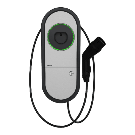
Do not switch on the power supply before the installation work is completed. 2. Delivery contents • EVH Charger • Cable gland M32/M25 (depending on the model) • Installation Manual in English, other languages please see www.ensto.com. • Multilingual User Guide Plug holder Plug 4-color LED indicates the charger’s status Fixed cable... -
Page 4: Mounting Instructions
3. Mounting instructions 3.1. Before installation Remove the charger from its package. Do not scratch the surface of the charger after removal from the package. When selecting installation site, take into account the following: • The charger is suitable for indoor and outdoor use. •... -
Page 5: Cable Entries
3.2. Cable entries • Take the cable routing into consideration when planning the installation. The supply cable can be routed into the enclosure from the rear or bottom. Default cable routing is from the bottom. • The M32 cable gland for the supply cable is pre-assembled on the bottom of the charger. •... - Page 6 Open the needed cable entries with a step drill bit. Prepare the cable entries with suitable accessories. Remove the included cable gland from the bottom and close the cable entry with a cover plug, PMR1217.32B (accessory). Assemble the base and insert. Assemble also the installation box cover, if electrical cables are installed in a separate session.
-
Page 7: Wall Mounting
3.3. Wall mounting • When selecting the installation location, make sure that the wall material is suitable and robust. The mounting surface should be flat and vertical. max. Ø5 Installation steps Use for the wall material suitable screws. Fasten the upper screw 1270 mm measured from the ground surface. - Page 8 TX20 Tightening torque 1,5 Nm Open the installation box hatch by removing the fastening screws (2 pcs) / unlocking the hatch lock [1]. Remove the entire installation box cover by unscrewing the fastening screws (4 pcs) [2]. Hang the charger on the screw you attached to the wall. Secure the charger on wall with two washers and fastening screws (not included) [3].
-
Page 9: Power Supply
IT network, you have to change the settings for the charger accordingly. You can change the setting with the Ensto Charger Control Application. Please see the chapter 14. Ensto Charger Control Application on pages 22 - 23. EVH161-HC000 / EVH321-HC000: •... - Page 10 EVH163-HC000 / EVH323-HC000: • Install a residual current device (RCD type A, 30mA) and a circuit breaker (MCB max. 16A or max. 32A depending on charger model) to the supply line. In addition follow local regu- lations for the power supply line. •...
- Page 11 EVH161-HCR00 / EVH321-HCR00: • A combined device with residual current circuit breaker and over current protection (RCBO) is integrated. • A label set of RCBO testing instructions is included in the delivery. Attach a language spe- cific label on the installation box hatch. •...
- Page 12 EVH163-HCR00 / EVH323-HCR00: • A combined device with residual current circuit breaker and over current protection (RCBO) is integrated. • A label set of RCBO testing instructions is included in the delivery. Attach a language spe- cific label on the installation box hatch. •...
-
Page 13: Technical Information
5. Technical information Electrical Connections EVH161-HC000 EVH321-HC000 EVH161-HCR00 EVH321-HCR00 Nominal supply 1-ph, 230 VAC voltage Nominal frequency AC 50 Hz Charging current max. 1x16 A 1x32 A 1x16 A 1x32 A Charging power max. 3600 W 7400 W 3600 W 7400 W L1, N, PE L1, N, PE... - Page 14 EVH161-HC000 EVH321-HC000 EVH161-HCR00 EVH321-HCR00 User Interface EVH163-HC000 EVH323-HC000 EVH163-HCR00 EVH323-HCR00 Connection to vehicle Fixed cable, length 5m 4-color LED: Charging status Green = Ready / Blue = Charging / Red = Error / indication Yellow = Internal maintenance Free access Use access Mobile application EVH161-HC000...
-
Page 15: Code Key
Not available MID class kWH meter Not available RCBO Fixed charging cable Type 2 socket (T2) Type 2 Shutter socket (T2S) Home Apartment 1-phase 3-phase Max. charging current 16A Max. charging current 32A Ensto One RAK131_ENG / 6.4.2021 15 / 24... -
Page 16: Installation / Commissioning Checklist
7. Installation / Commissioning checklist Introduction Check the mechanical and electrical installation according this checklist in order to make sure that the charger is properly installed. Checking the Installation Go through the visual, mechanical and electrical installation when the charger is un- powered. -
Page 17: Evh161-Hc000 / Evh321-Hc000 Internal Circuit Example
8. EVH161-HC000 / EVH321-HC000 internal circuit example J1 J16 LED Board A1 EVI200 Supply Cu 2.5–10 mm² Fixed charging cable Note! All signal wires must be at a sufficient distance from the power wires or protected with insulating shield / plastic spiral. RAK131_ENG / 6.4.2021 17 / 24... -
Page 18: Evh163-Hc000 / Evh323-Hc000 Internal Circuit Example
9. EVH163-HC000 / EVH323-HC000 internal circuit example Fixed charging cable Supply Cu 2.5–10 mm² Note! All signal wires must be at a sufficient distance from the power wires or protected with insulating shield / plastic spiral. RAK131_ENG / 6.4.2021 18 / 24... -
Page 19: Evh161-Hcr00 / Evh321-Hcr00 Internal Circuit Example
10. EVH161-HCR00 / EVH321-HCR00 internal circuit example J1 J16 LED Board A1 EVI200 Supply Cu 2.5–10 mm² Note! All signal wires must be at a sufficient Fixed charging cable distance from the power wires or protected with insulating shield / plastic spiral. RAK131_ENG / 6.4.2021 19 / 24... -
Page 20: Evh163-Hcr00 / Evh323-Hcr00 Internal Circuit Example
11. EVH163-HCR00 / EVH323-HCR00 internal circuit example Fixed charging cable Supply Cu 2.5–10 mm² Note! All signal wires must be at a sufficient distance from the power wires or protected with insulating shield / plastic spiral. RAK131_ENG / 6.4.2021 20 / 24... -
Page 21: Dimension Drawing
12. Dimension drawing 13. Troubleshooting Charging station is off, no lights on Issue Corrective action Mains voltage does not exist in supply Ensure proper power supply. connectors (L1, L2, L3). The circuit breaker QF1 is off Turn the QF1 on. (EVH...-HCR00). -
Page 22: Ensto Charger Control Application
• In this chapter is described the installer menu in the application. • For additional instructions please see the User Guide for the Ensto One Home charger. 14.1. Installer menu in the Ensto Charger Control Application WARNING Danger of electric shock! Risk of fire! •... -
Page 23: Update Device Firmware
14.1.2. Update device firmware This menu is visible if a firmware update is available. We recommend that you update the firmware to ensure that the charger works properly. 14.1.3. Maximum charging current The setting of the maximum charging current must comply with the system di- mensioning. - Page 24 Ensto Chago Oy Ensio Miettisen katu 2, P.O. Box 77 FIN-06101 Porvoo, Finland Tel. +358 204 76 21...
Need help?
Do you have a question about the One Home and is the answer not in the manual?
Questions and answers