Table of Contents
Advertisement
Available languages
Available languages
Quick Links
Cod. 998990
12/2015
FOX DRIVE PLUS
FOX DRIVE PLUS DT
MANUALE D'USO E MANUTENZIONE
USE AND MAINTENANCE MANUAL
MANUEL D'UTILISATION ET D'ENTRETIEN
BEDIENUNGS-UND WARTUNGSANLEITUNG
MANUAL DE USO Y MANTENIMIENTO
Instrucciones originales
Istruzioni originali
Original instruction
Notices originales
Originalanleitung
Advertisement
Table of Contents

Related Manuals for Checchi & Magli FOX DRIVE PLUS


Summary of Contents for Checchi & Magli FOX DRIVE PLUS
- Page 1 FOX DRIVE PLUS FOX DRIVE PLUS DT MANUALE D'USO E MANUTENZIONE USE AND MAINTENANCE MANUAL MANUEL D’UTILISATION ET D’ENTRETIEN BEDIENUNGS-UND WARTUNGSANLEITUNG MANUAL DE USO Y MANTENIMIENTO Istruzioni originali Original instruction Notices originales Originalanleitung Instrucciones originales Cod. 998990 12/2015...
- Page 3 Demolizione della macchina operatrice ....................42 Descrizione comandi ............................ 28 Descrizione generale ............................3 Dichiarazione di conformità ..........................7 Dimensioni d’ingombro (FOX DRIVE PLUS) .....................5 Dimensioni d’ingombro (FOX DRIVE PLUS DT) ..................6 Dimensioni piantina ............................7 Disimballo e montaggio ..........................16 Distanza interpianta ............................7 Documentazione allegata ..........................2 Elementi principali (FOX DRIVE PLUS) ......................3...
- Page 4 Segnali di sicurezza e informazione ......................9 Sistemazione sedile e cassetta portapiante ..................30 Sollevamento (FOX DRIVE PLUS) ......................14 Sollevamento (FOX DRIVE PLUS DT) ......................15 Sommario ................................III Sostituzione catena ruota motrice ......................39 Sostituzione catena ruota motrice (Rapid Shift) ................. 40 Sostituzione catena unità...
- Page 5 INFORMAZIONI GENERALI Scopo del manuale Il manuale è stato realizzato dal costruttore per fornire le Per evidenziare alcune parti di testo, rilevanti ai fini della informazioni necessarie e i criteri da seguire a tutti colo- sicurezza o per indicare informazioni importanti, sono ro che interagiscono con la macchina operatrice specifi- stati adottati alcuni simboli il cui significato è...
- Page 6 INFORMAZIONI GENERALI Documentazione allegata Assieme a questo manuale, al cliente viene rilasciata la sono considerate in questo manuale. documentazione indicata. - Dichiarazione “CE” di conformità della macchina ope- Le istruzioni d’uso e manutenzione dell’eventuale grup- ratrice. po opzionale a corredo della macchina operatrice non Modalità...
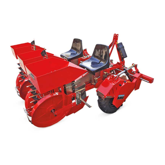
- Page 7 Elementi principali (FOX DRIVE PLUS) L’illustrazione raffigura la macchina operatrice con due unità di trapianto. UN41 0619MN A) Struttura per il collegamento all’attacco a tre punti...
- Page 8 INFORMAZIONI TECNICHE Elementi principali (FOX DRIVE PLUS DT) L’illustrazione raffigura la macchina operatrice con due unità di trapianto. UN41 0620MN A) Struttura per il collegamento all’attacco a tre punti F) Distributore della trattrice (doppio telaio) G) Ruote costipatrici B) Ruota motrice...
- Page 9 INFORMAZIONI TECNICHE Dimensioni d’ingombro (FOX DRIVE PLUS) FOX DRIVE PLUS/1 FOX DRIVE PLUS/2 FOX DRIVE PLUS/3 FOX DRIVE PLUS/4 FOX DRIVE PLUS/5 FOX DRIVE PLUS/6 UN41 0621MN Caratteristiche tecniche FOX DRIVE PLUS FOX DRIVE FOX DRIVE FOX DRIVE FOX DRIVE...
- Page 10 INFORMAZIONI TECNICHE Dimensioni d’ingombro (FOX DRIVE PLUS DT) FOX DRIVE PLUS DT/2 FOX DRIVE PLUS DT/3 FOX DRIVE PLUS DT/4 FOX DRIVE PLUS DT/5 FOX DRIVE PLUS DT/6 FOX DRIVE PLUS DT/7 UN41 0622MN Caratteristiche tecniche FOX DRIVE PLUS DT...
- Page 11 FOX DRIVE PLUS/1 - FOX DRIVE PLUS/2 - FOX DRIVE PLUS/3 - FOX DRIVE PLUS/4 - FOX DRIVE PLUS/5 - FOX Budrio DRIVE PLUS/6 - FOX DRIVE PLUS DT/2 - FOX DRIVE PLUS DT/3 - FOX DRIVE PLUS DT/4 - FOX DRIVE PLUS CHECCHI &...
- Page 12 INFORMAZIONI TECNICHE Protezioni RAPID SHIFT ATTENZIONE Non usare la macchina senza i carter di protezione. La macchina operatrice è dotata di protezioni degli or- gani di trasmissione per evitare infortuni causati dal con- tatto involontario con gli elementi in movimento. L’illustrazione raffigura i carter installati a protezione de- gli organi in movimento.
- Page 13 Verificare che le targhe siano leggibili; in caso contra- rio pulirle e se danneggiate sostituirle applicandole nella posizione originale. FOX DRIVE PLUS FOX DRIVE PLUS DT BUDR O ( O) BU RIO BO) UN41 0624MN A) Targa di pericolo: leggere il manuale d’uso e manu- G) Targa di informazione: indica il senso di rotazione tenzione prima di utilizzare la macchina operatrice.
- Page 14 Porta-vassoi trasversale a 2 ripiani cm 400 Kit dischi rincalzatori Ø 410 mm Kit vomeri rincalzatori posteriori Vomere a versoi registrabili Disco davanti al vomere FOX DRIVE PLUS Telaio sfilabile idraulico Microgranulatore 1 fila - ruota trasmissione Microgranulatore 2 file - ruota trasmissione...
- Page 15 INFORMAZIONI TECNICHE Rumore L’impiego delle trapiantatrici non comporta un aumento Consultare il manuale del costruttore della trattrice per significativo del livello di pressione sonora della trattrice valutare i dispositivi di protezione individuale adeguati a cui viene collegata la trapiantatrice stessa. da adottare a protezione dell’udito.
- Page 16 INFORMAZIONI SULLA SICUREZZA Leggere attentamente questo manuale prima di pro- In caso di avaria, evitare di eseguire interventi di ripa- cedere alle operazioni di impiego, manutenzione o razione sul luogo se non si è sicuri di operare in am- altri interventi sulla macchina operatrice. biente idoneo e se non si dispone delle attrezzature adeguate;...
- Page 17 FOX DRIVE FOX DRIVE FOX DRIVE PLUS/1 PLUS/2 PLUS/3 PLUS/4 PLUS/5 PLUS/6 Colli n° Dimensioni indicative dell’imballo FOX DRIVE PLUS DT FOX DRIVE FOX DRIVE FOX DRIVE FOX DRIVE FOX DRIVE FOX DRIVE PLUS DT/2 PLUS DT/3 PLUS DT/4 PLUS DT/5...
- Page 18 I punti di presa per il sollevamento valgono per tutti i Le operazioni di sollevamento devono essere effettuate modelli di FOX DRIVE PLUS. con mezzi adeguati al carico da sollevare e da personale UN41 0626MN Procedere come descritto.
- Page 19 Le operazioni di sollevamento devono essere effettuate I modelli FOX DRIVE PLUS DT/5 - FOX DRIVE PLUS con mezzi adeguati al carico da sollevare e da personale DT/6 - FOX DRIVE PLUS DT/7 devono essere sollevati...
- Page 20 L’illustrazione raffigura sommariamente lo schema di montaggio della macchina operatrice. FOX DRIVE PLUS/1 FOX DRIVE PLUS/2 FOX DRIVE PLUS/3 FOX DRIVE PLUS/4...
- Page 21 INFORMAZIONI SULLA MOVIMENTAZIONE E INSTALLAZIONE L’illustrazione raffigura sommariamente lo schema di montaggio della macchina operatrice divisa in due gruppi. FOX DRIVE PLUS DT/2 FOX DRIVE PLUS DT/3 FOX DRIVE PLUS DT/4 FOX DRIVE PLUS DT/5 FOX DRIVE PLUS DT/6 FOX DRIVE PLUS DT/7...
- Page 22 INFORMAZIONI SULLE REGOLAZIONI Raccomandazioni di sicurezza per le regolazioni Gli interventi di regolazione devono essere effettuati accensione rimossa e adottare tutti gli accorgimenti su terreno pianeggiante e compatto, con la trattrice necessari per operare in sicurezza. spenta, il freno di stazionamento tirato, la chiave di Regolazione tensione catena distributore Per questa operazione procedere come descritto.
- Page 23 INFORMAZIONI SULLE REGOLAZIONI Regolazione chiusura pinze La regolazione serve per anticipare e ritardare la chiusu- ra delle pinze. Eseguire le operazioni descritte. 1) Allentare la vite (A) da entrambi i lati delle guide (B). 2) Alzare le guide in modo uguale per anticipare la chiu- sura della pinza.
- Page 24 INFORMAZIONI SULLE REGOLAZIONI 12) Avvitare la vite (A). Effettuare le stesse operazioni per sostituire i vomeri nel- 13) Montare allo stesso modo l’altra cassetta portapian- le altre unità di trapianto. Regolazione carico del ruotino Procedere come descritto. - Ruotare il pomello (A) in senso orario per aumentare il carico del ruotino (B) sul terreno.
- Page 25 INFORMAZIONI SULLE REGOLAZIONI Regolazione del disinnesto automatico di sicurezza Il disinnesto automatico ha lo scopo di preservare gli organi di trasmissione da sovraccarichi (ad esempio in caso di bloc- caggio del distributore ecc.). Il dispositivo, installato su ogni unità di trapianto, è...
- Page 26 INFORMAZIONI SULLE REGOLAZIONI Regolazione interpianta La distanza tra una pianta e quella successiva è deter- minata dal numero di denti dei pignoni installati e dalla quantità di pinze del distributore. Possono essere montate diverse serie di pignoni al fine di ottenere la distanza di interpianta richiesta. La medesima sostituzione dei pignoni deve essere effet- tuata su tutte le unità...
- Page 27 INFORMAZIONI SULLE REGOLAZIONI ALLESTIMENTO - 15 PINZE ALLESTIMENTO - 20 PINZE Distanza interpianta N° denti pignoni Distanza interpianta N° denti pignoni inches inches 7 - 1/8 5 - 1/8 8 - 1/4 6 - 1/4 9 - 1/16 6 - 3/4 9 - 7/8 7 - 1/2 8 - 1/4...
- Page 28 INFORMAZIONI SULLE REGOLAZIONI ALLESTIMENTO - 2 PINZE RAPID SHIFT DX Distanza interpianta N° denti pignoni inches z 1 z 2 z 3 z 4 z 5 z 6 68 - 7/8 74 - 7/8 16 14 17 17 82 - 3/4 86 - 5/8 94 - 1/2 98 - 1/2...
- Page 29 INFORMAZIONI SULLE REGOLAZIONI ALLESTIMENTO - 5 PINZE RAPID SHIFT SX Distanza interpianta N° denti pignoni inches z 1 z 2 z 3 z 4 z 5 z 6 25 - 3/16 27 - 1/2 16 14 17 17 33 - 1/8 34 - 5/8 37 - 3/8 39 - 3/8...
- Page 30 INFORMAZIONI SULLE REGOLAZIONI ALLESTIMENTO - 15 PINZE RAPID SHIFT DX Distanza interpianta N° denti pignoni inches z 1 z 2 z 3 z 4 z 5 z 6 7 - 1/8 8 - 1/4 9 - 1/16 16 14 17 17 9 - 7/8 11 - 3/4 12 - 5/8...
- Page 31 INFORMAZIONI SULLE REGOLAZIONI ALLESTIMENTO - 20 PINZE RAPID SHIFT SX Distanza interpianta N° denti pignoni inches z 1 z 2 z 3 z 4 z 5 z 6 5 - 1/8 6 - 1/4 6 - 3/4 16 14 17 17 7 - 1/2 8 - 1/4 8 - 5/8...
- Page 32 INFORMAZIONI SULL’USO Raccomandazioni di sicurezza per l’uso Per prevenire il rischio di infortunio leggere attenta- Accertare che non vi siano persone o animali nella mente le prescrizioni di sicurezza riportate nel capi- zona di manovra e di lavoro della macchina. tolo “3”.
- Page 33 INFORMAZIONI SULL’USO Attacco e distacco della macchina operatrice dalla trattrice ATTENZIONE ATTENZIONE Il collegamento della macchina operatrice alla trattri- Collegare la macchina operatrice solo ad una trat- ce è uno dei momenti più rischiosi poiché potrebbe ri- trice di adeguata potenza e provvista di sollevatore chiedere la necessità...
- Page 34 INFORMAZIONI SULL’USO Sistemazione sedile e cassetta portapiante Una scorretta posizione di lavoro affatica l’operatore che ma dell’inizio del lavoro, regolare e bloccare il sedile nel- potrebbe compiere operazioni non corrette, per cui, pri- la posizione di massimo comfort. UN41 0643MN Procedere come descritto.
- Page 35 INFORMAZIONI SULL’USO Cambio rapporto trasmissione (Rapid Shift) ATTENZIONE INFORMAZIONE Spegnere il motore della trattrice, disinserire e custo- Il cambio del rapporto della trasmissione ha lo scopo dire la chiave di accensione per prevenire il pericolo di ottenere l’interpianta richiesto. di infortunio durante la fase del cambio del rapporto Fare riferimento al capitolo “Regolazione interpian- di trasmissione.
- Page 36 INFORMAZIONI SULL’USO Modalità di trapianto La messa a dimora delle piantine deve essere effettuata Non operare su terreni molto soffici, molto compatti o su terreni preventivamente sminuzzati con erpici o zap- molto bagnati per non pregiudicare la buona qualità di patrici e leggermente compattati in superficie.
- Page 37 “Sollevamento FOX DRIVE Il punto di congiunzione delle rampe con il pianale crea un dosso pericoloso per cui si deve operare con PLUS” a pagina 14 o “Sollevamento FOX DRIVE PLUS DT” estrema cautela in prossimità di tale punto. a pagina 15.
- Page 38 INFORMAZIONI SULL’USO Circolazione su strade pubbliche ATTENZIONE È vietato trasportare persone e/o cose sulla macchina operatrice. Prima di mettersi su strade togliere le piantine dai portapiantine e pulire accuratamente gli organi lavoranti e i pneumatici dai residui di terra. Nel trasferimento del complesso macchi- na operatrice-trattrice osservare le pre- scrizioni del codice della strada.
- Page 39 INFORMAZIONI SULLA MANUTENZIONE Raccomandazioni di sicurezza per la manutenzione Gli interventi di manutenzione devono essere ef- Per gli interventi straordinari (non compresi in que- fettuati su terreno pianeggiante, compatto, con la sto manuale) occorre disporre di un’officina azienda- trattrice spenta, il freno di stazionamento tirato, la le avente le caratteristiche indicate dalla legislazione chiave di accensione rimossa e adottando tutti gli ac- vigente in materia (attrezzature adeguate, personale...
- Page 40 INFORMAZIONI SULLA MANUTENZIONE Inconvenienti, cause, rimedi L’elenco riporta alcuni inconvenienti e i relativi rimedi che possono capitare durante la fase di lavoro. Inconveniente Probabile causa Rimedio La profondità di trapianto non è Eseguire la regolazione (vedere corretta “Regolazione profondità di trapianto”) La piantina a dimora è...
- Page 41 INFORMAZIONI SULLA MANUTENZIONE Schema punti di lubrificazione Lubrificare gli organi raffigurati nei tempi e nei modi in- Usare grasso universale per autotrazione di macchinari dicati. agricoli e industriali, idrorepellente con punto di goccia Prima di effettuare la lubrificazione pulire accuratamen- 180°.
- Page 42 INFORMAZIONI SULLE SOSTITUZIONI Raccomandazioni di sicurezza per le sostituzioni La sostituzione di componenti usurati o danneggiati le avente le caratteristiche indicate dalla legislazione deve essere effettuata con ricambi originali. vigente in materia (attrezzature adeguate, personale Per gli interventi straordinari (non compresi in que- idoneo, ecc.), altrimenti occorre rivolgersi ad officine sto manuale) occorre disporre di un’officina azienda- autorizzate.
- Page 43 INFORMAZIONI SULLE SOSTITUZIONI Sostituzione catena ruota motrice UN41-0510MM Per questa operazione procedere come descritto. Montare una nuova catena. Montare il carter (D). Azionare la leva (E) per sollevare la ruota con lo sco- Avvitare i pomelli (C). po di ridurre la tensione della catena. 10) Montare il carter (B).
- Page 44 INFORMAZIONI SULLE SOSTITUZIONI Sostituzione catena ruota motrice (Rapid Shift) UN41-0511MM Per questa operazione procedere come descritto. 4) Muovere il tenditore (D) e rimuovere la catena (E). 1) Azionare la leva (C) per sollevare la ruota con lo sco- PRUDENZA po di ridurre la tensione della catena. 2) Svitare i dadi (A).
- Page 45 INFORMAZIONI SULLE SOSTITUZIONI Procedere come descritto. Rimuovere la catena dai pignoni. Montare una nuova catena. Svitare i dadi (C). 10) Montare la maglia di giunzione (F). Rimuovere il carter (D). 11) Montare la catena sul tendicatena. Svitare i dadi (A). Rimuovere il carter (B).
- Page 46 INFORMAZIONI SULLE SOSTITUZIONI Sostituzione vomere UN41 0651MN Eseguire le operazioni descritte. 5) Rimuovere il vomere (D). 6) Posizionare il nuovo vomere. 1) Allentare i dadi (A). 7) Infilare le viti (C). 2) Svitare i dadi (B). 8) Avvitare i dadi (B). 3) Sfilare le viti (C).
- Page 47 Hitching and unhitching the work vehicle to and from the tractor ..........29 Information and safety signs .........................9 Lifting (FOX DRIVE PLUS) ..........................14 Lifting (FOX DRIVE PLUS DT) ........................15 Lubrication diagram ............................37 Main parts (FOX DRIVE PLUS) ........................3...
- Page 48 Main parts (FOX DRIVE PLUS DT) .........................4 Maintenance interval schedule ......................... 35 Manufacturer and machine identification details .................1 Night-time work or poor visibility conditions ..................33 Noise ................................... 11 Nuts and bolts tightening torques chart ....................36 Optional accessories ............................. 10 Overall dimensions (FOX DRIVE PLUS) .......................5...
- Page 49 GENERAL INFORMATION Aim of the manual This instruction manual is produced by the manufactur- To highlight certain parts of the manual’s contents er to provide all those who have dealings with the work deemed important for safety or information reasons the vehicle stated on the cover with all the necessary infor- following symbols have been used, whose meanings are mation and criteria to apply for its use.
- Page 50 GENERAL INFORMATION Annexed documentation Along with this handbook, the customer is given the are not considered in this manual. documentation specified. - EC Declaration of conformity for the work vehicle. The instructions for use and maintenance of any optional units that may be provided with the work vehicle which Assistance request procedure All requests for technical assistance must be made to the Whenever making requests for technical assistance con-...
- Page 51 The moving parts are driven by the works vehicle’s driv- featured and number of grippers in the dispensing unit. Main parts (FOX DRIVE PLUS) The illustration shows the work vehicle with two planting units. UN41 0619MN...
- Page 52 TECHNICAL INFORMATION Main parts (FOX DRIVE PLUS DT) The illustration shows the work vehicle with two planting units. UN41 0620MN A) Structure for attaching to the three-point hitch on a F) Dispenser tractor (double frame) G) Packing wheels B) Driving wheel...
- Page 53 TECHNICAL INFORMATION Overall dimensions (FOX DRIVE PLUS) FOX DRIVE PLUS/1 FOX DRIVE PLUS/2 FOX DRIVE PLUS/3 FOX DRIVE PLUS/4 FOX DRIVE PLUS/5 FOX DRIVE PLUS/6 UN41 0621MN Technical characteristics FOX DRIVE PLUS FOX DRIVE FOX DRIVE FOX DRIVE FOX DRIVE...
- Page 54 TECHNICAL INFORMATION Overall dimensions (FOX DRIVE PLUS DT) FOX DRIVE PLUS DT/2 FOX DRIVE PLUS DT/3 FOX DRIVE PLUS DT/4 FOX DRIVE PLUS DT/5 FOX DRIVE PLUS DT/6 FOX DRIVE PLUS DT/7 UN41 0622MN Technical characteristics FOX DRIVE PLUS DT...
- Page 55 EN 13857, on machine safety. FOX DRIVE PLUS/1 - FOX DRIVE PLUS/2 - FOX DRIVE PLUS/3 - FOX DRIVE PLUS/4 - FOX DRIVE PLUS/5 - FOX Budrio DRIVE PLUS/6 - FOX DRIVE PLUS DT/2 - FOX DRIVE PLUS DT/3 - FOX DRIVE PLUS DT/4 - FOX DRIVE PLUS CHECCHI &...
- Page 56 TECHNICAL INFORMATION Guards RAPID SHIFT WARNING Never use the machine without the safety guards. The work vehicle is fitted with guards covering the trans- mission components to prevent accidental contact with the moving parts. The picture shows the casings fitted to protect the mov- ing parts.
- Page 57 - if they are damaged - replace them, applying the new ones in the same place as the old ones. FOX DRIVE PLUS FOX DRIVE PLUS DT BUDR O ( O) BU RIO BO) UN41 0624MN A) Hazard plate: read the use and maintenance manual to which the plate is applied, showing the direction before using the work vehicle.
- Page 58 Transversal 2-shelf tray holder (shelf size: cm 400) Ridging disks kit (Ø 410 mm) Kit of rear ridger ploughs Ploughshare with adjustable mouldboards Disc in front of the ploughshare FOX DRIVE PLUS Hydraulic removable frame Microgranulator 1 row - drive wheel Microgranulator 2 rows - drive wheel...
- Page 59 TECHNICAL INFORMATION Noise The use of the planting machine does not mean a signifi- Check the tractor manufacturer’s manual to decide cant increase in the noise levels of the tractor to which which PPE to adopt for hearing protection. the planting machine is hitched. Residual risks During the design and construction stag- es, the manufacturer has focused particu-...
- Page 60 SAFETY INFORMATION Read this manual carefully before proceeding with In the event of a failure, do not carry out any repairs any operations concerning use, maintenance or oth- on site unless you are certain that the area you are in er work on the work vehicle.
- Page 61 FOX DRIVE FOX DRIVE FOX DRIVE PLUS/1 PLUS/2 PLUS/3 PLUS/4 PLUS/5 PLUS/6 Parcels n° Indicative packaging dimensions FOX DRIVE PLUS DT FOX DRIVE FOX DRIVE FOX DRIVE FOX DRIVE FOX DRIVE FOX DRIVE PLUS DT/2 PLUS DT/3 PLUS DT/4 PLUS DT/5...
- Page 62 Check the parcel weight stated on the packing itself. The illustration shows the harnessing points and lifting procedure. UN41 0579GN Lifting (FOX DRIVE PLUS) ised personnel in order to safeguard their own safety WARNING and that of the other people involved in the operations.
- Page 63 Lifting operations must be carried out using suitable The FOX DRIVE PLUS DT/5 - FOX DRIVE PLUS DT/6 - means for the load to be lifted, by qualified and author- FOX DRIVE PLUS DT/7 models must always be hoisted...
- Page 64 The packing materials must be appropriately disposed during unpacking and installation. of or recycled in accordance with the laws in force. The illustration provides a rough outline of the work vehicle assembly. FOX DRIVE PLUS/1 FOX DRIVE PLUS/2 FOX DRIVE PLUS/3 FOX DRIVE PLUS/4...
- Page 65 INFORMATION CONCERNING HANDLING AND INSTALLATION The illustration provides a rough outline of the work vehicle assembly divided into two units. FOX DRIVE PLUS DT/2 FOX DRIVE PLUS DT/3 FOX DRIVE PLUS DT/4 FOX DRIVE PLUS DT/5 FOX DRIVE PLUS DT/6...
- Page 66 ADJUSTMENT INFORMATION Safety advice for the adjustments Maintenance and adjustment work must be car- engaged, ignition key removed, and adopting all the ried out with the work vehicle on flat and compact necessary safety measures required to work safely. ground, with the tractor engine off, parking brake Adjustment of dispenser chain tension For this operation, proceed as outlined below.
- Page 67 ADJUSTMENT INFORMATION Gripper closure adjustment The purpose of the adjusting procedure is to anticipate and delay gripper closure. Carry out the operations described. 1) Loosen the screw (A) on both sides of the runners (B). 2) Lift the runners applying equal force to anticipate gripper closure.
- Page 68 ADJUSTMENT INFORMATION 12) Tighten the screw (A). Repeat the same procedure to replace the ploughshares 13) Position the other seedling holder in the same way. of the other transplanting units. Adjusting the small wheel load Proceed as outlined below. - Turn the knob (A) clockwise to increase the small wheel (B) load on the ground.
- Page 69 ADJUSTMENT INFORMATION Adjusting the automatic safety release function The automatic release is designed to protect the transmission components from overloads (e.g. if the dispenser jams, etc.). The device, installed on every planting unit, is already set by the manufacturer during the testing stage, but can be ad- justed by the user according to require- ments.
- Page 70 ADJUSTMENT INFORMATION Adjusting the plant spacing The distance between one seedling and the next is de- termined by the number of teeth of the pinions installed and the number of grippers fitted to the dispenser. A series of pinions may be fitted to ensure the required plant spacing is obtained.
- Page 71 ADJUSTMENT INFORMATION EQUIPMENT PACKAGE - 15 GRIPPERS EQUIPMENT PACKAGE - 20 GRIPPERS Plant spacing distance N. teeth on the pinions Plant spacing distance N. teeth on the pinions inches inches 7 - 1/8 5 - 1/8 8 - 1/4 6 - 1/4 9 - 1/16 6 - 3/4 9 - 7/8...
- Page 72 ADJUSTMENT INFORMATION EQUIPMENT PACKAGE - 2 GRIPPERS RH RAPID SHIFT Plant spacing distance N. teeth on the pinions inches z 1 z 2 z 3 z 4 z 5 z 6 68 - 7/8 74 - 7/8 16 14 17 17 82 - 3/4 86 - 5/8 94 - 1/2...
- Page 73 ADJUSTMENT INFORMATION EQUIPMENT PACKAGE - 5 GRIPPERS LH RAPID SHIFT Plant spacing distance N. teeth on the pinions inches z 1 z 2 z 3 z 4 z 5 z 6 25 - 3/16 27 - 1/2 16 14 17 17 33 - 1/8 34 - 5/8 37 - 3/8...
- Page 74 ADJUSTMENT INFORMATION EQUIPMENT PACKAGE - 15 GRIPPERS RH RAPID SHIFT Plant spacing distance N. teeth on the pinions inches z 1 z 2 z 3 z 4 z 5 z 6 7 - 1/8 8 - 1/4 9 - 1/16 16 14 17 17 9 - 7/8...
- Page 75 ADJUSTMENT INFORMATION EQUIPMENT PACKAGE - 20 GRIPPERS LH RAPID SHIFT Plant spacing distance N. teeth on the pinions inches z 1 z 2 z 3 z 4 z 5 z 6 5 - 1/8 6 - 1/4 6 - 3/4 16 14 17 17 7 - 1/2...
- Page 76 INFORMATION FOR USE Safety advice concerning use To prevent the risk of injury, read the safety instruc- Make sure nobody and no animals are in the machine tions given in section “3” carefully. work and manoeuvring area. This ensures the machine can only be used by fit and Before transiting on public roads, check that the trac- healthy personnel, who are suitably trained and au- tor/work vehicle assembly complies with highway...
- Page 77 INFORMATION FOR USE Hitching and unhitching the work vehicle to and from the tractor WARNING WARNING The work vehicle must only ever be coupled to a Hitching the work vehicle up to the tractor is one of tractor with an appropriate power rating which is the riskiest moments as it could required the involve- equipped with a lift that complies with the regula- ment of several people at once, carrying out synchro-...
- Page 78 INFORMATION FOR USE Arrangement of the seat and seedling holder Poor work posture will tire the operator and could lead adjust the seat and secure it in the position that offers to mistakes being made; therefore, before starting work, maximum comfort. UN41 0643MN Proceed as outlined below.
- Page 79 INFORMATION FOR USE Changing the transmission ratio (Rapid Shift) WARNING NOTICE Switch off the tractor engine, remove the ignition The aim of the change of the transmission ratio is to key, and store in a safe place to prevent an accident obtain the required plant spacing.
- Page 80 INFORMATION FOR USE Planting procedure The seedlings must be planted in soil which has been Do not work on extremely spongy spoil, or extremely finely tilled with a harrow or hoeing machine and lightly compact soil, nor on very wet ground, as these condi- compacted on the surface.
- Page 81 See the strap-up points and lifting procedures in the sec- Where the ramps meet the truck bed there is a dan- tions titled “Lifting the FOX DRIVE PLUS” on page 14 or gerous bump so move the machine very carefully “Lifting the FOX DRIVE PLUS DT”...
- Page 82 INFORMATION FOR USE Transit on public roads WARNING It is prohibited to carry people and/or things on the work vehicle. Before using the machinery on the road, remove the seedlings from their respective holders and thoroughly clean working parts and tyres to re- move all traces of soil.
- Page 83 MAINTENANCE INFORMATION Safety advice for maintenance Maintenance work must be carried out with the work Special maintenance operations (non included in vehicle on flat, compact ground, with the tractor en- this handbook) require a specialised workshop on gine off, parking brake engaged, and ignition key re- the premises which meets the requirements speci- moved, and adopting all the necessary safety meas- fied by the relative laws in force (appropriate equip-...
- Page 84 MAINTENANCE INFORMATION Troubleshooting The following list contains a number of common problems that may arise during work, together with the ways to solve them. Problem Likely cause Solution Make the relative adjustment (see Incorrect planting depth “Adjusting the planting depth”) The seedling planted is too close to the surface or too deep The seedling is not positioned...
- Page 85 MAINTENANCE INFORMATION Lubrication diagram Lubricate the parts shown at the times and in the ways Use universal grease for traction in farming and industri- specified. al machinery, which is water-repellent with a 180° drop Before lubricating, clean the components concerned point.
- Page 86 INFORMATION CONCERNING REPLACEMENTS Safety advice in case of replacements When replacing worn or damaged parts, original the premises which meets the requirements speci- spares must always be used. fied by the relative laws in force (appropriate equip- ment suitably trained staff etc.); if you do not have a Special maintenance operations (non included in compliant workshop, contact an authorised one.
- Page 87 INFORMATION CONCERNING REPLACEMENTS Replacing the driving wheel chain UN41-0510MM For this operation, proceed as outlined below. Fit a new chain. Fit the casing (D). Move the lever (E) to lift the wheel in order to slack- Tighten the knobs (C). en off the chain.
- Page 88 INFORMATION CONCERNING REPLACEMENTS Replacing the driving wheel chain (Rapid Shift) UN41-0511MM For this operation, proceed as outlined below. 4) Move the tensioner (D) and remove the chain (E). 1) Move the lever (C) to lift the wheel in order to slacken CAUTION off the chain.
- Page 89 INFORMATION CONCERNING REPLACEMENTS Proceed as outlined below. Remove the chain from the pinions. Fit a new chain. Unscrew the nuts (C). 10) Fit the joining link (F). Remove the casing (D). 11) Fit the chain on the tensioner. Unscrew the nuts (A). Remove the casing (B).
- Page 90 INFORMATION CONCERNING REPLACEMENTS Replacing the ploughshare UN41 0651MN Carry out the operations described. 5) Remove the ploughshare (D). 6) Set the new ploughshare into place. 1) Loosen the nuts (A). 7) Insert the screws (C). 2) Unscrew the nuts (B). 8) Tighten the nuts (B).
- Page 91 Description des commandes ........................28 Description générale ............................3 Dimension du plant ............................7 Dimensions d’encombrement (FOX DRIVE PLUS) ..................5 Dimensions d’encombrement (FOX DRIVE PLUS DT) ................6 Distance entre les plants ..........................7 Documentation annexée ..........................2 Données d’identification du constructeur et de la machine .............1 Emballage .................................
- Page 92 Objectif du manuel ............................1 Pentes admises ..............................7 Période d’inactivité prolongée de la machine opératrice ............... 34 Principaux éléments (FOX DRIVE PLUS) ....................3 Principaux éléments (FOX DRIVE PLUS DT) ....................4 Problèmes, causes, solutions........................36 Protections ................................8 Recommandations concernant la sécurité durant l’utilisation ............28 Recommandations de sécurité...
- Page 93 INFORMATIONS GENERALES Objectif du manuel Le manuel a été réalisé par le constructeur pour fournir Pour mettre en évidence certaines parties du texte, im- les informations nécessaires et les critères à suivre à tous portantes pour la sécurité ou pour indiquer des infor- ceux qui interagissent avec la machine spécifiée sur la mations importantes, on a adopté...
- Page 94 INFORMATIONS GENERALES Documentation annexée La documentation indiquée est remise au Client avec ce sont pas considérées dans ce manuel. manuel. - Déclaration “CE” de conformité de la machine. Les instructions d’utilisation et d’entretien du groupe en option éventuel fourni avec la machine opératrice ne Modalités à...
- Page 95 Les organes mobiles sont actionnés par les roues motri- distributeur. Principaux éléments (FOX DRIVE PLUS) L’illustration représente la machine opératrice avec deux unités de repiquage. UN41 0619MN A) Structure pour le raccordement à l’attelage à trois F) Distributeur points du tracteur (châssis)
- Page 96 INFORMATIONS TECHNIQUES Principaux éléments (FOX DRIVE PLUS DT) L’illustration représente la machine opératrice avec deux unités de repiquage. UN41 0620MN A) Structure pour le raccordement à l’attelage à trois F) Distributeur points du tracteur (double châssis) G) Roues tasseuses B) Roue motrice...
- Page 97 INFORMATIONS TECHNIQUES Dimensions d’encombrement (FOX DRIVE PLUS) FOX DRIVE PLUS/1 FOX DRIVE PLUS/2 FOX DRIVE PLUS/3 FOX DRIVE PLUS/4 FOX DRIVE PLUS/5 FOX DRIVE PLUS/6 UN41 0621MN Caractéristiques techniques FOX DRIVE PLUS FOX DRIVE FOX DRIVE FOX DRIVE FOX DRIVE...
- Page 98 INFORMATIONS TECHNIQUES Dimensions d’encombrement (FOX DRIVE PLUS DT) FOX DRIVE PLUS DT/2 FOX DRIVE PLUS DT/3 FOX DRIVE PLUS DT/4 FOX DRIVE PLUS DT/5 FOX DRIVE PLUS DT/6 FOX DRIVE PLUS DT/7 UN41 0622MN Caractéristiques techniques FOX DRIVE PLUS DT...
- Page 99 12100-1, UNI EN ISO 12100-2 et UNI EN 13857 relatives à FOX DRIVE PLUS/1 - FOX DRIVE PLUS/2 - FOX DRIVE la sécurité des machines. PLUS/3 - FOX DRIVE PLUS/4 - FOX DRIVE PLUS/5 - FOX DRIVE PLUS/6 - FOX DRIVE PLUS DT/2 - FOX DRIVE Budrio...
- Page 100 INFORMATIONS TECHNIQUES Protections RAPID SHIFT ATTENTION Ne pas utiliser la machine sans les carters de protec- tion. La machine opératrice est équipée de protections des organes de transmission pour éviter les accidents dus au contact involontaire avec les éléments en mouvement. La figure illustre les carters installés protégeant les orga- nes en mouvement.
- Page 101 FOX DRIVE PLUS FOX DRIVE PLUS DT BUDR O ( O) BU RIO BO) UN41 0624MN A) Plaque de danger: lire le manuel d’utilisation et H) Plaque de distance entre les plants: elle indique le d’entretien avant d’utiliser la machine opératrice.
- Page 102 Kit de disques chausseurs Ø 410 mm Kit de socs chausseurs arrière Soc à versoirs réglables Disque à l’avant du soc FOX DRIVE PLUS Châssis hydraulique extractible Microgranulateur 1 rangée - roue de transmission Microgranulateur 2 rangées - roue de transmission Microgranulateur 3 rangées - roue de transmission...
- Page 103 INFORMATIONS TECHNIQUES Bruit L’utilisation des repiqueuses n’entraîne aucune augmen- Consulter le manuel du constructeur du tracteur pour tation significative du niveau de pression sonore du trac- évaluer les dispositifs individuels de protection de l’ouïe teur auquel elles sont attelées. à adopter. Risques résiduels En phase de conception et de construc- tion, le constructeur a veillé...
- Page 104 INFORMATIONS CONCERNANT LA SECURITE Lire attentivement ce manuel avant de procéder aux En cas de panne, éviter les interventions de répara- opérations d’utilisation, d’entretien ou à d’autres in- tion sur place si l’on n’est pas certain d’opérer dans terventions sur la machine opératrice. un milieu adéquat et si l’on ne dispose pas d’un équipement adéquat;...
- Page 105 FOX DRIVE FOX DRIVE PLUS/1 PLUS/2 PLUS/3 PLUS/4 PLUS/5 PLUS/6 Colis n° Dimensions indicatives de l’emballage FOX DRIVE PLUS DT FOX DRIVE FOX DRIVE FOX DRIVE FOX DRIVE FOX DRIVE FOX DRIVE PLUS DT/2 PLUS DT/3 PLUS DT/4 PLUS DT/5...
- Page 106 Les points de prise pour le levage sont valables pour Les opérations de levage doivent être effectuées avec tous les modèles de FOX DRIVE PLUS. des moyens indiqués pour la charge à soulever et par UN41 0626MN Suivre les instructions fournies.
- Page 107 Les opérations de levage doivent être effectuées avec Les modèles FOX DRIVE PLUS DT/5 - FOX DRIVE PLUS des moyens indiqués pour la charge à soulever et par DT/6 - FOX DRIVE PLUS DT/7 doivent être soulevés sé- du personnel qualifié...
- Page 108 L’illustration représente sommairement le schéma de montage de la machine opératrice. FOX DRIVE PLUS/1 FOX DRIVE PLUS/2 FOX DRIVE PLUS/3 FOX DRIVE PLUS/4...
- Page 109 INFORMATIONS CONCERNANT LA MANUTENTION ET L’INSTALLATION L’illustration représente sommairement le schéma de montage de la machine opératrice subdivisée en deux grou- pes. FOX DRIVE PLUS DT/2 FOX DRIVE PLUS DT/3 FOX DRIVE PLUS DT/4 FOX DRIVE PLUS DT/5 FOX DRIVE PLUS DT/6...
- Page 110 INFORMATIONS CONCERNANT LES REGLAGES Recommandations de sécurité pour les réglages Les interventions de réglage doivent être effectuées de contact retirée du tableau de bord; prendre tou- sur un terrain plat et compact; le moteur du tracteur tes les mesures nécessaires pour opérer en toute sé- doit être coupé, le frein de stationnement tiré, la clé...
- Page 111 INFORMATIONS CONCERNANT LES REGLAGES Réglage de la fermeture des pinces Le réglage sert à anticiper et à retarder la fermeture des pinces. Effectuer les opérations décrites. 1) Desserrer la vis (A) des deux côtés des glissières (B). 2) Soulever les glissières de la même manière pour anti- ciper la fermeture de la pince.
- Page 112 INFORMATIONS CONCERNANT LES REGLAGES 12) Serrer la vis (A). Effectuer les mêmes opérations pour le remplacement 13) Monter l’autre cageot de la même manière. des socs sur les autres unités de repiquage. Réglage de la charge du rouet Suivre les instructions fournies. - Tourner la poignée (A) en sens horaire pour augmen- ter la charge du rouet (B) sur le terrain.
- Page 113 INFORMATIONS CONCERNANT LES REGLAGES Réglage du débrayage automatique de sécurité Le débrayage automatique a pour but de préserver les organes de transmission contre les surcharges (par exemple en cas de blocage du distributeur, etc.). Le dispositif, installé sur chaque unité de repiquage, a été...
- Page 114 INFORMATIONS CONCERNANT LES REGLAGES Réglage de la distance entre les plants La distance entre deux plants est déterminée par le nom- bre de dents des pignons installés et par la quantité de pinces du distributeur. On peut monter différentes séries de pignons pour obte- nir la distance nécessaire entre les plants.
- Page 115 INFORMATIONS CONCERNANT LES REGLAGES ÉQUIPEMENT - 15 PINCES ÉQUIPEMENT - 20 PINCES Distance entre les plants N° dents des pignons Distance entre les plants N° dents des pignons inches inches 7 - 1/8 5 - 1/8 8 - 1/4 6 - 1/4 9 - 1/16 6 - 3/4 9 - 7/8...
- Page 116 INFORMATIONS CONCERNANT LES REGLAGES ÉQUIPEMENT - 2 PINCES RAPID SHIFT DR Distance entre les plants N° dents des pignons inches z 1 z 2 z 3 z 4 z 5 z 6 68 - 7/8 74 - 7/8 16 14 17 17 82 - 3/4 86 - 5/8...
- Page 117 INFORMATIONS CONCERNANT LES REGLAGES ÉQUIPEMENT - 5 PINCES RAPID SHIFT GAU Distance entre les plants N° dents des pignons inches z 1 z 2 z 3 z 4 z 5 z 6 25 - 3/16 27 - 1/2 16 14 17 17 33 - 1/8 34 - 5/8...
- Page 118 INFORMATIONS CONCERNANT LES REGLAGES ÉQUIPEMENT - 15 PINCES RAPID SHIFT DR Distance entre les plants N° dents des pignons inches z 1 z 2 z 3 z 4 z 5 z 6 7 - 1/8 8 - 1/4 9 - 1/16 16 14 17 17 9 - 7/8...
- Page 119 INFORMATIONS CONCERNANT LES REGLAGES ÉQUIPEMENT - 20 PINCES RAPID SHIFT GAU Distance entre les plants N° dents des pignons inches z 1 z 2 z 3 z 4 z 5 z 6 5 - 1/8 6 - 1/4 6 - 3/4 16 14 17 17 7 - 1/2...
- Page 120 INFORMATIONS CONCERNANT L’UTILISATION Recommandations concernant la sécurité durant l’utilisation Pour prévenir le risque d’accident, lire attentivement S’assurer que ni des personnes ni des animaux ne se les prescriptions de sécurité indiquées au chapitre trouvent dans la zone de manœuvre et de travail de “3”.
- Page 121 INFORMATIONS CONCERNANT L’UTILISATION Attelage et dételage de la machine opératrice du tracteur ATTENTION ATTENTION Le raccordement de la machine opératrice au tracteur N’atteler la machine opératrice qu’à une tracteur est l’un des moments les plus dangereux car il pour- d’une puissance adéquate et équipé d’un dispositif rait exiger l’intervention simultanée de plusieurs per- de levage conforme aux normes en vigueur respec- sonnes accomplisant des manœuvres synchronisées...
- Page 122 INFORMATIONS CONCERNANT L’UTILISATION Installation du siège et du cageot pour plants Une mauvaise position de travail fatigue l’opérateur qui de commencer à travailler, régler et bloquer le siège dans risque d’effectuer des opérations incorrectes; ainsi, avant la position de confort maximum. UN41 0643MN Suivre les instructions fournies.
- Page 123 INFORMATIONS CONCERNANT L’UTILISATION Changement de rapport de transmission (Rapid Shift) ATTENTION INFORMATION Couper le moteur du tracteur, extraire et conserver la Le changement de rapport de transmission a pour clé de contact pour prévenir tout danger d’accident but la réalisation du repiquage souhaité. au cours de la phase du changement de rapport de Voir le chapitre “Réglage distance entre les plants”...
- Page 124 INFORMATIONS CONCERNANT L’UTILISATION Modalités de repiquage Repiquer les plants dans un terrain préalablement Ne pas opérer sur des terrains trop meubles, trop com- émietté à la herse ou avec une sarcleuse et légèrement pacts ou détrempés pour ne pas compromettre la bonne tassé...
- Page 125 “Levage FOX DRIVE PLUS“ à la page 14 chaînes, etc.). ou “Levage de FOX DRIVE PLUS DT” à la page 15. Le point de conjonction des rampes avec le plancher Ancrer la machine au moyen de transport avec des câ- crée un dos-d’âne dangereux;...
- Page 126 INFORMATIONS CONCERNANT L’UTILISATION Circulation sur la voie publique ATTENTION Il est interdit de transporter des per- sonnes et/ou des choses sur la machi- ne opératrice. Avant de prendre la route, enlever tou- tes les plants du cageot et nettoyer soi- gneusement les organes de la machine et les pneus en éliminant les résidus de terre.
- Page 127 INFORMATIONS CONCERNANT L’ENTRETIEN Recommandations de sécurité pour l’entretien Les interventions d’entretien doivent être effectuées tretien ordinaire prévues dans le manuel d’instruc- sur un terrain plat et compact; le moteur du tracteur tions. doit être coupé, le frein de stationnement tiré, la clé Pour les interventions extraordinaires (ne figurant de contact retirée du tableau de bord;...
- Page 128 INFORMATIONS CONCERNANT L’ENTRETIEN Problèmes, causes, solutions La liste indique quelques problèmes et les solutions correspondantes pouvant se présenter durant la phase de tra- vail. Problème Cause probable Solution La profondeur de repiquage est Procéder au réglage (voir “Réglage de la incorrecte profondeur de repiquage”) Le plant repiqué...
- Page 129 INFORMATIONS CONCERNANT L’ENTRETIEN Schéma des points de lubrification Lubrifier les organes illustrés en respectant les délais et Utiliser une graisse universelle pour moteurs de machi- les modalités indiqués. nes agricoles et industrielles, hydrofuge avec un point Avant d’effectuer le graissage, nettoyer minutieusement de goutte à...
- Page 130 INFORMATIONS CONCERNANT LES REMPLACEMENTS Recommandations de sécurité concernant les remplacements Le remplacement des composants usés ou endom- ploitation ayant les caractéristiques indiquées par magés doit être effectué avec des pièces de rechange la législation en vigueur en la matière (équipement originales.
- Page 131 INFORMATIONS CONCERNANT LES REMPLACEMENTS Remplacement de la chaîne de la roue motrice UN41-0510MM Pour cette opération, suivre la description. Monter une nouvelle chaîne. Monter le carter (D). Actionner le levier (E) pour soulever la roue afin de Serrer les boutons (C). réduire la tension de la chaîne.
- Page 132 INFORMATIONS CONCERNANT LES REMPLACEMENTS Remplacement de la chaîne de la roue motrice (Rapid Shift) UN41-0511MM Pour cette opération, suivre la description. 4) Déplacer le galopin (D) et enlever la chaîne (E). 1) Actionner le levier (C) pour soulever la roue afin de PRUDENCE réduire la tension de la chaîne.
- Page 133 INFORMATIONS CONCERNANT LES REMPLACEMENTS Suivre les instructions fournies. Enlever la chaîne des pignons. Monter une nouvelle chaîne. Dévisser les écrous (C). 10) Monter le maillon de jonction (F). Enlever le carter (D). 11) Monter la chaîne sur le tendeur. Dévisser les écrous (A). Enlever le carter (B).
- Page 134 INFORMATIONS CONCERNANT LES REMPLACEMENTS Remplacement du soc UN41 0651MN Effectuer les opérations décrites. 5) Démonter le soc (D). 6) Positionner le nouveau soc. 1) Desserrer les écrous (A). 7) Enfiler les vis (C). 2) Dévisser les écrous (B). 8) Serrer les écrous (B). 3) Extraire les vis (C).
-
Page 135: Table Of Contents
8 INFORMATIONEN ZU DEN AUSWECHSLUNGEN ................38 ANALYTISCHES INHALTSVERZEICHNIS Abmessungen der Pflanze ..........................7 Abmessungen (FOX DRIVE PLUS) ........................5 Abmessungen (FOX DRIVE PLUS DT) ......................6 Allgemeine Beschreibung ..........................3 Analytisches Inhaltsverzeichnis ........................III Anbringen und Ablösen der Arbeitsmaschine am Schlepper ............29 Anforderung von Kundendiensteingriffen ....................2 Anordnung des Sitzes und des Pflanzenkastens ................ - Page 136 Haftungsausschluss ............................2 Hauptelemente (FOX DRIVE PLUS) ......................3 Hauptelemente (FOX DRIVE PLUS DT) .......................4 Heben (FOX DRIVE PLUS) ..........................14 Heben (FOX DRIVE PLUS DT) ........................15 Inhaltsangabe ..............................III Konformitätserklärung ............................7 Kontrolle der Reifen ............................35 Längere Nichtbenutzung der Arbeitsmaschine .................. 34 Pflanzenabstand ..............................7...
-
Page 137: Allgemeine Informationen
ALLGEMEINE INFORMATIONEN Zweck des Handbuches Das Handbuch wurde vom Hersteller erarbeitet, um die Zur Hervorhebung von Teilen des Textes, die für die Si- erforderlichen Informationen und einzuhaltenden Krite- cherheit relevant sind oder die wichtige Informationen rien für alle diejenigen bereit zu stellen, die mit der auf enthalten, wurden einige Symbole angewendet, deren dem Deckblatt angegebenen Maschine zu tun haben. - Page 138 ALLGEMEINE INFORMATIONEN Beiliegende Dokumentation Zusammen mit diesem Handbuch wird dem Kunden die len Baugruppen werden in diesem Handbuch nicht be- angegebene Dokumentation ausgehändigt. rücksichtigt. Die Anweisungen zum Gebrauch und zur Wartung der - EU-Konformitätserklärung zur Arbeitsmaschine. eventuell mit der Arbeitsmaschine gelieferten optiona- Anforderung von Kundendiensteingriffen Die Anforderungen von Kundendiensteingriffen müssen Bei allen Kundendienstanforderungen für die Arbeits-...
-
Page 139: Technische Informationen
Feld und in Treibhäusern. stallierten Pflanzeinheiten sowie die Anzahl der Zangen Die beweglichen Elemente werden von den Antriebsrä- im Verteiler unterscheiden. Hauptelemente (FOX DRIVE PLUS) Die Abbildung zeigt die Arbeitsmaschine mit zwei Umpflanzeinheiten. UN41 0619MN A) Struktur für die Anbringung am Dreipunktanschluss F) Verteiler G) Verdichtungsräder... - Page 140 TECHNISCHE INFORMATIONEN Hauptelemente (FOX DRIVE PLUS DT) Die Abbildung zeigt die Arbeitsmaschine mit zwei Umpflanzeinheiten. UN41 0620MN A) Struktur für die Anbringung am Dreipunktanschluss F) Verteiler des Schleppers (doppeltes Rahmen) G) Verdichtungsräder B) Antriebsrad H) Furchenöffner C) Losrad L) Rad...
- Page 141 Abmessungen (FOX DRIVE PLUS) FOX DRIVE PLUS/1 FOX DRIVE PLUS/2 FOX DRIVE PLUS/3 FOX DRIVE PLUS/4 FOX DRIVE PLUS/5 FOX DRIVE PLUS/6 UN41 0621MN Technische Eigenschaften FOX DRIVE PLUS FOX DRIVE FOX DRIVE FOX DRIVE FOX DRIVE FOX DRIVE FOX DRIVE PLUS/1...
- Page 142 FOX DRIVE PLUS DT/3 FOX DRIVE PLUS DT/4 FOX DRIVE PLUS DT/5 FOX DRIVE PLUS DT/6 FOX DRIVE PLUS DT/7 UN41 0622MN Technische Eigenschaften FOX DRIVE PLUS DT FOX DRIVE FOX DRIVE FOX DRIVE FOX DRIVE FOX DRIVE FOX DRIVE...
- Page 143 UNI EN ISO 12100-1, UNI EN ISO 12100-2 und FOX DRIVE PLUS/1 - FOX DRIVE PLUS/2 - FOX DRIVE UNI EN 13857 zur Maschinensicherheit. PLUS/3 - FOX DRIVE PLUS/4 - FOX DRIVE PLUS/5 - FOX DRIVE PLUS/6 - FOX DRIVE PLUS DT/2 - FOX DRIVE Budrio...
- Page 144 TECHNISCHE INFORMATIONEN Schutzvorrichtungen RAPID SHIFT ACHTUNG Benutzen Sie die Maschine nie ohne Schutzvorrich- tungen. Die Arbeitsmaschine weist Schutzvorrichtungen für die Antriebsorgane auf, um Unfälle durch den unbeabsich- tigten Kontakt mit den Elementen in Bewegung zu ver- meiden. Die Abbildung zeigt die zum Schutz der sich bewegen- den Teile eingebauten Abdeckungen.
- Page 145 Stellen Sie sicher, dass die Schilder leserlich sind; rei- nigen Sie sie anderenfalls oder bringen Sie neue in der Originalposition an. FOX DRIVE PLUS FOX DRIVE PLUS DT BUDR O ( O) BU RIO BO) UN41 0624MN A) Gefahrenschild: bitte lesen Sie das Handbuch zur...
- Page 146 Querbrettträger mit zwei Ablagen cm 400 Anhäufelscheibenkit Ø 410 mm Bausatz mit hinteren Anhäufelpflugscharen Pflugschar mit verstellbaren Streichbrettern Scheibe vor der Pflugschar FOX DRIVE PLUS Hydraulisch ausfahrbarer Rahmen Mikrogranulator 1 Reihe - Antriebsrad Mikrogranulator 2 Reihen - Antriebsrad Mikrogranulator 3 Reihen - Antriebsrad...
- Page 147 TECHNISCHE INFORMATIONEN Geräusch Der Einsatz der Umpflanzmaschine führt nicht zu ei- Bitte konsultieren Sie das Handbuch des Herstellers des nem bedeutsamen Anstieg des Schalldruckpegels des Schleppers zur Bewertung der Personenschutzvorrich- Schleppers, am dem die Umpflanzmaschine angebracht tungen, die für einen angemessenen Gehörschutz anzu- wird.
-
Page 148: Informationen Zur Sicherheit
INFORMATIONEN ZUR SICHERHEIT Bitte lesen Sie das vorliegende Handbuch aufmerk- Vermeiden Sie bei Funktionsstörungen Reparatu- sam vor sämtlichen Eingriffen zur Benutzung und reingriffe vor Ort, falls die Arbeitsumgebung nicht Wartung oder sonstigen Eingriffen an der Arbeits- sicher ist und falls keine geeigneten Werkzeuge ver- maschine. - Page 149 FOX DRIVE FOX DRIVE PLUS/1 PLUS/2 PLUS/3 PLUS/4 PLUS/5 PLUS/6 Packstücke n° Ungefähre Abmessungen der Verpackung FOX DRIVE PLUS DT FOX DRIVE FOX DRIVE FOX DRIVE FOX DRIVE FOX DRIVE FOX DRIVE PLUS DT/2 PLUS DT/3 PLUS DT/4 PLUS DT/5...
-
Page 150: Informationen Zur Bewegung Und Zur Installation
Arbeitsmaschine mit zwei Pflanzvorrichtungen. Schwerpunkt entspricht. Die Aufnahmepunkte für das Heben gelten für alle Mo- Die Hubvorgänge müssen mit für die zu hebende Last delle von FOX DRIVE PLUS. geeigneten Mitteln und durch zugelassenes Fachperso- UN41 0626MN Gehen Sie wie beschrieben vor. - Page 151 Die Hubvorgänge müssen mit für die zu hebende Last handelt werden. geeigneten Mitteln und durch zugelassenes Fachperso- Die Modelle FOX DRIVE PLUS DT/5 - FOX DRIVE PLUS nal ausgeführt werden, um die eigene Sicherheit und DT/6 - FOX DRIVE PLUS DT/7 müssen immer getrennt die der bei den Arbeiten einbezogenen Personen zu ga- gehoben werden, um eine Beschädigung des Rahmens...
- Page 152 Unversehrtheit der Personen während des Entfer- gesetzlichen Bestimmungen entsorgt oder recycelt wer- nens der Verpackung und der Montage abzusichern. den. Die Abbildung zeigt zusammenfassend das Montageschema der Arbeitsmaschine. FOX DRIVE PLUS/1 FOX DRIVE PLUS/2 FOX DRIVE PLUS/3 FOX DRIVE PLUS/4 FOX DRIVE PLUS/5...
- Page 153 INFORMATIONEN ZUR BEWEGUNG UND ZUR INSTALLATION Die Abbildung zeigt zusammenfassend einen Montageplan der in zwei Gruppen geteilten Arbeitsmaschine. FOX DRIVE PLUS DT/2 FOX DRIVE PLUS DT/3 FOX DRIVE PLUS DT/4 FOX DRIVE PLUS DT/5 FOX DRIVE PLUS DT/6 FOX DRIVE PLUS DT/7...
-
Page 154: Informationen Zu Den Einstellungen
INFORMATIONEN ZU DEN EINSTELLUNGEN Sicherheitsempfehlungen für die Einstellungen Die Einstelleingriffe müssen auf ebenem und kom- Zündschlüssel ausgeführt werden; dabei müssen paktem Untergrund mit abgeschaltetem Schlepper, sämtliche Maßnahme angewendet werden, die zur angezogener Feststellbremse und abgezogenem Gewährleistung der Sicherheit erforderlich sind. Regelung der Kettenspannung des Verteilers Gehen Sie für diesen Vorgang wie be- schrieben vor. - Page 155 INFORMATIONEN ZU DEN EINSTELLUNGEN Einstellen der Zangenschließung Mit dieser Einstellung soll die Schließung der Zange vor- und nachverlegt werden. Führen Sie die beschriebenen Arbeitsgänge aus. 1) Die Schraube (A) an beiden Seiten der Führungen (B) lösen. 2) Die Führungen auf die gleiche Weise heben, um das Schließen der Zange vorzuverlegen.
- Page 156 INFORMATIONEN ZU DEN EINSTELLUNGEN 12) Ziehen Sie die Schraube (A) an. Die gleichen Arbeitsgänge auch zum Auswechseln der 13) Auf die gleiche Weise auch den anderen Pflanzen- Pflugscharen in den anderen Umpflanzeinheiten durch- kasten anbringen. führen. Einstellung der Last des Rads Gehen Sie wie beschrieben vor.
- Page 157 INFORMATIONEN ZU DEN EINSTELLUNGEN Einstellung der automatischen Sicherheitsentkupplung Die automatische Entkupplung hat den Zweck, die Antriebsorgane gegen Über- lastungen zu schützen (zum Beispiel beim Blockieren des Distributors, usw.). Die Einstellung der an jeder Pflanzeinheit installierten Vorrichtung wurde bereits vom Hersteller bei der Abnahme vorge- nommen, kann jedoch vom Anwender auf Grundlage seiner Erfordernisse korri- giert werden.
- Page 158 INFORMATIONEN ZU DEN EINSTELLUNGEN Einstellung des Pflanzenabstands Der Abstand zwischen den einzelnen Pflanzen wird durch die Anzahl der Zähne der eingebauten Ritzel und durch die Anzahl der Zangen des Verteilers bestimmt. Es können verschiedene Ritzelserien montiert werden, um den gewünschten Pflanzenabstand zu erzielen. Der Austausch der Ritzel muss an allen installierten Pflanzeinheiten vorgenommen werden.
- Page 159 INFORMATIONEN ZU DEN EINSTELLUNGEN AUSSTATTUNG - 15 GREIFER AUSSTATTUNG - 20 GREIFER Pflanzenabstand Zahnzahl Ritzel Pflanzenabstand Zahnzahl Ritzel inches inches 7 - 1/8 5 - 1/8 8 - 1/4 6 - 1/4 9 - 1/16 6 - 3/4 9 - 7/8 7 - 1/2 8 - 1/4 11 - 3/4...
- Page 160 INFORMATIONEN ZU DEN EINSTELLUNGEN AUSSTATTUNG 2 GREIFER RAPID SHIFT RE Pflanzenabstand Zahnzahl Ritzel inches z 1 z 2 z 3 z 4 z 5 z 6 68 - 7/8 74 - 7/8 16 14 17 17 82 - 3/4 86 - 5/8 94 - 1/2 98 - 1/2 106 - 1/4...
- Page 161 INFORMATIONEN ZU DEN EINSTELLUNGEN AUSSTATTUNG 5 GREIFER RAPID SHIFT LI Pflanzenabstand Zahnzahl Ritzel inches z 1 z 2 z 3 z 4 z 5 z 6 25 - 3/16 27 - 1/2 16 14 17 17 33 - 1/8 34 - 5/8 37 - 3/8 39 - 3/8 42 - 1/2...
- Page 162 INFORMATIONEN ZU DEN EINSTELLUNGEN AUSSTATTUNG 15 GREIFER RAPID SHIFT RE Pflanzenabstand Zahnzahl Ritzel inches z 1 z 2 z 3 z 4 z 5 z 6 7 - 1/8 8 - 1/4 9 - 1/16 16 14 17 17 9 - 7/8 11 - 3/4 12 - 5/8 13 - 3/4...
- Page 163 INFORMATIONEN ZU DEN EINSTELLUNGEN AUSSTATTUNG 20 GREIFER RAPID SHIFT LI Pflanzenabstand Zahnzahl Ritzel inches z 1 z 2 z 3 z 4 z 5 z 6 5 - 1/8 6 - 1/4 6 - 3/4 16 14 17 17 7 - 1/2 8 - 1/4 8 - 5/8 9 - 1/2...
-
Page 164: Informationen Zur Benutzung
INFORMATIONEN ZUR BENUTZUNG Sicherheitsempfehlungen für den Gebrauch Lesen Sie, um Unfallgefahren vorzubeugen, sorgfäl- Stellen Sie sicher, dass sich keine Personen oder Tie- tig die Sicherheitshinweise im Kapitel “3”. ren im Manöver- und Arbeitsbereich der Maschine befinden. Gestatten Sie die Benutzung der Maschine aus- schließlich dazu befugtem Personal mit gutem Ge- Stellen Sie vor dem Fahren auf öffentlichen Straßen sundheitszustand, angemessener Ausbildung sowie... - Page 165 INFORMATIONEN ZUR BENUTZUNG Anbringen und Ablösen der Arbeitsmaschine am Schlepper ACHTUNG ACHTUNG Schließen Sie die Arbeitsmaschine nur an einen Das Anbringen der Arbeitsmaschine am Schlepper Schlepper mit ausreichender Leistung sowie mit ist einer der gefährlichsten Momente, da gleichzeitig Kraftheber an, der den geltenden Bestimmungen mehrere Personen mit synchronisierten Manövern entspricht;...
- Page 166 INFORMATIONEN ZUR BENUTZUNG Anordnung des Sitzes und des Pflanzenkastens Eine falsche Arbeitsposition ermüdet den Bediener, der des Arbeitsvorganges regeln und arretieren Sie deshalb dann falsche Arbeitsgänge ausführen könnte; vor Beginn den Sitz in der Position für maximalen Komfort. UN41 0643MN Gehen Sie wie beschrieben vor.
- Page 167 INFORMATIONEN ZUR BENUTZUNG Übertragungsverhältnis der Schaltung (Rapid Shift) ACHTUNG INFORMATION Schalten Sie den Motor der Zugmaschine aus, ziehen Der Wechsel des Übertragungsverhältnisses hat den Sie den Zündschlüssel ab und verwahren Sie ihn, um Zweck, den gewünschten Pflanzabstand zu erzielen. der Unfallgefahr während des Wechsels des Übertra- Nehmen Sie auf das Kapitel “Einstellung des Pflanz- gungsverhältnisses vorzubeugen.
- Page 168 INFORMATIONEN ZUR BENUTZUNG Umpflanzmodalität Das Umpflanzen muss in zuvor mit Eggen oder Fräsen oder sehr feuchtem Boden, um die Qualität des Um- gelockertem und an der Oberfläche leicht verdichtetem pflanzens nicht zu beeinträchtigen. Erdreich erfolgen. In der Phase des Umpflanzens müssen die Antriebsräder Wir empfehlen, den Ballen gut anzufeuchten (aber er der Arbeitsmaschine ständig in Kontakt mit dem Boden darf nicht tropfen), um die Verwurzelung zu erleichtern.
- Page 169 INFORMATIONEN ZUR BENUTZUNG nehmen Sie geeignete Korrekturmaßnahmen vor Zum Ausbauen der Verlängerung den beschrieben An- (siehe “Informationen zu den Einstellungen” und weisungen folgen. “Funktionsstörungen, Ursachen und Behebung” - Lösen Sie die Mutter (F). Seiten 18 und 36). Die Verlängerung (G) entfernen. Ziehen Sie die Mutter (F) fest.
- Page 170 INFORMATIONEN ZUR BENUTZUNG Fahrt auf öffentlichen Straßen ACHTUNG Es ist untersagt, Personen und/oder Sachen auf der Arbeitsmaschine zu transportieren. Bevor man auf Straße fährt, die Pflan- zen aus den Pflanzenhaltern nehmen und sorgfältig die verbliebene Erde von den Arbeitsvorrichtungen und den Rädern entfernen.
-
Page 171: Informationen Zur Wartung
INFORMATIONEN ZUR WARTUNG Sicherheitsempfehlungen zur Wartung Die Wartungseingriffe müssen auf ebenem und kom- Für außerordentliche Eingriffe (die im vorliegenden paktem Untergrund mit abgeschaltetem Schlepper, Handbuch nicht behandelt werden) ist eine Werk- angezogener Feststellbremse und abgezogenem statt erforderlich, die den Bestimmungen der gel- Zündschlüssel ausgeführt werden;... - Page 172 INFORMATIONEN ZUR WARTUNG Funktionsstörungen, Ursachen und Behebung Das Verzeichnis führt einige Funktionsstörungen auf, die während der Arbeit auftreten können, sowie ihre Behe- bung. Funktionsstörung Mögliche Ursache Abhilfe Die Umpflanztiefe ist falsch Nehmen Sie die Einstellung vor (siehe “Einstellung der Umpflanztiefe”) Die umgepflanzte Pflanze sitzt zu Die Pflanze wurde nicht richtig Regeln Sie die Last der Pflanzeinheit...
- Page 173 INFORMATIONEN ZUR WARTUNG Plan der Schmierungspunkte Schmieren Sie die abgebildeten Organe unter Beach- Verwenden Sie wasserabstoßendes Universalfett mit tung der angegebenen Zeiten und Modalitäten. einem Tropfpunkt von 180° für Landwirtschafts- und In- Reinigen Sie vor dem Schmieren sorgfältig die betroffe- dustriemaschinen.
-
Page 174: Informationen Zu Den Auswechslungen
INFORMATIONEN ZU DEN AUSWECHSLUNGEN Sicherheitsempfehlungen für die Auswechslungen Bei der Ersetzung von abgenutzten oder beschädig- statt erforderlich, die den Bestimmungen der gel- ten Komponenten dürfen ausschließlich Originaler- tenden Gesetzgebung entspricht (angemessene satzteile verwendet werden. Ausrüstung, geeignetes Personal usw.); wenden Sie Für außerordentliche Eingriffe (die im vorliegenden sich anderenfalls an eine Vertragswerkstatt. -
Page 175: Austausch Der Kette Des Antriebsrades
INFORMATIONEN ZU DEN AUSWECHSLUNGEN Austausch der Kette des Antriebsrades UN41-0510MM Gehen Sie für diesen Vorgang wie beschrieben vor. Montieren Sie eine neue Kette. Montieren Sie die Schutzverkleidung (D). Betätigen Sie den Hebel (E), um das Rad mit dem Ziehen Sie die Kugelgriffe (C) an. Zweck zu heben, die Spannung der Kette zu verrin- 10) Montieren Sie die Schutzverkleidung (B). -
Page 176: Austausch Der Kette Des Antriebsrades (Rapid Shift)
INFORMATIONEN ZU DEN AUSWECHSLUNGEN Austausch der Kette des Antriebsrades (Rapid Shift) UN41-0511MM Gehen Sie für diesen Vorgang wie beschrieben vor. 4) Bewegen Sie den Spanner (D) und entfernen Sie die Kette (E). 1) Betätigen Sie den Hebel (C), um das Rad mit dem Zweck zu heben, die Spannung der Kette zu verrin- VORSICHT gern. -
Page 177: Auswechseln Der Zange
INFORMATIONEN ZU DEN AUSWECHSLUNGEN Gehen Sie wie beschrieben vor. Entfernen Sie die Kette von den Ritzeln. Montieren Sie eine neue Kette. Lösen Sie die Muttern (C). 10) Montieren Sie das Verbindungsglied (F). Entfernen Sie die Schutzverkleidung (D). 11) Die Kette auf dem Kettenspanner montieren. Lösen Sie die Muttern (A). -
Page 178: Ersetzung Der Pflugschar
INFORMATIONEN ZU DEN AUSWECHSLUNGEN Ersetzung der Pflugschar UN41 0651MN Führen Sie die beschriebenen Arbeitsgänge aus. 5) Entfernen Sie die Pflugschar (D). 6) Die neue Pflugschar in Stellung bringen. 1) Lösen Sie die Muttern (A). 7) Stecken Sie die Schrauben (C) ein. 2) Lösen Sie die Muttern (B). - Page 179 Dimensiones (FOX DRIVE PLUS DT) ......................6 Distancia interplanta ............................7 Documentación suministrada adjunta ......................2 Elevación (FOX DRIVE PLUS) ........................14 Elevación (FOX DRIVE PLUS DT) ........................ 15 Embalaje ................................13 Esquema puntos de lubricación ....................... 37 Exclusión de responsabilidad ........................2 Glosario .................................2 Inactividad prolongada de la máquina operadora ................
- Page 180 Objeto del manual ............................1 Posicionamiento del asiento y de la caja portaplantas ..............30 Principales componentes (FOX DRIVE PLUS)...................3 Principales componentes (FOX DRIVE PLUS DT) ..................4 Protecciones ................................8 Recomendaciones a observar para un uso seguro ................28 Recomendaciones de seguridad para el mantenimiento ............... 35 Recomendaciones de seguridad para las regulaciones ..............
- Page 181 INFORMACIONES DE CARÁCTER GENERAL Objeto del manual El manual ha sido realizado por el fabricante para pro- Para destacar algunas partes del texto, importantes para porcionar las informaciones necesarias y los criterios a los fines de la seguridad o para indicar informaciones de aplicar a quienes deben operar con la máquina específi- mayor relevancia, han sido utilizados algunos símbolos ca que aparece en la portada.
- Page 182 INFORMACIONES DE CARÁCTER GENERAL Documentación suministrada adjunta Junto a este manual al cliente se entrega la documenta- operadora, no están incluidas en este manual. ción indicada. - Declaración “CE” de conformidad de la máquina opera- Las instrucciones de uso y mantenimiento de la unidad dora.
- Page 183 Los órganos móviles son accionados por las ruedas mo- pinzas en el distribuidor. Principales componentes (FOX DRIVE PLUS) En la ilustración aparece la máquina operadora con dos unidades de trasplante. UN41 0619MN A) Estructura para el acoplamiento a la conexión de tres...
- Page 184 INFORMACIONES TÉCNICAS Principales componentes (FOX DRIVE PLUS DT) En la ilustración aparece la máquina operadora con dos unidades de trasplante. UN41 0620MN A) Estructura para el acoplamiento a la conexión de tres F) Distribuidor puntos del tractor (chasis doble) G) Ruedas apisonadoras...
- Page 185 Dimensiones (FOX DRIVE PLUS) FOX DRIVE PLUS/1 FOX DRIVE PLUS/2 FOX DRIVE PLUS/3 FOX DRIVE PLUS/4 FOX DRIVE PLUS/5 FOX DRIVE PLUS/6 UN41 0621MN Características técnicas FOX DRIVE PLUS FOX DRIVE FOX DRIVE FOX DRIVE FOX DRIVE FOX DRIVE FOX DRIVE PLUS/1...
- Page 186 FOX DRIVE PLUS DT/3 FOX DRIVE PLUS DT/4 FOX DRIVE PLUS DT/5 FOX DRIVE PLUS DT/6 FOX DRIVE PLUS DT/7 UN41 0622MN Características técnicas FOX DRIVE PLUS DT FOX DRIVE FOX DRIVE FOX DRIVE FOX DRIVE FOX DRIVE FOX DRIVE...
- Page 187 13857 relativas a la seguridad de la maquinaria. FOX DRIVE PLUS/1 - FOX DRIVE PLUS/2 - FOX DRIVE Budrio PLUS/3 - FOX DRIVE PLUS/4 - FOX DRIVE PLUS/5 - FOX DRIVE PLUS/6 - FOX DRIVE PLUS DT/2 - FOX DRIVE CHECCHI & MAGLI s.r.l...
- Page 188 INFORMACIONES TÉCNICAS Protecciones RAPID SHIFT ATENCION No usar la máquina sin sus cárteres de protección. La máquina operadora cuenta con elementos de protec- ción de los órganos de transmisión destinados a evitar accidentes que deriven del contacto involuntario con los órganos móviles.
- Page 189 FOX DRIVE PLUS FOX DRIVE PLUS DT BUDR O ( O) BU RIO BO) UN41 0624MN A) Placa de peligro: leer el manual de uso y manteni- G) Placa informativa: indica el sentido de rotación de...
- Page 190 Porta-bandejas transversal con 2 repisas cm 400 Kit discos aporcadores Ø 410 mm Kit rejas aporcadoras traseras Reja de vertederas regulables Disco delante de la reja FOX DRIVE PLUS Bastidor extraíble hidráulico Microgranulador 1 hilera - rueda de transmisión Microgranulador 2 hileras - rueda de transmisión Microgranulador 3 hileras - rueda de transmisión...
- Page 191 INFORMACIONES TÉCNICAS Ruido El uso de las trasplantadoras no comporta un aumento Consultar el manual del fabricante del tractor para esta- significativo del nivel de presión sonora del tractor al blecer cuáles son los dispositivos de protección indivi- que se conecta la trasplantadora. dual que se han de adoptar para proteger los oídos.
- Page 192 INFORMACIONES SOBRE LA SEGURIDAD Léase atentamente este manual antes de ejecutar las En caso de avería, no ejecutar intervenciones de re- operaciones de uso o mantenimiento y otras inter- paración en el lugar mismo si no existe seguridad de venciones en la máquina operadora. operar en ambiente idóneo y no se dispone de las herramientas adecuadas;...
- Page 193 FOX DRIVE FOX DRIVE PLUS/1 PLUS/2 PLUS/3 PLUS/4 PLUS/5 PLUS/6 Fardos n° Dimensiones aproximadas del embalaje FOX DRIVE PLUS DT FOX DRIVE FOX DRIVE FOX DRIVE FOX DRIVE FOX DRIVE FOX DRIVE PLUS DT/2 PLUS DT/3 PLUS DT/4 PLUS DT/5...
- Page 194 Las operaciones de elevación deben ser ejecutadas por Los puntos de toma para la elevación valen para todos personal cualificado y autorizado, utilizando medios los modelos de FOX DRIVE PLUS. UN41 0626MN Proceder de la siguiente manera. 2) Atar la máquina operadora de la manera ilustrada en la figura.
- Page 195 Las operaciones de elevación deben ser ejecutadas por Los modelos FOX DRIVE PLUS DT/5 - FOX DRIVE PLUS personal cualificado y autorizado, utilizando medios DT/6 - FOX DRIVE PLUS DT/7 deben ser elevados siem- adecuados para la carga a elevar a fin de salvaguardar la pre separadamente para evitar que se dañe el bastidor y...
- Page 196 La ilustración presenta sumariamente el esquema de montaje de la máquina operadora. FOX DRIVE PLUS/1 FOX DRIVE PLUS/2 FOX DRIVE PLUS/3 FOX DRIVE PLUS/4 FOX DRIVE PLUS/5...
- Page 197 INFORMACIONES SOBRE DESPLAZAMIENTO E INSTALACION La ilustración presenta el esquema de montaje de la máquina operadora dividida en dos grupos. FOX DRIVE PLUS DT/2 FOX DRIVE PLUS DT/3 FOX DRIVE PLUS DT/4 FOX DRIVE PLUS DT/5 FOX DRIVE PLUS DT/6...
- Page 198 INFORMACIONES SOBRE LAS REGULACIONES Recomendaciones de seguridad para las regulaciones Las intervenciones de regulación deben efectuarse do, la llave de encendido extraída y adoptando todas sobre terreno plano y compacto, con el motor del las medidas necesarias para garantizar la seguridad. tractor apagado, el freno de estacionamiento aplica- Regulación tensión cadena del distribuidor Para efectuar esta operación proceder de...
- Page 199 INFORMACIONES SOBRE LAS REGULACIONES Regulación de cierre pinzas La regulación sirve para anticipar y retardar el cierre de las pinzas. Ejecutar las operaciones descritas. 1) Aflojar el tornillo (A) en ambos lados de las guías (B). 2) Alzar las guías en igual medida para anticipar el cierre de la pinza.
- Page 200 INFORMACIONES SOBRE LAS REGULACIONES 12) Enroscar el tornillo (A). Ejecutar las mismas operaciones para sustituir las rejas 13) Montar de igual modo la otra caja portaplantas. en las otras unidades de trasplante. Regulación de carga de la ruedecilla Proceder de la siguiente manera. - Girar el pomo (A) en sentido horario para aumentar la carga de la ruedecilla (B) sobre el terreno.
- Page 201 INFORMACIONES SOBRE LAS REGULACIONES Regulación del desacoplamiento automático de seguridad El desacoplamiento automático tiene por objeto proteger los órganos de transmi- sión respecto de sobrecargas (por ejem- plo en caso de bloquearse el distribuidor etc.). El dispositivo instalado en cada unidad de trasplante ya ha sido calibrado por el fabricante al efectuar la prueba de fun- cionamiento en fábrica, pero puede ser...
- Page 202 INFORMACIONES SOBRE LAS REGULACIONES Regulación interplanta La distancia entre las plantas es determinada por el nú- mero de dientes de los piñones que están instalados y por la cantidad de pinzas del distribuidor. Es posible instalar diferentes series de piñones a fin de obtener la distancia interplanta requerida en cada caso.
- Page 203 INFORMACIONES SOBRE LAS REGULACIONES EQUIPAMIENTO - 15 PINZAS EQUIPAMIENTO - 20 PINZAS Distancia interplanta N° dientes piñones Distancia interplanta N° dientes piñones inches inches 7 - 1/8 5 - 1/8 8 - 1/4 6 - 1/4 9 - 1/16 6 - 3/4 9 - 7/8 7 - 1/2 8 - 1/4...
- Page 204 INFORMACIONES SOBRE LAS REGULACIONES EQUIPAMIENTO - 2 PINZAS CAMBIO RÁPIDO DER. Distancia interplanta N° dientes piñones inches z 1 z 2 z 3 z 4 z 5 z 6 68 - 7/8 74 - 7/8 16 14 17 17 82 - 3/4 86 - 5/8 94 - 1/2 98 - 1/2...
- Page 205 INFORMACIONES SOBRE LAS REGULACIONES EQUIPAMIENTO - 5 PINZAS CAMBIO RÁPIDO IZQ. Distancia interplanta N° dientes piñones inches z 1 z 2 z 3 z 4 z 5 z 6 25 - 3/16 27 - 1/2 16 14 17 17 33 - 1/8 34 - 5/8 37 - 3/8 39 - 3/8...
- Page 206 INFORMACIONES SOBRE LAS REGULACIONES EQUIPAMIENTO - 15 PINZAS CAMBIO RÁPIDO DER. Distancia interplanta N° dientes piñones inches z 1 z 2 z 3 z 4 z 5 z 6 7 - 1/8 8 - 1/4 9 - 1/16 16 14 17 17 9 - 7/8 11 - 3/4...
- Page 207 INFORMACIONES SOBRE LAS REGULACIONES EQUIPAMIENTO - 20 PINZAS CAMBIO RÁPIDO IZQ. Distancia interplanta N° dientes piñones inches z 1 z 2 z 3 z 4 z 5 z 6 5 - 1/8 6 - 1/4 6 - 3/4 16 14 17 17 7 - 1/2 8 - 1/4...
- Page 208 INFORMACIONES SOBRE EL USO Recomendaciones a observar para un uso seguro Para prevenir el riesgo de accidente leer atentamen- ligros. te la prescripciones sobre seguridad presentadas en Controlar la ausencia de personas y animales en la el capítulo “3”. zona de maniobra y de trabajo de la máquina. Permitir el uso de la máquina sólo a personal auto- Para circular por carretera, controlar previamente rizado, en buen estado de salud, adecuadamente...
- Page 209 INFORMACIONES SOBRE EL USO Conexión y desconexión de la máquina operadora al tractor ATENCION ATENCION El acoplamiento de la máquina operadora al tractor Acoplar la máquina operadora sólo a un tractor de es una de las operaciones de mayor riesgo, ya que adecuada potencia, provisto de elevador conforme puede requerir la intervención simultánea de varias con lo establecido por las normas vigentes, respe-...
- Page 210 INFORMACIONES SOBRE EL USO Posicionamiento del asiento y de la caja portaplantas Una posición incorrecta de trabajo es causa de fatiga para incorrectas; por esta razón es muy importante que, antes el operador, el que por ello podría ejecutar operaciones de comenzar el trabajo, el asiento sea dispuesto en la po- sición de máximo confort.
- Page 211 INFORMACIONES SOBRE EL USO Cambio de relación de transmisión (Rapid Shift) ATENCION INFORMACION Apagar el motor del tractor y extraer y guardar la lla- El cambio de la relación de transmisión tiene por ob- ve del encendido para prevenir el peligro de acciden- jeto obtener la interplanta requerida.
- Page 212 INFORMACIONES SOBRE EL USO Modalidades de ejecución del trasplante La colocación de las plantas debe efectuarse sobre te- do compactos ni demasiado mojados ya que sobre ellos rrenos previamente desmenuzados con grada o azada y la operación de trasplante perdería eficacia. ligeramente compactados en su superficie.
- Page 213 (pernos, tornillos, cadenas, elevación véanse los apartados “Elevación de FOX DRIVE etc.). PLUS” en página 14 o “Elevación FOX DRIVE PLUS DT” en El punto de unión de las rampas con la plataforma página 15. crea un lomo peligroso, por lo que se debe operar con máxima cautela en proximidad de dicho punto.
- Page 214 INFORMACIONES SOBRE EL USO Circulación por carreteras ATENCION Está prohibido transportar personas y/o cosas sobre la máquina operadora. Antes de entrar en una carretera reti- rar todas las plantas desde los porta- plantas y limpiar muy bien los órganos mecánicos y los neumáticos para qui- tar los residuos de tierra.
- Page 215 INFORMACIONES SOBRE EL MANTENIMIENTO Recomendaciones de seguridad para el mantenimiento Las intervenciones de mantenimiento deben efec- aquellas del mantenimiento ordinario indicadas en tuarse sobre terreno plano y compacto, con el motor el manual de instrucciones. del tractor apagado, el freno de estacionamiento Para efectuar intervenciones extraordinarias (no aplicado, la llave de encendido extraída y adoptando señaladas en este manual), se debe disponer de un...
- Page 216 INFORMACIONES SOBRE EL MANTENIMIENTO Inconvenientes, causas y remedios En esta lista se indican algunos inconvenientes que pueden verificarse durante el trabajo y los respectivos remedios. Inconveniente Probable causa Remedio Efectuar la regulación (véase La profundidad de trasplante es “Regulación profundidad de incorrecta La planta colocada en la tierra trasplante”)
- Page 217 INFORMACIONES SOBRE EL MANTENIMIENTO Esquema puntos de lubricación Lubricar los órganos ilustrados según frecuencias y con Usar grasa universal para vehículos y maquinarias agrí- modalidades indicadas. colas e industriales, hidrorrepelente y con punto de go- Antes de lubricar, limpiar cuidadosamente los respecti- teo a 180°.
- Page 218 INFORMACIONES SOBRE LAS SUSTITUCIONES Recomendaciones de seguridad para las sustituciones La sustitución de componentes desgastados o daña- señaladas en este manual), se debe disponer de un dos debe efectuarse utilizando recambios origina- taller interno de la empresa con características con- les.
- Page 219 INFORMACIONES SOBRE LAS SUSTITUCIONES Sustitución cadena rueda motriz UN41-0510MM Para efectuar esta operación proceder de la manera que Montar una cadena nueva. se indica. Montar el cárter (D). Enroscar los pomos (C). Accionar la palanca (E) para elevar la rueda a fin de 10) Montar el cárter (B).
- Page 220 INFORMACIONES SOBRE LAS SUSTITUCIONES Sustitución cadena rueda motriz (Rapid Shift) UN41-0511MM Para efectuar esta operación proceder de la manera que Operar con el tensor (D) para desmontar la cadena se indica. (E). Accionar la palanca (C) para elevar la rueda a fin de PRUDENCIA reducir la tensión de la cadena.
- Page 221 INFORMACIONES SOBRE LAS SUSTITUCIONES Proceder de la siguiente manera. Retirar la cadena desde los piñones. Montar una cadena nueva. Desenroscar las tuercas (C). 10) Montar el eslabón de unión (F). Desmontar el cárter (D). 11) Montar la cadena en el tensor de cadena. Desenroscar las tuercas (A).
- Page 222 INFORMACIONES SOBRE LAS SUSTITUCIONES Sustitución de la reja UN41 0651MN Ejecutar las operaciones descritas. 5) Desmontar la reja (D). 6) Montar la nueva reja. 1) Aflojar las tuercas (A). 7) Introducir los tornillos (C). 2) Desenroscar las tuercas (B). 8) Enroscar las tuercas (B). 3) Extraer los tornillos (C).
- Page 224 VIA GUIZZARDI, 38 40054 BUDRIO (BO) - ITALY TEL. (051) 80.02.53 - FAX (051) 69.20.611 www.checchiemagli.com info@checchiemagli.com...
Need help?
Do you have a question about the FOX DRIVE PLUS and is the answer not in the manual?
Questions and answers