Checchi & Magli BABY COMPACT Use And Maintenance Manual
Hide thumbs
Also See for BABY COMPACT:
- Use and maintenance manual (204 pages) ,
- Use and maintenance manual (174 pages)
Table of Contents
Advertisement
Available languages
Available languages
Quick Links
Cod. 998940/4
11/2017
BABY
COMPACT
MANUALE D'USO E MANUTENZIONE
USE AND MAINTENANCE MANUAL
MANUEL D'UTILISATION ET D'ENTRETIEN
BEDIENUNGS-UND WARTUNGSANLEITUNG
MANUAL DE USO Y MANTENIMIENTO
Original instruction
Instrucciones originales
Istruzioni originali
Notices originales
Originalanleitung
Advertisement
Table of Contents

Subscribe to Our Youtube Channel
Related Manuals for Checchi & Magli BABY COMPACT


Summary of Contents for Checchi & Magli BABY COMPACT
- Page 1 BABY COMPACT MANUALE D'USO E MANUTENZIONE USE AND MAINTENANCE MANUAL MANUEL D’UTILISATION ET D’ENTRETIEN BEDIENUNGS-UND WARTUNGSANLEITUNG MANUAL DE USO Y MANTENIMIENTO Istruzioni originali Original instruction Notices originales Originalanleitung Instrucciones originales Cod. 998940/4 11/2017...
- Page 3 SOMMARIO 1 INFORMAZIONI GENERALI ........................1 2 INFORMAZIONI TECNICHE ........................3 3 INFORMAZIONI SULLA SICUREZZA ......................8 4 INFORMAZIONI SULLA MOVIMENTAZIONE E INSTALLAZIONE ..........9 5 INFORMAZIONI SULLE REGOLAZIONI ....................12 6 INFORMAZIONI SULL’USO ........................27 7 INFORMAZIONI SULLA MANUTENZIONE ..................33 8 INFORMAZIONI SULLE SOSTITUZIONI ....................37 INDICE ANALITICO Accessori opzionali ............................7 Attacco e distacco della macchina operatrice dalla trattrice ............
- Page 4 Pulizia del vomere aprisolco ........................34 Raccomandazioni di sicurezza per la manutenzione ................ 33 Raccomandazioni di sicurezza per la movimentazione e il trasporto ..........9 Raccomandazioni di sicurezza per le regolazioni ................12 Raccomandazioni di sicurezza per le sostituzioni ................37 Raccomandazioni per la sicurezza per l’uso ..................
- Page 5 INFORMAZIONI GENERALI Scopo del manuale Il manuale è stato realizzato dal costruttore per fornire le Per evidenziare alcune parti di testo, rilevanti ai fini della informazioni necessarie e i criteri da seguire a tutti colo- sicurezza o per indicare informazioni importanti, sono ro che interagiscono con la trapiantatrice, nel proseguo stati adottati alcuni simboli il cui significato è...
- Page 6 INFORMAZIONI GENERALI Modalità di richiesta assistenza Per ogni richiesta di assistenza tecnica riguardante la Le richieste di assistenza tecnica dovranno essere indiriz- macchina operatrice indicare i dati riportati sulla tar- zate al servizio di assistenza tecnica (S.A.T.) del costrutto- ghetta di identificazione e il difetto riscontrato. re o ai centri di assistenza autorizzati.
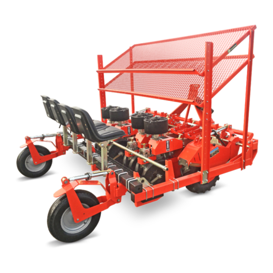
- Page 7 INFORMAZIONI TECNICHE Descrizione generale La macchina operatrice è stata progettata e costruita per Gli organi mobili (distributore, espulsore, ecc.) sono azio- la messa a dimora di piantine (ad esempio piantine orti- nati dalle ruote motrici della macchina operatrice (quan- cole, floricole, di tabacco, allevate in vivaio, ecc.), radicate do sono a contatto con il terreno) e dalla marcia della in zolla di torba a forma conica o piramidale anche di pic- trattrice.
- Page 8 BABY COMPACT/4 2500 2400 BABY COMPACT/5 2400 3000 BABY COMPACT/6 UN41-0047CF Caratteristiche tecniche BABY COMPACT/3 BABY COMPACT/4 BABY COMPACT/5 BABY COMPACT/6 Potenza trattrice richiesta Distanza minima interfila Standard minima 14 - massima 50 Distanza Opzionale minima 31 - massima 82 interpianta...
- Page 9 Dichiara sotto la propria responsabilità che le macchine Budrio trapiantatrici in oggetto: BABY COMPACT/3, BABY COMPACT/4, CHECCHI & MAGLI s.r.l BABY COMPACT/5, BABY COMPACT/6 Legale rappresentante sono conformi ai Requisiti Essenziali di Sicurezza e di Tu- Nerio Checchi tela della Salute di cui alla Direttiva 2006/42/CE.
- Page 10 INFORMAZIONI TECNICHE Segnali di sicurezza e informazione L’illustrazione raffigura la posizione e il significato delle ATTENZIONE targhe applicate. Verificare che le targhe siano leggibili; in caso contra- rio pulirle e se danneggiate sostituirle applicandole nella posizione originale. RAPID SHIFT FOXDRIVE (5 P) RAPID SHIFT DX 402783 BUDRIO (BO)
- Page 11 Ripiano supplementare porta-vassoi trasversale cm 350 Ripiano supplementare porta-vassoi trasversale cm 400 Dispositivo di posa manichetta d’irrigazione Kit ruota flex frontale BABY COMPACT (non compatibile con slitta skid) Kit vomere stretto BABY COMPACT Kit vomere standard BABY COMPACT Kit vomere medio BABY COMPACT...
- Page 12 INFORMAZIONI SULLA SICUREZZA Leggere attentamente questo manuale prima di pro- Durante l’uso utilizzare gli indumenti e/o i dispositivi cedere alle operazioni di impiego, manutenzione o di protezione individuali previsti dalle leggi vigenti altri interventi sulla macchina operatrice. in materia di sicurezza sul lavoro. Prestare attenzione e rispettare le simbologie appli- Meglio perdere il tempo necessario per il rientro al cate sulla macchina operatrice in modo particolare...
- Page 13 Per contenere gli ingombri dell’imballo la macchina è smontata in uno o più colli. UN41-0004AF Dimensioni indicative dell’imballo BABY COMPACT/3 BABY COMPACT/4 BABY COMPACT/5 BABY COMPACT/6 Colli (n°) A (cm) B (cm) C (cm) Movimentazione e sollevamento dell’imballo...
- Page 14 INFORMAZIONI SULLA MOVIMENTAZIONE E INSTALLAZIONE Disimballo e montaggio In fase di disimballo controllare l’integrità e l’esatta quan- ATTENZIONE tità dei componenti; in caso di danni, segnalare al riven- ditore o direttamente al costruttore i danni subiti entro 8 Il montaggio della macchina operatrice deve essere giorni dal ricevimento della macchina.
- Page 15 ATTENZIONE macchine operatrici specificati nel manuale. Nella fase di sollevamento prestare attenzione alle Nei modelli BABY COMPACT/3 e BABY COMPACT/5 oscillazioni del carico perché il punto di presa non è deve essere smontato il sedile per permettere il montag- mai perfettamente baricentrico.
- Page 16 INFORMAZIONI SULLE REGOLAZIONI Raccomandazioni di sicurezza per le regolazioni Gli interventi di regolazione devono essere effettuati accensione rimossa e adottare tutti gli accorgimenti su terreno pianeggiante, compatto, con la trattrice necessari per operare in sicurezza. spenta, il freno di stazionamento tirato, la chiave di Regolazione distanza delle ruote costipatrici dal vomere Le ruote costipatrici (C) servono a rincalzare e compri- mere il terreno attorno alle piantine trapiantate.
- Page 17 INFORMAZIONI SULLE REGOLAZIONI Regolazione profondità di trapianto Per questa operazione procedere come descritto. 1) Ruotare il pomello (A) per aumentare o diminuire la profondità del solco. UN41-0659BO Regolazione simmetrica delle ruote costipatrici con il vomere UN41-0660BO Le ruote costipatrici possono sfregare contro il vomere a 2) Centrare le ruote costipatrici con il vomere.
- Page 18 INFORMAZIONI SULLE REGOLAZIONI Regolazione dell’efficacia di costipazione Regolare adeguatamente la distanza tra le ruote costipa- trici (B) in funzione dell’esigenza. Maggiore è la distanza tra le ruote, minore è l’efficacia di costipazione. Minore è la distanza tra le ruote, maggiore è l’efficacia di costipazione.
- Page 19 INFORMAZIONI SULLE REGOLAZIONI Regolazione centratura del piatto flessibile UN41-0664BO Per questa operazione procedere come descritto. INFORMAZIONE 1) Allentare le viti (A). Verificare che il piatto flessibile non sfreghi sul vo- 2) Centrare il piatto flessibile (B) con il vomere (C). mere.
- Page 20 INFORMAZIONI SULLE REGOLAZIONI Regolazione interfila Regolare la distanza delle unità di trapianto per ottene- ATTENZIONE re la distanza tra le file (distanze comprese nelle gamme Bloccare la macchina operatrice, sollevata da terra, previste, vedere, relativamente al modello, “Caratteristi- con mezzi esterni (cavalletti, ecc.). che tecniche”).
- Page 21 INFORMAZIONI SULLE REGOLAZIONI Regolazione interpianta La distanza tra una pianta e quella successiva è deter- minata dal numero di denti dei pignoni installati e dalla quantità di bicchieri del distributore. Possono essere montate diverse serie di pignoni al fine di ottenere la distanza di interpianta richiesta. Scegliere il corretto rapporto di trasmissione se le mac- chine operatrici sono equipaggiate con cambio “Rapid Shift”.
- Page 22 INFORMAZIONI SULLE REGOLAZIONI ALLESTIMENTO OPZIONALE 31 - 82 ALLESTIMENTO OPZIONALE 31 - 82 Distanza interpianta N° denti pignoni Distanza interpianta N° denti pignoni inches inches 12 - 3/8 12 - 3/8 13 - 3/8 13 - 3/8 14 - 1/4 14 - 1/4 15 - 3/4 15 - 3/4...
- Page 23 INFORMAZIONI SULLE REGOLAZIONI ALLESTIMENTO 14 - 50 RAPID SHIFT DX Distanza interpianta N° denti pignoni inches 5 - 1/2 6 - 3/4 7 - 7/8 9 - 1/16 10 - 1/4 12 - 3/8 13 -3/8 14 - 5/8 15 - 3/4 17 - 3/4 19 - 3/4 UN41-0690BO...
- Page 24 INFORMAZIONI SULLE REGOLAZIONI Regolazione della fase distributore-espulsore Quando la pianta cade nel vomere (C), l’espulsore (B) In base alle diverse velocità di trapianto, regolare la cor- deve essere in posizione arretrata per poi iniziare la spin- retta fase tra distributore ed espulsore. ta di espulsione.
- Page 25 INFORMAZIONI SULLE REGOLAZIONI Regolazione carico del ruotino Per questa operazione procedere come descritto. 1) Ruotare il pomello (B) in senso orario o antiorario per aumentare o diminuire il carico del ruotino (A) sul terreno. UN41-0671BO Regolazione raschietto ruotino Per questa operazione procedere come descritto. 1) Allentare le viti (A).
- Page 26 INFORMAZIONI SULLE REGOLAZIONI Regolazione inclinazione della slitta Per questa operazione procedere come descritto. 1) Allentare i dadi (A) e (C). 2) Svitare e avvitare alternativamente le viti (B) e (D) per inclinare la slitta del valore indicato nell’illustrazione. 3) Avvitare i dadi (A) e (C). UN41-0674BO Regolazione trasversale della slitta UN41-0675BO...
- Page 27 INFORMAZIONI SULLE REGOLAZIONI Regolazione del carico dell’unità di trapianto Il gruppo di regolazione (A) può essere montato sia in posizione (A1) che in posizione (A2). Il gruppo di regolazione viene solitamente montato in posizione (A1). Il gruppo in posizione (A1) consente di diminuire il peso alle ruote costipatrici.
- Page 28 INFORMAZIONI SULLE REGOLAZIONI Regolazione ripiani magazzino vassoi I ripiani possono essere spostati in altezza, distanziati o PRUDENZA avvicinati tra di loro e con differenti pendenze. Regolare i ripiani in rapporto alla dimensione delle pian- Prima di svitare i dadi e i bulloni, sostenere adegua- tine e in posizione tale da fare assumere all’operatore la tamente i ripiani per evitare movimenti imprevisti posizione di massimo comfort ogni volta che preleva le...
- Page 29 INFORMAZIONI SULLE REGOLAZIONI Regolazione guide porta-vassoi (opzionale) Regolare la distanza delle guide in rapporto alla dimen- Il gioco tra le guide ed il vassoio deve essere tale da met- sione dei vassoi. tere e togliere il vassoio senza sfilarlo lungo le guide. UN41-0694DO Per questa operazione procedere come descritto.
- Page 30 INFORMAZIONI SULLE REGOLAZIONI Regolazione del gioco tra guide e vassoi (opzionale) UN41-0695DO Per questa operazione procedere come descritto. Il gioco tra le guide (B) e (F) ed il vassoio (L) deve es- sere tale da mettere e togliere il vassoio senza sfilarlo 1) Allentare i bulloni (A) ed (E) delle guide.
- Page 31 INFORMAZIONI SULL’USO Raccomandazioni per la sicurezza per l’uso Consentire l’uso della macchina solo a personale au- Non superare le pendenze massime ammissibili della torizzato, in buona salute, adeguatamente formato e trattrice con attrezzatura applicata (vedere manuale dotato di idonea patente di guida per la trattrice. d’uso della trattrice).
- Page 32 INFORMAZIONI SULL’USO Attacco e distacco della macchina operatrice dalla trattrice ATTENZIONE ATTENZIONE Il collegamento della macchina operatrice alla trattri- Collegare la macchina operatrice solo ad una trat- ce è uno dei momenti più rischiosi poiché potrebbe ri- trice di adeguata potenza e provvista di sollevatore chiedere la necessità...
- Page 33 INFORMAZIONI SULL’USO Cambio rapporto trasmissione (Rapid Shift) INFORMAZIONE ATTENZIONE Il cambio del rapporto della trasmissione ha lo scopo Spegnere il motore della trattrice, disinserire e custo- di ottenere l’interpianta richiesto. dire la chiave di accensione per prevenire il pericolo Fare riferimento al capitolo “Regolazione interpian- di infortunio durante la fase del cambio del rapporto ta”...
- Page 34 INFORMAZIONI SULL’USO Modalità di trapianto della piantina dal distributore e per favorirne l’attecchi- La messa a dimora delle piantine deve essere effettuata su terreni preventivamente sminuzzati con erpici o zap- mento. patrici e leggermente compattati in superficie. Non operare su terreni molto soffici, molto compatti o Non caricare nel distributore piantine con zolla incom- molto bagnati per non pregiudicare la buona qualità...
- Page 35 INFORMAZIONI SULL’USO Operazioni in fase di trapianto chieri apribili, non caricare le piantine nei bicchieri anteriori poiché sono continuamente in fase di aper- 1) Per evitare sovraccarichi al vomere, l’operatore a bor- tura / chiusura. do della trattrice deve abbassare la macchina opera- 6) Gli operatori a bordo della macchina operatrice de- trice con la trattrice in lento avanzamento.
- Page 36 INFORMAZIONI SULL’USO Circolazione su strade pubbliche Nel trasferimento del complesso macchina operatrice- ATTENZIONE trattrice osservare le prescrizioni del codice della strada. È obbligatorio bloccare l’attacco a tre punti con gli appo- È vietato trasportare persone e/o cose sulla macchi- siti puntoni (A) per impedire qualsiasi oscillazione della na operatrice.
- Page 37 INFORMAZIONI SULLA MANUTENZIONE Raccomandazioni di sicurezza per la manutenzione Gli interventi di manutenzione devono essere ef- manutenzione ordinaria previsti nel manuale istru- fettuati su terreno pianeggiante, compatto, con la zioni. trattrice spenta, il freno di stazionamento tirato, la Per gli interventi straordinari (non compresi in que- chiave di accensione rimossa e adottando tutti gli ac- sto manuale) occorre disporre di un’officina azienda- corgimenti necessari per operare in sicurezza.
- Page 38 INFORMAZIONI SULLA MANUTENZIONE Pulizia del vomere aprisolco La mancata pulizia limita l’escursione dell’espulsore Pulire il vomere dai detriti, fango, torba, residui vegetali ecc. che si sono accumulati durante l’uso. per cui oltre a pregiudicare il buon funzionamento causa gravi danni meccanici. UN41-0681BO Per questa operazione procedere come descritto.
- Page 39 INFORMAZIONI SULLA MANUTENZIONE Schema punti di lubrificazione Lubrificare gli organi raffigurati nei tempi e nei modi in- di inquinare il lubrificante distribuito. dicati. Usare grasso universale per autotrazione di macchinari Prima di effettuare la lubrificazione pulire accuratamen- agricoli e industriali, idrorepellente con punto di goccia te i componenti interessati e gli ingrassatori per evitare 180°.
- Page 40 INFORMAZIONI SULLA MANUTENZIONE Inconvenienti, cause, rimedi L’elenco riporta alcuni inconvenienti e i relativi rimedi che possono capitare durante la fase di lavoro. Inconveniente Probabile causa Rimedio La profondità di trapianto non è Eseguire la regolazione (vedere corretta “Regolazione profondità di trapianto”) La piantina a dimora è...
- Page 41 INFORMAZIONI SULLE SOSTITUZIONI Raccomandazioni di sicurezza per le sostituzioni La sostituzione di componenti usurati o danneggiati le avente le caratteristiche indicate dalla legislazione deve essere effettuata con ricambi originali. vigente in materia (attrezzature adeguate, personale Per gli interventi straordinari (non compresi in que- idoneo, ecc.), altrimenti occorre rivolgersi ad officine sto manuale) occorre disporre di un’officina azienda- autorizzate.
- Page 42 INFORMAZIONI SULLE SOSTITUZIONI Sostituzione catena ruote motrici UN41-0510MM Montare una nuova catena. Per questa operazione procedere come descritto. Montare il carter (D). Azionare la leva (E) per sollevare la ruota con lo sco- Avvitare i pomelli (C). po di ridurre la tensione della catena. 10) Montare il carter (B).
- Page 43 INFORMAZIONI SULLE SOSTITUZIONI Per questa operazione procedere come descritto. PRUDENZA 1) Azionare la leva (C) per sollevare la ruota con lo sco- po di ridurre la tensione della catena. Il tenditore potrebbe compiere un movimento re- 2) Svitare i dadi (A). pentino e provocare lesioni alle mani.
- Page 44 INFORMAZIONI SULLE SOSTITUZIONI Sostituzione del raschietto ruote costipatrici Per questa operazione procedere come descritto. 1) Rimuovere la spina di sicurezza (A). 2) Rimuovere l’anello elastico (B). 3) Togliere la rondella (C). 4) Svitare la vite (D). 5) Sfilare dall’albero il raschietto. 6) Montare il nuovo raschietto.
- Page 45 INFORMAZIONI SULLE SOSTITUZIONI Sostituzione vomere UN41-0687BO 6) Spingere in avanti il vomere e ruotarlo verso il basso. Per questa operazione procedere come descritto. 7) Sorreggere il vomere e rimuovere la vite (G) e la ron- 1) Azionare la leva (A) e ruotare verso il basso la guida della (H).
- Page 46 INFORMAZIONI SULLE SOSTITUZIONI Sostituzione pattino UN41-0688BO Fase di montaggio ATTENZIONE 1) Inserire il nuovo pattino all’interno della guida (A). Nella fase di smontaggio, prestare attenzione alla 2) Infilare le viti (B). elasticità del pattino che, sbloccato dalla guida, as- 3) Avvitare i dadi (C). sume repentinamente la posizione iniziale (diritta) e 4) Fare aderire il pattino alla guida e bloccarlo in posi- potrebbe causare infortunio.
- Page 47 SUMMARY 1 GENERAL INFORMATION ..........................1 2 TECHNICAL INFORMATION ........................3 3 SAFETY INFORMATION ..........................8 4 INFORMATION CONCERNING HANDLING AND INSTALLATION ..........9 5 ADJUSTMENT INFORMATION ......................12 6 INFORMATION FOR USE ........................27 7 MAINTENANCE INFORMATION ......................33 8 INFORMATION CONCERNING REPLACEMENTS ................37 ANALYTICAL INDEX Adjusting the automatic safety release function ................
- Page 48 Handling and lifting the packed unit ......................9 Hitching and unhitching the work vehicle to and from the tractor ..........28 Information and safety signs .........................6 Lifting and transporting the work vehicle .................... 11 Loading, transporting and unloading the work vehicle/tractor assembly ....... 11 Lubrication diagram ............................
- Page 49 GENERAL INFORMATION Aim of the manual This instruction manual is produced by the manufacturer To highlight certain parts of the manual’s contents to provide all those who have dealings with the planting deemed important for safety or information reasons the machine (which may also be referred to hereinafter as following symbols have been used, whose meanings are the ‘work vehicle’) with all the necessary information and...
- Page 50 GENERAL INFORMATION Assistance request procedure Whenever making requests for technical assistance con- All requests for technical assistance must be made to the cerning the work vehicle, remember to quote the data manufacturer's Technical Assistance Service or the au- shown on the data plate and the fault encountered. thorised service centres.
- Page 51 TECHNICAL INFORMATION General description This work vehicle is designed and built for planting seed- The moving parts (dispenser, ejector, etc.) are driven lings of various kinds (e.g. horticultural, floral, tobacco, by the works vehicle’s driving wheels (when these are nursery-grown, etc.), rooted in conical or pyramid- touching the ground) and the movement of the tractor.
- Page 52 2500 2400 BABY COMPACT/5 2400 3000 BABY COMPACT/6 UN41-0047CF Technical characteristics BABY COMPACT/3 BABY COMPACT/4 BABY COMPACT/5 BABY COMPACT/6 Required tractor power Minimum row spacing Standard minimum 14 - maximum 50 Plant spacing Optional minimum 31 - maximum 82 distance...
- Page 53 EN 13857, on machine safety. Hereby declares, under its own responsibility that the Budrio planting machine in question, i.e. models: BABY COMPACT/3, BABY COMPACT/4, CHECCHI & MAGLI s.r.l BABY COMPACT/5, BABY COMPACT/6 Legal representative comply with the Essential and Health Safety Require- Nerio Checchi ments provided for by Directive 2006/42/CE.
- Page 54 TECHNICAL INFORMATION Information and safety signs The illustration shows the locations and meanings of the WARNING signs affixed. Check that all the plates are legible; if they are not, clean them or - if they are damaged - replace them, applying the new ones in the same place as the old ones.
- Page 55 Manual lift row tracers (max. row spacing: cm 150) Hydraulic lift row tracers BABY COMPACT continuous flow watering device positioned between the ploughshares Optional kit for distances on the row cm 31 - 82 cm 10 - 12 plant spacing kit...
- Page 56 SAFETY INFORMATION Read this manual carefully before proceeding with During use, wear the personal protective equipment any operations concerning use, maintenance or oth- and clothing envisaged by the laws in force on safety er work on the work vehicle. in the workplace. Heed and comply with the symbols on the work vehi- It is more advisable to take the time needed to return cle, especially those concerning safety.
- Page 57 To contain packing as far as possible, the machine is de- livered dismantled and in one or more parcels. UN41-0004AF Approximate packing dimensions BABY COMPACT/3 BABY COMPACT/4 BABY COMPACT/5 BABY COMPACT/6 Parcels (n°) A (cm)
- Page 58 INFORMATION CONCERNING HANDLING AND INSTALLATION Unpacking and assembly During unpacking, check that the components are in WARNING good condition and tally with the number stated; in the event of damage, report the damage to the retailer or The assembly of the work vehicle must be carried out directly to the manufacturer within 8 days of receiving at an authorised service centre or at company facili- the machine.
- Page 59 During lifting watch out for the load swinging, as For models BABY COMPACT/3 - BABY COMPACT/5, the the hook-up point is never perfectly at the centre of seat must be removed to allow the lifting means to be gravity.
- Page 60 ADJUSTMENT INFORMATION Safety advice for the adjustments Adjustment work must be carried out with the work moved, and adopting all the necessary safety meas- vehicle on flat, compact ground, with the tractor en- ures required to work safely. gine off, parking brake engaged, and ignition key re- Adjusting the spacing between the packing wheels and the ploughshare The packing wheels (C) are used to ridge and compact the soil around the planted seedlings.
- Page 61 ADJUSTMENT INFORMATION Planting depth adjustment For this operation, proceed as outlined below. 1) Turn the knob (A) to increase or decrease the depth of the furrow. UN41-0659BO Adjusting the symmetry between the packing wheels and the ploughshare UN41-0660BO Because of their incorrect position, the packing wheels 2) Centre the packing wheels with the ploughshare.
- Page 62 ADJUSTMENT INFORMATION Adjusting the packing efficiency Adjust the spacing between the packing wheels (B) as required. The farther apart the wheels are, the less efficient the packing is. The closer the wheels are, the more efficient the packing Proceed as outlined below. Remove the pins (A).
- Page 63 ADJUSTMENT INFORMATION Adjusting the flexible plate centring UN41-0664BO For this operation, proceed as outlined below. NOTICE 1) Loosen the screws (A). Check that the flexible plate does not rub against the 2) Centre the flexible plate (B) in relation to the share ploughshare.
- Page 64 ADJUSTMENT INFORMATION Adjusting the row spacing “Technical characteristics” schedule). WARNING Keep the minimum distance stated on the illustration Secure the work vehicle in position (lifted off the between the seedlings and the tractor wheels. ground) with external means (trestles, etc.). Do not stand under the hoisted machine unless it is Adjust the seat position accordingly.
- Page 65 ADJUSTMENT INFORMATION Adjusting the plant spacing The space between one plant and the next depends on the number of teeth on the pinions installed and on the number of cups of the dispensing unit. A series of pinions may be fitted to ensure the required plant spacing is obtained.
- Page 66 ADJUSTMENT INFORMATION OPTIONAL EQUIPMENT PACKAGE 31 - 82 OPTIONAL EQUIPMENT PACKAGE 31 - 82 Plant spacing distance N. teeth on the pinions Plant spacing distance N. teeth on the pinions inches inches 12 - 3/8 12 - 3/8 13 - 3/8 13 - 3/8 14 - 1/4 14 - 1/4...
- Page 67 ADJUSTMENT INFORMATION EQUIPMENT PACKAGE 14 - 50 RAPID SHIFT (RH) Plant spacing distance N. teeth on the pinions inches z 1 z 2 z 3 z 4 z 5 z 6 5 - 1/2 6 - 3/4 7 - 7/8 9 - 1/16 10 - 1/4 17 17...
- Page 68 ADJUSTMENT INFORMATION Adjusting the dispensing / ejection timing When the plant falls into the ploughshare (C), the ejector Adjust the correct phase between the dispensing unit (B) should be in the rear position and should then start and the ejector according to the different planting pushing the plant to eject it.
- Page 69 ADJUSTMENT INFORMATION Adjusting the small wheel load For this operation, proceed as outlined below. 1) Turn the knob (B) clockwise or anticlockwise to in- crease or decrease the load of the small wheel (A) on the ground. UN41-0671BO Adjusting the the small wheel scraper For this operation, proceed as outlined below.
- Page 70 ADJUSTMENT INFORMATION Adjusting the skid inclination For this operation, proceed as outlined below. 1) Loosen nuts (A) and (C). 2) Alternately loosen and tighten the screws (B) and (D) to tilt the skid by the amount shown. 3) Tighten nuts (A) and (C). UN41-0674BO Adjusting the skid crosswise UN41-0675BO...
- Page 71 ADJUSTMENT INFORMATION Adjusting the planting unit load The adjustment unit (A) can be mounted in either posi- tion (A1) or position (A2). The adjustment unit is usually mounted in position (A1). With the unit in position (A1) the weight on the packing wheels can be reduced.
- Page 72 ADJUSTMENT INFORMATION Adjusting the tray loader shelves The shelves can be adjusted heightwise, they can be CAUTION moved either farther apart or closer together, and the tilt angle can also be altered. Before unscrewing the nuts and bolts, prop up the Adjust the shelves according to the size of seedlings, po- shelves to prevent any sudden movements causing sitioning them so that the operator is as comfortable as...
- Page 73 ADJUSTMENT INFORMATION Adjusting the tray runners (optional) Adjust the runner spacing according to the size of the There must be enough clearance between the runners trays. and the tray to allow the tray to be inserted and removed without having to slide it along the runners. UN41-0694DO For this operation, proceed as outlined below.
- Page 74 ADJUSTMENT INFORMATION Adjusting the clearance between the runners and trays (optional) UN41-0695DO For this operation, proceed as outlined below. There must be enough clearance between the run- ners (B) and (F) and the tray (L) to allow the tray to 1) Loosen the runner bolts (A) and (E).
- Page 75 INFORMATION FOR USE Safety advice concerning use This ensures the machine can only be used by fit and Do not exceed the permitted gradients established healthy personnel, who are suitably trained and au- for the tractor with the equipment mounted on it thorised, and hold the appropriate category driving (see tractor user manual).
- Page 76 INFORMATION FOR USE Hitching and unhitching the work vehicle to and from the tractor WARNING WARNING Hitching the work vehicle up to the tractor is one of The work vehicle must only ever be coupled to a the riskiest moments as it could required the involve- tractor with an appropriate power rating which is ment of several people at once, carrying out synchro- equipped with a lift that complies with the regula-...
- Page 77 INFORMATION FOR USE Changing the transmission ratio (Rapid Shift) NOTICE WARNING The aim of the change of the transmission ratio is to Switch off the tractor engine, remove the ignition obtain the required plant spacing. key, and store in a safe place to prevent an accident See the “Adjusting the plant spacing”...
- Page 78 INFORMATION FOR USE Planting procedure dispenser better and also take root. The seedlings must be planted in soil which has been finely tilled with a harrow or hoeing machine and lightly Do not work on extremely spongy spoil, or extremely compacted on the surface.
- Page 79 INFORMATION FOR USE Planting operations In the machines equipped with a dispenser with cups that open, do not load the seedlings into the front 1) To prevent overloads on the ploughshare, the tractor cups as they are continually opening and closing. driver must lower the work vehicle with the tractor 6) The operators on the work vehicle must advise the moving forwards at low speed.
- Page 80 INFORMATION FOR USE Transit on public roads When transporting the work vehicle/tractor assembly, WARNING the regulations of the highway code must always be complied with. It is prohibited to carry people and/or things on the Obligatorily, the three-point hitch must be secured with work vehicle.
- Page 81 MAINTENANCE INFORMATION Safety advice for maintenance Maintenance work must be carried out with the work maintenance envisaged in the instruction manual. vehicle on flat, compact ground, with the tractor en- Special maintenance operations (non included in gine off, parking brake engaged, and ignition key re- this handbook) require a specialised workshop on moved, and adopting all the necessary safety meas- the premises which meets the requirements speci-...
- Page 82 MAINTENANCE INFORMATION Cleaning the ploughshare Lack of cleaning will limit the ejector range, there- Clean the ploughshare to remove any debris, mud, peat, plant residues etc that may have built up during use. fore, as well as affecting the machine’s operation, it also causes serious mechanical damage.
- Page 83 MAINTENANCE INFORMATION Lubrication diagram Lubricate the parts shown at the times and in the ways the lubricant. specified. Use universal grease for traction in farming and industri- Before lubricating, clean the components concerned al machinery, which is water-repellent with a 180° drop and the greasing nipples to prevent contamination of point.
- Page 84 MAINTENANCE INFORMATION Troubleshooting The following list contains a number of common problems that may arise during work, together with the ways to solve them. Problem Likely cause Solution Make the relative adjustment (see Incorrect planting depth “Adjusting the planting depth”) The seedling planted is too close to the surface or too deep The dispenser is not synchronised...
- Page 85 INFORMATION CONCERNING REPLACEMENTS Safety advice in case of replacements When replacing worn or damaged parts, original the premises which meets the requirements speci- spares must always be used. fied by the relative laws in force (appropriate equip- Special maintenance operations (non included in ment suitably trained staff etc.);...
- Page 86 INFORMATION CONCERNING REPLACEMENTS Replacing the driving wheels chain UN41-0510MM Fit a new chain. For this operation, proceed as outlined below. Fit the casing (D). Move the lever (E) to lift the wheel in order to slack- Tighten the knobs (C). en off the chain.
- Page 87 INFORMATION CONCERNING REPLACEMENTS For this operation, proceed as outlined below. CAUTION 1) Move the lever (C) to lift the wheel in order to slacken off the chain. The tensioner could move unexpectedly, causing in- 2) Unscrew the nuts (A). jury to the hands. 3) Remove the casing (B).
- Page 88 INFORMATION CONCERNING REPLACEMENTS Replacing the packing wheels scraper For this operation, proceed as outlined below. 1) Remove the lock pin (A). 2) Remove the circlip (B). 3) Remove the washer (C). 4) Unscrew the screw (D). 5) Slide the scraper off the shaft. 6) Fit the new scraper.
- Page 89 INFORMATION CONCERNING REPLACEMENTS Replacing the ploughshare UN41-0687BO Proceed as outlined below. 6) Push the ploughshare forwards and turn it so it is fac- ing downwards. 1) Move the lever (A) and turn the guide (B) downwards, if fitted. 7) Hold the ploughshare and remove the screw (G) and washer (H).
- Page 90 INFORMATION CONCERNING REPLACEMENTS Replacing the slider UN41-0688BO Assembly WARNING 1) Fit the new slider into the guide (A). During disassembly, watch out for the elasticity of 2) Insert the screws (B). the slider since, when it is released from the rail, it 3) Tighten the nuts (C).
-
Page 91: Table Of Contents
SOMMAIRE 1 INFORMATIONS GENERALES........................1 2 INFORMATIONS TECHNIQUES ........................3 3 INFORMATIONS CONCERNANT LA SECURITE ...................8 4 INFORMATIONS CONCERNANT LA MANUTENTION ET L’INSTALLATION ........9 5 INFORMATIONS CONCERNANT LES REGLAGES ................12 6 INFORMATIONS CONCERNANT L’UTILISATION................27 7 INFORMATIONS CONCERNANT L’ENTRETIEN ................. 33 8 INFORMATIONS CONCERNANT L’ENTRETIEN ................. - Page 92 Pentes admises ..............................5 Période d’inactivité prolongée de la machine opératrice ............... 32 Principaux éléments ............................3 Problèmes, causes, solutions........................36 Protections ................................5 Recommandations concernant la sécurité durant l’utilisation ............27 Recommandations de sécurité pour l’entretien .................. 33 Recommandations de sécurité pour les réglages ................12 Recommandations de sécurité...
-
Page 93: Informations Generales
INFORMATIONS GENERALES Objectif du manuel Le manuel a été réalisé par le constructeur pour fournir portantes pour la sécurité ou pour indiquer des infor- les informations nécessaires et les critères à suivre à tous mations importantes, on a adopté des symboles dont la ceux qui interagisssent avec la repiqueuse, également signification est décrite ci-après. - Page 94 INFORMATIONS GENERALES Modalités à suivre pour les demandes d’assistance Pour toute demande d’assistance technique concernant Les demandes d’assistance technique devront être adres- la machine opératrice, indiquer les données figurant sur sées au Service d’Assistance Technique du constructeur la plaque d’identification et le défaut relevé. ou aux centres d’assistance autorisés.
-
Page 95: Informations Techniques
INFORMATIONS TECHNIQUES Description générale La machine opératrice a été conçue et construite pour la Les organes mobiles (distributeur, éjecteur, etc.) sont ac- mise en terre de plants (par exemple des plants de légu- tionnés par les roues motrices de la machine opératrice mes, de fleurs, de tabac, élevés dans une pépinière, etc.), (lorsqu’elles sont au contact du sol) et par la marche du enracinés en motte de tourbe conique ou pyramidale... - Page 96 2500 2400 BABY COMPACT/5 2400 3000 BABY COMPACT/6 UN41-0047CF Caractéristiques techniques BABY COMPACT/3 BABY COMPACT/4 BABY COMPACT/5 BABY COMPACT/6 Puissance requise pour le tracteur Distance minimale entre les rangées Standard minimale 14 - maximale 50 Distance entre les Option minimale 31 - maximale 82...
- Page 97 40054 – BUDRIO (BOLOGNA) - ITALIA la sécurité des machines. Déclare, sous sa propre responsabilité, que les machines Budrio repiqueuses en question: BABY COMPACT/3, BABY COMPACT/4, CHECCHI & MAGLI s.r.l BABY COMPACT/5, BABY COMPACT/6 Représentant Légal sont conformes aux Exigences Essentielles de Sécurité et Nerio Checchi de Tutelle de la Santé...
- Page 98 INFORMATIONS TECHNIQUES Signaux de sécurité et d’information L’illustration représente la position et la signification des ATTENTION plaques appliquées. Vérifier que les plaques sont lisibles; dans le cas contraire, les nettoyer et, si elles sont endommagées, les remplacer en les appliquant dans leur position d'origine.
- Page 99 Niveau supplémentaire porte-plateaux transversal cm 350 Niveau supplémentaire porte-plateaux transversal cm 400 Dispositif de pose de la manchette d’irrigation Kit roue flex frontale BABY COMPACT (non compatible avec le patin skid) Kit soc étroit BABY COMPACT Kit soc standard BABY COMPACT...
-
Page 100: Informations Concernant La Securite
INFORMATIONS CONCERNANT LA SECURITE Lire attentivement ce manuel avant de procéder aux Durant l’utilisation, utiliser les vêtements et/ou les opérations d’utilisation, d’entretien ou à d’autres in- dispositifs individuels de protection prévus par les terventions sur la machine opératrice. lois en vigueur en matière de sécurité sur le lieu de travail. - Page 101 Pour limiter l'encombrement de l’emballage, la machine est démontée en un ou plusieurs colis. UN41-0004AF Dimensions indicatives de l’emballage BABY COMPACT/3 BABY COMPACT/4 BABY COMPACT/5 BABY COMPACT/6 Colis (n°) A (cm)
- Page 102 INFORMATIONS CONCERNANT LA MANUTENTION ET L’INSTALLATION Déballage et montage Au déballage, contrôler l’état et la quantité exacte des ATTENTION composants; en cas de dégâts, signaler au revendeur ou directement au constructeur les dommages subis dans Le montage de la machine opératrice doit être réalisé un délai de 8 jours à...
- Page 103 Durant la phase de levage, faire attention aux oscilla- Sur les modèles BABY COMPACT/3 et BABY COMPACT/5, tions de la charge car le point de prise n’est jamais démonter le siège pour permettre le montage de l’outil parfaitement barycentrique.
-
Page 104: Informations Concernant Les Reglages
INFORMATIONS CONCERNANT LES REGLAGES Recommandations de sécurité pour les réglages Les interventions de réglage doivent être effectuées de contact retirée du tableau de bord; prendre tou- sur un terrain plat et compact; le moteur du tracteur tes les mesures nécessaires pour opérer en toute sé- doit être coupé, le frein de stationnement tiré, la clé... - Page 105 INFORMATIONS CONCERNANT LES REGLAGES Réglage de la profondeur de repiquage Pour cette opération, suivre la description. 1) Tourner la poignée (A) pour augmenter ou réduire la profondeur du sillon. UN41-0659BO Réglage symétrique des roues de compactage par rapport au soc UN41-0660BO Les roues de compactage peuvent frotter contre le soc si 2) Centrer les roues de compactage sur le soc.
- Page 106 INFORMATIONS CONCERNANT LES REGLAGES Réglage de l’efficacité du tassement Régler minutieusement la distance entre les roues tas- seuses (B) suivant les exigences. Plus la distance entre les roues est grande, moins le tas- sement est efficace. Moins la distance entre les roues est grande, plus le tas- sement est efficace.
- Page 107 INFORMATIONS CONCERNANT LES REGLAGES Réglage du centrage du disque flexible UN41-0664BO Pour cette opération, suivre la description. INFORMATION 1) Desserrer les vis (A). Vérifier que le disque flexible ne frotte pas sur le soc. 2) Centrer le disque flexible (B) par rapport au soc (C). 3) Serrer les vis (A).
- Page 108 INFORMATIONS CONCERNANT LES REGLAGES Réglage de la distance entre les rangées gammes prévues, voir, en fonction du modèle, “Caracté- ATTENTION ristiques techniques”). Bloquer la machine soulevée au-dessus du sol, avec Maintenir une distance minimale entre le plant et les des moyens externes (trépieds, etc.). roues du tracteur d’après la figure.
- Page 109 INFORMATIONS CONCERNANT LES REGLAGES Réglage de la distance entre les plants La distance entre deux plants est déterminée par le nombre de dents des pignons installés et de la quantité de godets du distributeur. On peut monter différentes séries de pignons pour obte- nir la distance nécessaire entre les plants.
- Page 110 INFORMATIONS CONCERNANT LES REGLAGES EQUIPEMENT EN OPTION 31 - 82 EQUIPEMENT EN OPTION 31 - 82 Distance entre les plants N° dents des pignons Distance entre les plants N° dents des pignons inches inches 12 - 3/8 12 - 3/8 13 - 3/8 13 - 3/8 14 - 1/4...
- Page 111 INFORMATIONS CONCERNANT LES REGLAGES EQUIPEMENT 14 - 50 RAPID SHIFT (D) Distance entre les plants N° dents des pignons inches z 1 z 2 z 3 z 4 z 5 z 6 5 - 1/2 6 - 3/4 7 - 7/8 9 - 1/16 10 - 1/4 17 17...
- Page 112 INFORMATIONS CONCERNANT LES REGLAGES Réglage de la phase distributeur-éjecteur Quand le plant tombe dans le soc (C), l’éjecteur (B) doit Régler la phase entre le distributeur et l'éjecteur en fonc- se trouver en arrière pour commencer la poussée d’éjec- tion des différentes vitesses de repiquage. tion.
- Page 113 INFORMATIONS CONCERNANT LES REGLAGES Réglage de la charge du rouet Pour cette opération, suivre la description. 1) Tourner la poignée (B) en sens horaire ou inverse ho- raire pour augmenter ou réduire la charge du rouet (A) sur le terrain. UN41-0671BO Réglage du racloir du rouet Pour cette opération, suivre la description.
- Page 114 INFORMATIONS CONCERNANT LES REGLAGES Réglage de l'inclinaison du patin Pour cette opération, suivre la description. 1) Desserrer les écrous (A) et (C). 2) Dévisser et revisser tour à tour les vis (B) et (D) pour incliner le patin de la valeur indiquée sur la figure. 3) Visser les écrous (A) et (C).
- Page 115 INFORMATIONS CONCERNANT LES REGLAGES Réglage de la charge de l’unité de repiquage Le groupe de réglage (A) peut être monté dans la posi- tion (A1) ou dans la position (A2). Le groupe de réglage est généralement monté dans la position (A1). Le groupe dans la position (A1) permet de réduire le poids au niveau des roues de compactage.
- Page 116 INFORMATIONS CONCERNANT LES REGLAGES Réglage des étagères du magasin à plateaux Les étagères peuvent être déplacées en hauteur, espa- PRUDENCE cées ou rapprochées et on peut régler leur inclinaison. Régler les niveaux par rapport à la dimension des plants Avant de dévisser les écrous et les boulons, soute- et dans une position assurant à...
- Page 117 INFORMATIONS CONCERNANT LES REGLAGES Réglage des glissières à plateaux (option) Régler la distance des glissières en fonction de la dimen- Le jeu entre les glissières et le plateau doit permettre de sion des plateaux. placer et d'enlever le plateau sans le faire coulisser sur les glissières.
- Page 118 INFORMATIONS CONCERNANT LES REGLAGES Réglage du jeu entre les glissières et les plateaux (option) UN41-0695DO Pour cette opération, suivre la description. Le jeu entre les glissières (B) et (F) et le plateau (L) doit permettre de placer et d’enlever le plateau sans 1) Desserrer les boulons (A) et (E) des glissières.
-
Page 119: Informations Concernant L'utilisation
INFORMATIONS CONCERNANT L’UTILISATION Recommandations concernant la sécurité durant l’utilisation Ne confier l’utilisation de la machine qu’à du person- Ne pas dépasser les pentes maximales admises pour nel autorisé, en bonne santé, dûment formé et muni le tracteur lorsque l’équipement est appliqué (voir du permis de conduire pour les tracteurs. -
Page 120: Attelage Et Dételage De La Machine Opératrice Du Tracteur
INFORMATIONS CONCERNANT L’UTILISATION Attelage et dételage de la machine opératrice du tracteur ATTENTION ATTENTION Le raccordement de la machine opératrice au tracteur N’atteler la machine opératrice qu’à une tracteur est l’un des moments les plus dangereux car il pour- d’une puissance adéquate et équipé d’un dispositif rait exiger l’intervention simultanée de plusieurs per- de levage conforme aux normes en vigueur respec- sonnes accomplisant des manœuvres synchronisées... -
Page 121: Changement De Rapport De Transmission (Rapid Shift)
INFORMATIONS CONCERNANT L’UTILISATION Changement de rapport de transmission (Rapid Shift) INFORMATION ATTENTION Le changement de rapport de transmission a pour Couper le moteur du tracteur, extraire et conserver la but la réalisation du repiquage souhaité. clé de contact pour prévenir tout danger d'accident Voir le chapitre “Réglage distance entre les plants”... - Page 122 INFORMATIONS CONCERNANT L’UTILISATION Modalités de repiquage distributeur et pour en favoriser l’enracinement. Repiquer les plants dans un terrain préalablement émietté à la herse ou avec une sarcleuse et légèrement Ne pas opérer sur des terrains trop meubles, trop com- tassé en surface. pacts ou détrempés pour ne pas compromettre la bonne qualité...
- Page 123 INFORMATIONS CONCERNANT L’UTILISATION Opérations à effectuer en phase de repiquage Sur les machines équipées du distributeur à godets ouvrants, ne pas charger les plans dans les godets an- 1) Pour éviter les surcharges sur le soc, l’opérateur à térieurs car ils sont constamment en phase d'ouver- bord du tracteur doit abaisser la machine opératrice ture / fermeture.
-
Page 124: Circulation Sur La Voie Publique
INFORMATIONS CONCERNANT L’UTILISATION Circulation sur la voie publique Durant le transfert du groupe machine opératrice-trac- ATTENTION teur, observer les prescriptions du code de la route. Il est obligatoire de boquer l’attelage à trois points avec Il est interdit de transporter des personnes et/ou des les contre-fiches (A) pour empêcher toute oscillation de choses sur la machine opératrice. - Page 125 INFORMATIONS CONCERNANT L’ENTRETIEN Recommandations de sécurité pour l’entretien Les interventions d’entretien doivent être effectuées tretien ordinaire prévues dans le manuel d’instruc- sur un terrain plat et compact; le moteur du tracteur tions. doit être coupé, le frein de stationnement tiré, la clé Pour les interventions extraordinaires (ne figurant de contact retirée du tableau de bord;...
-
Page 126: Contrôle Des Pneus
INFORMATIONS CONCERNANT L’ENTRETIEN Nettoyage du soc ouvre-sillons Un manque de nettoyage limite la course de l’éjec- Nettoyer le soc en enlevant les détritus, la boue, la tour- be, les résidus végétaux, etc. qui se sont accumulés du- teur ce qui non seulement compromet le bon fonc- rant l’utilisation. - Page 127 INFORMATIONS CONCERNANT L’ENTRETIEN Schéma des points de lubrification Lubrifier les organes illustrés en respectant les délais et de polluer le lubrifiant distribué. les modalités indiqués. Utiliser une graisse universelle pour moteurs de machi- Avant d’effectuer le graissage, nettoyer minutieusement nes agricoles et industrielles, hydrofuge avec un point les composants concernés et les graisseurs pour éviter de goutte à...
- Page 128 INFORMATIONS CONCERNANT L’ENTRETIEN Problèmes, causes, solutions La liste indique quelques problèmes et les solutions correspondantes pouvant se présenter durant la phase de tra- vail. Problème Cause probable Solution La profondeur de repiquage est Procéder au réglage (voir “Réglage de la incorrecte profondeur de repiquage”) Le plant repiqué...
- Page 129 INFORMATIONS CONCERNANT LES REMPLACEMENTS Recommandations de sécurité pour les remplacements Le remplacement des composants usés ou endom- ploitation ayant les caractéristiques indiquées par magés doit être effectué avec des pièces de rechange la législation en vigueur en la matière (équipement originales.
- Page 130 INFORMATIONS CONCERNANT LES REMPLACEMENTS Remplacement de la chaîne des roues motrices UN41-0510MM Monter une nouvelle chaîne. Pour cette opération, suivre la description. Monter le carter (D). Actionner le levier (E) pour soulever la roue afin de Serrer les boutons (C). réduire la tension de la chaîne.
- Page 131 INFORMATIONS CONCERNANT LES REMPLACEMENTS Pour cette opération, suivre la description. PRUDENCE 1) Actionner le levier (C) pour soulever la roue afin de Le tendeur pourrait effectuer un mouvement impré- réduire la tension de la chaîne. vu et blesser les mains. 2) Dévisser les écrous (A).
- Page 132 INFORMATIONS CONCERNANT LES REMPLACEMENTS Remplacement du racleur des roues tasseuses Pour cette opération, suivre la description. 1) Enlever la goupille de sécurité (A). 2) Enlever l’anneau élastique (B). 3) Enlever la rondelle (C). 4) Dévisser la vis (D). 5) Extraire le racleur de l’arbre. 6) Monter le nouveau racleur.
- Page 133 INFORMATIONS CONCERNANT LES REMPLACEMENTS Remplacement du soc UN41-0687BO 6) Pousser le soc vers l’avant et le tourner vers le bas. Pour cette opération, suivre la description. 7) Soutenir le soc et démonter la vis (G) et la rondelle 1) Actionner le levier (A) et tourner la glissière (B) vers le (H).
- Page 134 INFORMATIONS CONCERNANT LES REMPLACEMENTS Remplacement de la plaquette UN41-0688BO Phase de montage ATTENTION 1) Introduire la nouvelle plaquette à l'intérieur de la Au cours de la phase de démontage, faire très atten- glissière (A). tion à l'élasticité de la plaquette qui, débloqué de la 2) Enfiler les vis (B).
- Page 135 INHALTSANGABE 1 ALLGEMEINE INFORMATIONEN ......................1 2 TECHNISCHE INFORMATIONEN ......................3 3 INFORMATIONEN ZUR SICHERHEIT ......................8 4 INFORMATIONEN ZUR BEWEGUNG UND ZUR INSTALLATION ............9 5 INFORMATIONEN ZU DEN EINSTELLUNGEN .................. 12 6 INFORMATIONEN ZUR BENUTZUNG ....................27 7 INFORMATIONEN ZUR WARTUNG...................... 33 8 INFORMATIONEN ZU DEN AUSWECHSLUNGEN ................
- Page 136 Fahrt auf öffentlichen Straßen ........................32 Funktionsstörungen, Ursachen und Behebung .................. 36 Geräusch ................................7 Glossar ...................................2 Haftungsausschluss ............................2 Hauptelemente ..............................3 Heben und Transport der Arbeitsmaschine ..................11 Inhaltsangabe ..............................III Konformitätserklärung ............................5 Kontrolle der Reifen ............................34 Laden, Transport und Abladen der Arbeitsmaschine - Schlepper..........11 Längere Nichtbenutzung der Arbeitsmaschine ..................
- Page 137 ALLGEMEINE INFORMATIONEN Zweck des Handbuches Das vorliegenden Handbuch wurde vom Hersteller cherheit relevant sind oder die wichtige Informationen verfasst, um die erforderlichen Informationen und die enthalten, wurden einige Symbole angewendet, deren anzuwendenden Kriterien zu liefern, die alle befolgen Bedeutung im Folgenden beschrieben wird. müssen, die mit der Umpflanzmaschine umgehen, die im weiteren Verlauf des Handbuches auch als Arbeits- GEFAHR...
- Page 138 ALLGEMEINE INFORMATIONEN Anforderung von Kundendiensteingriffen Bei allen Kundendienstanforderungen für die Arbeits- Die Anforderungen von Kundendiensteingriffen müssen maschine müssen die auf dem Typenschild angegebe- an den technischen Kundendienst des Herstellers oder nen Daten sowie die aufgetretene Funktionsstörung an- an Vertragswerkstätten gerichtet werden. gegeben werden.
- Page 139 TECHNISCHE INFORMATIONEN Allgemeine Beschreibung Die Arbeitsmaschine wurde für das Umpflanzen von Die beweglichen Organe (Verteiler, Auswerfer usw.) wer- Pflanzen (zum Beispiel kleinen Gemüsepflanzen, Blu- den von den Antriebsrädern der Arbeitsmaschine ange- men, Tabakpflanzen, in Gewächshäusern vorgezogenen trieben (wenn sie im Kontakt mit dem Boden sind) sowie Pflanzen usw.) entwickelt und konstruiert, die in Torf mit von der Fahrt des Schleppers.
- Page 140 BABY COMPACT/4 2500 2400 BABY COMPACT/5 2400 3000 BABY COMPACT/6 UN41-0047CF Technische Daten BABY COMPACT/3 BABY COMPACT/4 BABY COMPACT/5 BABY COMPACT/6 Erforderliche Leistung des Schleppers Mindestreihenabstand Standard min. 14 - max. 50 Pflanzenabstand Option min. 31 - max. 82 Option min.
- Page 141 UNI EN ISO 12100-1, UNI EN ISO 12100-2 und UNI EN 13857 zur Maschinensicherheit. erklärt auf ihre eigene Verantwortung, dass die betref- fenden Umpflanzmaschinen: Budrio BABY COMPACT/3, BABY COMPACT/4, BABY COMPACT/5, BABY COMPACT/6 CHECCHI & MAGLI s.r.l den wesentlichen Anforderungen der EU-Richtlinie Gesetzlicher Vertreter...
- Page 142 TECHNISCHE INFORMATIONEN Warn- und Hinweisschilder Die Abbildung zeigt die Position und die Bedeutung der ACHTUNG angebrachten Schilder. Stellen Sie sicher, dass die Schilder leserlich sind; rei- nigen Sie sie anderenfalls oder bringen Sie neue in der Originalposition an. RAPID SHIFT FOXDRIVE (5 P) RAPID SHIFT DX 402783...
- Page 143 Reihenzieher mit manueller Anhebung (max. Reihenabstand cm 110) Reihenzieher mit manueller Anhebung (max. Reihenabstand cm 150) Reihenzieher mit hydraulischer Anhebung Vorrichtungen zum Bewässern in der Pflugschar mit gleichmäßiger Verteilung BABY COMPACT Zusatzkit für Abstände in der Reihe cm 31 - 82 Kit Pflanzenabstand cm 10 - 12...
- Page 144 INFORMATIONEN ZUR SICHERHEIT Bitte lesen Sie das vorliegende Handbuch aufmerk- Tragen Sie während der Benutzung die Arbeitsklei- sam vor sämtlichen Eingriffen zur Benutzung und dung und benutzen Sie die Personenschutzvorrich- Wartung oder sonstigen Eingriffen an der Arbeits- tungen, die von den geltenden Bestimmungen zur maschine.
- Page 145 Transportfahrzeug sowie vom Bestimmungsort Die Abbildung zeigt die am häufigsten verwendeten ausgewählt. Verpackungsarten. Zur Begrenzung der Abmessungen der Verpackung wird UN41-0004AF Unverbindliche Abmessungen der Verpackung BABY COMPACT/3 BABY COMPACT/4 BABY COMPACT/5 BABY COMPACT/6 Packstücke (n°) A (cm) B (cm)
- Page 146 INFORMATIONEN ZUR BEWEGUNG UND ZUR INSTALLATION Auspacken und Montage Kontrollieren Sie in der Phase des Auspackens die Un- ACHTUNG versehrtheit und die genaue Anzahl der Komponenten; benachrichtigen Sie bei Schäden innerhalb von 8 Tagen Die Montage der Arbeitsmaschine muss bei den zu- vom Erhalt der Maschine den Händler oder direkt den gelassenen Kundendienststellen oder Vertragswerk- Herstellern.
- Page 147 ACHTUNG Arbeitsmaschine, die im vorliegenden Handbuch be- Achten Sie beim Heben auf die Schwingungen der handelt werden. Bei den Modellen BABY COMPACT/3 e Last, da die Aufnahmestelle niemals genau dem BABY COMPACT/5 muss der Sitz abgebaut werden, um Schwerpunkt entspricht.
- Page 148 INFORMATIONEN ZU DEN EINSTELLUNGEN Sicherheitsempfehlungen für die Einstellungen Die Einstelleingriffe müssen auf ebenem und kom- Zündschlüssel ausgeführt werden; dabei müssen paktem Untergrund mit abgeschaltetem Schlepper, sämtliche Maßnahme angewendet werden, die zur angezogener Feststellbremse und abgezogenem Gewährleistung der Sicherheit erforderlich sind. Einstellung des Abstands der Verdichtungsräder zur Pflugschar Die Verdichtungsräder (C) dienen zum Umwälzen und Verdichten des Erdreiches um die umgepflanzten Pflan-...
- Page 149 INFORMATIONEN ZU DEN EINSTELLUNGEN Einstellung der Umpflanztiefe Gehen Sie für diesen Vorgang wie beschrieben vor. 1) Drehen Sie den Knauf (A), um die Tiefe der Pflugschar zu erhöhen oder zu verringern. UN41-0659BO Symmetrische Einstellung der Stampfräder zur Pflugschar UN41-0660BO Die Stampfräder können auf Grund ihrer falschen Positi- 2) Zentrieren Sie die Stampfräder zur Pflugschar.
- Page 150 INFORMATIONEN ZU DEN EINSTELLUNGEN Einstellung der Verdichtungseffizienz Stellen Sie den Abstand zwischen den Verdichtungsrä- dern (B) wie erforderlich ein. Je größer der Abstand zwischen den Rädern, desto ge- ringer ist die Verdichtungseffizienz. Je geringer der Abstand zwischen den Rädern, desto größer ist die Verdichtungseffizienz.
- Page 151 INFORMATIONEN ZU DEN EINSTELLUNGEN Einstellen der Zentrierung der flexiblen Platte UN41-0664BO Gehen Sie für diesen Vorgang wie beschrieben vor. INFORMATION 1) Lösen Sie die Schrauben (A). Prüfen Sie, dass die flexible Platte nicht auf der Pflug- 2) Zentrieren Sie die flexible Platte (B) zur Pflugschar schar reibt.
- Page 152 INFORMATIONEN ZU DEN EINSTELLUNGEN Einstellung des Reihenabstands Regeln Sie den Abstand der Pflanzeinheiten, um den ACHTUNG Abstand zwischen den Reihen zu erzielen (Entfernungen Blockieren Sie die vom Boden gehobene Arbeitsma- innerhalb der vorgesehenen Bereiche, siehe zum ent- schine mit externen Vorrichtungen (Böcken usw.). sprechenden Modell unter “Technische Eigenschaften”).
- Page 153 INFORMATIONEN ZU DEN EINSTELLUNGEN Einstellung des Pflanzenabstands Der Abstand zwischen den einzelnen Pflanzen wird durch die Anzahl der Zähne der installierten Ritzel sowie die Anzahl der Becher des Verteilers bestimmt. Es können verschiedene Ritzelserien montiert werden, um den gewünschten Pflanzenabstand zu erzielen. Wählen Sie das richtige Übertragungsverhältnis, wenn die Arbeitsmaschinen mit der Schaltung "Rapid Shift"...
- Page 154 INFORMATIONEN ZU DEN EINSTELLUNGEN SONDERAUSSTATTUNG 31 - 82 SONDERAUSSTATTUNG 31 - 82 Pflanzenabstand Zahnzahl Ritzel Pflanzenabstand Zahnzahl Ritzel inches inches 12 - 3/8 12 - 3/8 13 - 3/8 13 - 3/8 14 - 1/4 14 - 1/4 15 - 3/4 15 - 3/4 19 - 3/4 19 - 3/4...
- Page 155 INFORMATIONEN ZU DEN EINSTELLUNGEN AUSSTATTUNG 14 - 50 RAPID SHIFT (RECHTS) Pflanzenabstand Zahnzahl Ritzel inches 5 - 1/2 6 - 3/4 7 - 7/8 9 - 1/16 10 - 1/4 12 - 3/8 13 -3/8 14 - 5/8 15 - 3/4 17 - 3/4 19 - 3/4 UN41-0690BO...
- Page 156 INFORMATIONEN ZU DEN EINSTELLUNGEN Einstellung der Phase Verteiler - Auswerfer Wenn die Pflanze in die Pflugschar (C) fällt, muss sich der Regeln Sie die richtige Phase zwischen Verteiler und Auswerfer (B) in eingefahrener Position befinden, um Auswerfer entsprechend der unterschiedlichen Pflanz- den Auswurfschub zu beginnen.
- Page 157 INFORMATIONEN ZU DEN EINSTELLUNGEN Einstellung der Last des Rads Gehen Sie für diesen Vorgang wie beschrieben vor. 1) Drehen Sie den Kugelgriff (B) im und entgegen dem Uhrzeigersinn, um die Radlast (A) auf dem Boden zu erhöhen oder zu verringern. UN41-0671BO Einstellen des Radabstreifers Gehen Sie für diesen Vorgang wie beschrieben vor.
- Page 158 INFORMATIONEN ZU DEN EINSTELLUNGEN Einstellen der Schlittenneigung Gehen Sie für diesen Vorgang wie beschrieben vor. 1) Lockern Sie die Muttern (A) und (C). 2) Lösen und ziehen Sie wahlweise die Schrauben (B) und (D) fest, um den Schlitten um den in der Abbil- dung angegebenen Wert zu neigen.
- Page 159 INFORMATIONEN ZU DEN EINSTELLUNGEN Einstellung der Last der Umpflanzeinheit Die Regelvorrichtung (A) kann sowohl in der Position (A1) als auch in der Position (A2) montiert werden. Die Regelvorrichtung wird gewöhnlich in Position (A1) montiert. Die Baugruppe in Position (A1) ermöglicht es, das Ge- wicht auf den Stampfrädern zu verringern.
- Page 160 INFORMATIONEN ZU DEN EINSTELLUNGEN Einstellung der Fächer des Tablettmagazins Die Fächer können in der Höhe verschoben, bzw. mit VORSICHT unterschiedlichen Neigungen voneinander distanziert oder aneinander angenähert werden. Stützen Sie die Fächer vor dem Lösen der Muttern Regeln Sie die Ablagen entsprechend der Größe der und Schrauben ausreichend ab, um plötzliche Bewe- Pflanzen und in einer Position, dass der Bediener eine gungen zu vermeiden, die zu Unfällen führen könn-...
- Page 161 INFORMATIONEN ZU DEN EINSTELLUNGEN Einstellung der Tablettführungen (Option) Regeln Sie die Entfernung der Führungen entsprechend muss so sein, dass das Tablett eingefügt und entfernt der Größe der Tabletts. werden kann, ohne es auf den Führungen zu verschie- Das Spiel zwischen den Führungen und dem Tablett ben.
- Page 162 INFORMATIONEN ZU DEN EINSTELLUNGEN Einstellung des Spiels zwischen Führungen und Tabletts (Option) UN41-0695DO Gehen Sie für diesen Vorgang wie beschrieben vor. Das Spiel zwischen den Führungen (B) und (F) und dem Tablett (L) muss so sein, dass das Tablett einge- 1) Lösen Sie die Schrauben (A) und (E) der Führungen.
- Page 163 INFORMATIONEN ZUR BENUTZUNG Sicherheitsempfehlungen für den Gebrauch Gestatten Sie die Benutzung der Maschine aus- oder zu verringern. schließlich dazu befugtem Personal mit gutem Ge- Überschreiten Sie nicht das max. zulässige Gefälle sundheitszustand, angemessener Ausbildung sowie des Schleppers mit angebrachter Ausrüstung (siehe Führerschein für den Schlepper.
- Page 164 INFORMATIONEN ZUR BENUTZUNG Anbringen und Ablösen der Arbeitsmaschine am Schlepper ACHTUNG ACHTUNG Schließen Sie die Arbeitsmaschine nur an einen Das Anbringen der Arbeitsmaschine am Schlepper Schlepper mit ausreichender Leistung sowie mit ist einer der gefährlichsten Momente, da gleichzeitig Kraftheber an, der den geltenden Bestimmungen mehrere Personen mit synchronisierten Manövern entspricht;...
- Page 165 INFORMATIONEN ZUR BENUTZUNG Übertragungsverhältnis der Schaltung (Rapid Shift) INFORMATION ACHTUNG Der Wechsel des Übertragungsverhältnisses hat den Schalten Sie den Motor der Zugmaschine aus, ziehen Zweck, den gewünschten Pflanzabstand zu erzielen. Sie den Zündschlüssel ab und verwahren Sie ihn, um Nehmen Sie auf das Kapitel “Einstellung des Pflanz- abstandes”...
- Page 166 INFORMATIONEN ZUR BENUTZUNG Umpflanzmodalität Das Umpflanzen muss in zuvor mit Eggen oder Fräsen Distributor und das Anschlagen zu fördern. gelockertem und an der Oberfläche leicht verdichtetem Arbeiten Sie nicht auf sehr weichem, sehr kompaktem Erdreich erfolgen. oder sehr feuchtem Boden, um die Qualität des Um- Laden Sie in den Distributor keine Pflanzen mit unvollstän- pflanzens nicht zu beeinträchtigen.
- Page 167 INFORMATIONEN ZUR BENUTZUNG Arbeiten während des Umpflanzens Bei den mit Verteiler mit sich öffnenden Bechern aus- gestatteten Maschinen, dürfen die Pflanzen nicht in 1) Zur Vermeidung einer Überlastung der Pflugschar die vorderen Becher geladen werden, da diese sich muss der Bediener an Bord des Schleppers die Ar- ständig in der Phase des Öffnens/Schließens befin- beitsmaschine bei langsamer Fahrt absenken.
- Page 168 INFORMATIONEN ZUR BENUTZUNG Fahrt auf öffentlichen Straßen Beachten Sie beim Fahren mit dem Schlepper und ange- ACHTUNG bauter Arbeitsmaschine die Bestimmungen der Straßen- verkehrsordnung. Es ist untersagt, Personen und/oder Sachen auf der Der Dreipunktanschluss muss mit den entsprechenden Arbeitsmaschine zu transportieren. Bolzen (A) blockiert werden, um sämtliche Schwankun- Entfernen Sie vor der Fahrt auf der Straße die Bretter gen der Arbeitsmaschine am Schlepper zu vermeiden;...
- Page 169 INFORMATIONEN ZUR WARTUNG Sicherheitsempfehlungen zur Wartung Die Wartungseingriffe müssen auf ebenem und kom- sungshandbuch beschrieben werden, können im Un- paktem Untergrund mit abgeschaltetem Schlepper, ternehmen durchgeführt werden. angezogener Feststellbremse und abgezogenem Für außerordentliche Eingriffe (die im vorliegenden Zündschlüssel ausgeführt werden; dabei müssen Handbuch nicht behandelt werden) ist eine Werk- sämtliche Maßnahme angewendet werden, die zur statt erforderlich, die den Bestimmungen der gel-...
- Page 170 INFORMATIONEN ZUR WARTUNG Reinigung des Furchenöffners Die unterlassene Reinigung schränkt die Bewegung Reinigen Sie die Pflugschar von Ablagerungen, Schlamm, Torf, Pflanzenrückständen usw., die während der Benut- des Auswerfers ein, beeinträchtigt den ordnungsge- zung angesammelt haben. mäßen Betrieb und verursacht schwere Schäden. UN41-0681BO Gehen Sie für diesen Vorgang wie beschrieben vor.
- Page 171 INFORMATIONEN ZUR WARTUNG Plan der Schmierungspunkte Schmieren Sie die abgebildeten Organe unter Beach- des verteilten Schmiermittels zu vermeiden. tung der angegebenen Zeiten und Modalitäten. Verwenden Sie wasserabstoßendes Universalfett mit Reinigen Sie vor dem Schmieren sorgfältig die betroffe- einem Tropfpunkt von 180° für Landwirtschafts- und In- nen Bauteile und Fettbüchsen, um eine Verschmutzung dustriemaschinen.
- Page 172 INFORMATIONEN ZUR WARTUNG Funktionsstörungen, Ursachen und Behebung Das Verzeichnis führt einige Funktionsstörungen auf, die während der Arbeit auftreten können, sowie ihre Behe- bung. Funktionsstörung Mögliche Ursache Abhilfe Nehmen Sie die Einstellung vor (siehe Die Umpflanztiefe ist falsch “Einstellung der Umpflanztiefe”) Die umgepflanzte Pflanze sitzt zu Stellen Sie die Phase ein (siehe tief oder zu hoch...
- Page 173 INFORMATIONEN ZU DEN AUSWECHSLUNGEN Sicherheitsempfehlungen für die Auswechslungen Bei der Ersetzung von abgenutzten oder beschädig- statt erforderlich, die den Bestimmungen der gel- ten Komponenten dürfen ausschließlich Originaler- tenden Gesetzgebung entspricht (angemessene satzteile verwendet werden. Ausrüstung, geeignetes Personal usw.); wenden Sie Für außerordentliche Eingriffe (die im vorliegenden sich anderenfalls an eine Vertragswerkstatt.
- Page 174 INFORMATIONEN ZU DEN AUSWECHSLUNGEN Ersetzung der Kette der Antriebsräder UN41-0510MM Montieren Sie eine neue Kette. Gehen Sie für diesen Vorgang wie beschrieben vor. Betätigen Sie den Hebel (E), um das Rad mit dem Montieren Sie die Schutzverkleidung (D). Zweck zu heben, die Spannung der Kette zu verrin- Ziehen Sie die Kugelgriffe (C) an.
- Page 175 INFORMATIONEN ZU DEN AUSWECHSLUNGEN Gehen Sie für diesen Vorgang wie beschrieben vor. VORSICHT 1) Betätigen Sie den Hebel (C), um das Rad mit dem Zweck zu heben, die Spannung der Kette zu verrin- Der Spanner könnte dabei eine wiederholte Bewe- gern.
- Page 176 INFORMATIONEN ZU DEN AUSWECHSLUNGEN Ersetzung des Schabers der Verdichtungsräder Gehen Sie für diesen Vorgang wie beschrieben vor. 1) Entfernen Sie den Sicherungsstift (A). 2) Entfernen Sie den Elastikring (B). 3) Entfernen Sie die Scheibe (C). 4) Lösen Sie die Schraube (D). 5) Ziehen Sie den Schaber von der Welle.
- Page 177 INFORMATIONEN ZU DEN AUSWECHSLUNGEN Ersetzung der Pflugschar UN41-0687BO 6) Schieben Sie die Pflugschar nach vorne und drehen Gehen Sie für diesen Vorgang wie beschrieben vor. Sie sie nach unten. 1) Betätigen Sie den Hebel (A) und drehen Sie die Füh- 7) Halten Sie die Pflugschar fest und entfernen Sie die rung (B), wenn vorhanden, nach unten.
- Page 178 INFORMATIONEN ZU DEN AUSWECHSLUNGEN Austausch des Gleitschuhs UN41-0688BO Einbau ACHTUNG 1) Setzen Sie den neuen Gleitschuh in die Führung (A) Achten Sie beim Ausbau auf die Elastizität des Gleit- ein. schuhs, der von der Führung gelöst, immer wieder 2) Stecken Sie die Schrauben (B) ein. die Ausgangsposition (gerade) einnimmt und dabei 3) Ziehen Sie die Muttern (C) an.
- Page 179 INDICE 1 INFORMACIONES DE CARÁCTER GENERAL ..................1 2 INFORMACIONES TÉCNICAS ........................3 3 INFORMACIONES SOBRE LA SEGURIDAD ..................8 4 INFORMACIONES SOBRE DESPLAZAMIENTO E INSTALACION ...........9 5 INFORMACIONES SOBRE LAS REGULACIONES................12 6 INFORMACIONES SOBRE EL USO ....................... 27 7 INFORMACIONES SOBRE EL MANTENIMIENTO ................33 8 INFORMACIONES SOBRE LAS SUSTITUCIONES ................
- Page 180 Objeto del manual ............................1 Posicionamiento del asiento ........................29 Principales componentes ..........................3 Protecciones ................................5 Recomendaciones a observar para un uso seguro ................27 Recomendaciones de seguridad para el mantenimiento ............... 33 Recomendaciones de seguridad para las regulaciones ..............12 Recomendaciones de seguridad para las sustituciones ..............37 Recomendaciones sobre seguridad durante el desplazamiento y el transporte ......9 Regulación de apriete palanca ruedas apisonadoras ...............
- Page 181 INFORMACIONES DE CARÁCTER GENERAL Objeto del manual El manual ha sido realizado por el fabricante para pro- Para destacar algunas partes del texto, importantes para porcionar las informaciones necesarias y los criterios a los fines de la seguridad o para indicar informaciones de seguir a todas las personas que deben interactuar con mayor relevancia, han sido utilizados algunos símbolos la trasplantadora, que a continuación en el manual tam-...
- Page 182 INFORMACIONES DE CARÁCTER GENERAL Modalidades a respetar para solicitar asistencia En cada solicitud de asistencia técnica relativa a la má- Las solicitudes de asistencia técnica deberán ser envia- quina operadora se deben indicar los datos que apare- das al Servicio de Asistencia Técnica del fabricante o a los cen en la placa de identificación e ilustrar el problema o centros de asistencia autorizados.
- Page 183 INFORMACIONES TÉCNICAS Descripción general La máquina operadora ha sido diseñada y fabricada para Los órganos móviles (distribuidor, expulsor, etc.) son ac- colocar en terreno plantas (por ejemplo plantas hortíco- cionados por las ruedas motrices de la máquina opera- las, florícolas, de tabaco, cultivadas en viveros, etc.) radi- dora (cuando están en contacto con el terreno) y por la cadas en terrones de turba de forma cónica o piramidal, marcha del tractor.
- Page 184 2500 2400 BABY COMPACT/5 2400 3000 BABY COMPACT/6 UN41-0047CF Características técnicas BABY COMPACT/3 BABY COMPACT/4 BABY COMPACT/5 BABY COMPACT/6 Potencia de tracción requerida Distancia mínima entre hileras Estándar mínima 14 - máxima 50 Distancia Opción mínima 31 - máxima 82 interplanta Opción...
- Page 185 13857 relativas a la seguridad de la maquinaria. Declara bajo su propia responsabilidad que las máqui- Budrio nas trasplantadoras: BABY COMPACT/3, BABY COMPACT/4, CHECCHI & MAGLI s.r.l BABY COMPACT/5, BABY COMPACT/6 Representante legal reúnen los Requisitos Esenciales sobre Seguridad y Protec- Nerio Checchi ción de la Salud establecidos por la Directiva 2006/42/CE.
- Page 186 INFORMACIONES TÉCNICAS Señales de seguridad e información La ilustración presenta la posición y el significado de las ATENCION placas aplicadas. Controlar que las placas estén legibles; en caso con- trario limpiarlas y, de estar dañadas, sustituirlas con placas nuevas a aplicar en las mismas posiciones ori- ginales.
- Page 187 Repisa adicional porta-bandejas transversal cm 350 Repisa adicional porta-bandejas transversal cm 400 Dispositivo de colocación manguera de irrigación Kit rueda flex frontal BABY COMPACT (no compatible con patín skid) Kit reja estrecha BABY COMPACT Kit reja estándar BABY COMPACT Kit reja media BABY COMPACT Kit discos delante de la reja (solo versión skid)
- Page 188 INFORMACIONES SOBRE LA SEGURIDAD Léase atentamente este manual antes de ejecutar las Durante el uso se deben emplear los dispositivos in- operaciones de uso o mantenimiento y otras inter- dividuales de protección y/o los indumentos previs- venciones en la máquina operadora. tos por la normativa vigente en materia de seguridad laboral.
- Page 189 Para limitar las dimensiones del embalaje, la máquina es desmontada para preparar uno, dos o más fardos. UN41-0004AF Dimensiones aproximadas del embalaje BABY COMPACT/3 BABY COMPACT/4 BABY COMPACT/5 BABY COMPACT/6 Fardos (n°) A (cm)
- Page 190 INFORMACIONES SOBRE DESPLAZAMIENTO E INSTALACION Desembalaje y montaje Al desembalar, controlar la integridad y exacta cantidad ATENCION de los componentes; en caso de constatar la existencia de daños, comunicar el hecho al revendedor o directa- El montaje de la máquina operadora debe realizar- mente al fabricante dentro de los ocho días sucesivos a se en los centros de asistencia autorizados o en los la recepción de la máquina.
- Page 191 En la fase de elevación prestar atención a las oscila- En los modelos BABY COMPACT/3 y BABY COMPACT/5 ciones de la carga, ya que el punto de toma no queda el asiento debe ser desmontado para poder aplicar el nunca perfectamente equilibrado.
- Page 192 INFORMACIONES SOBRE LAS REGULACIONES Recomendaciones de seguridad para las regulaciones Las intervenciones de regulación deben efectuarse do, la llave de encendido extraída y adoptando todas sobre terreno plano y compacto, con el motor del las medidas necesarias para garantizar la seguridad. tractor apagado, el freno de estacionamiento aplica- Regulación de distancia de las ruedas apisonadoras respecto de la reja Las ruedas apisonadoras (C) sirven para reforzar y com-...
- Page 193 INFORMACIONES SOBRE LAS REGULACIONES Regulación de profundidad de trasplante Para efectuar esta operación proceder de la manera que se indica. 1) Girar el pomo (A) para aumentar o reducir la profun- didad del surco. UN41-0659BO Regulación simétrica de las ruedas apisonadoras con la reja UN41-0660BO Las ruedas apisonadoras podrían frotarse contra la reja a 2) Centrar las ruedas apisonadoras con la reja.
- Page 194 INFORMACIONES SOBRE LAS REGULACIONES Regulación de la eficacia de apisonamiento Regular adecuadamente la distancia entre las ruedas apisonadoras (B) en función de lo requerido. Mientras mayor es la distancia entre las ruedas, menor es el efecto de apisonamiento. Mientras menor es la distancia entre las ruedas, mayor es el efecto de apisonamiento.
- Page 195 INFORMACIONES SOBRE LAS REGULACIONES Regulación de centraje del plato flexible UN41-0664BO Para efectuar esta operación proceder de la manera que 3) Apretar los tornillos (A). se indica. INFORMACION 1) Aflojar los tornillos (A). Verificar que el plato flexible no frote la reja. 2) Centrar el plato flexible (B) respecto de la reja (C).
- Page 196 INFORMACIONES SOBRE LAS REGULACIONES Regulación interhilera prendidas en las gamas previstas, véase “Características ATENCION técnicas” con referencia al modelo de que se trata). Bloquear la máquina operadora elevada del terreno Mantener una distancia mínima entre planta y ruedas utilizando medios externos (caballetes, etc.). del tractor tal como se expone en la ilustración.
- Page 197 INFORMACIONES SOBRE LAS REGULACIONES Regulación interplanta La distancia entre las plantas entre sí es determinada por el número de dientes de los piñones instalados y por la cantidad de vasos del distribuidor. Es posible instalar diferentes series de piñones a fin de obtener la distancia interplanta requerida en cada caso.
- Page 198 INFORMACIONES SOBRE LAS REGULACIONES PREPARACION OPCIONAL 31 - 82 PREPARACION OPCIONAL 31 - 82 Distancia interplanta N° dientes piñones Distancia interplanta N° dientes piñones inches inches 12 - 3/8 12 - 3/8 13 - 3/8 13 - 3/8 14 - 1/4 14 - 1/4 15 - 3/4 15 - 3/4...
- Page 199 INFORMACIONES SOBRE LAS REGULACIONES PREPARACION 14 - 50 RAPID SHIFT (DER.) Distancia interplanta N° dientes piñones inches z 1 z 2 z 3 z 4 z 5 z 6 5 - 1/2 6 - 3/4 7 - 7/8 9 - 1/16 10 - 1/4 12 - 3/8 13 -3/8...
- Page 200 INFORMACIONES SOBRE LAS REGULACIONES Regulación de sincronización entre distribuidor y expulsor Al caer la planta sobre la reja (C), el expulsor (B) debe en- En función de las diferentes velocidades de trasplante contrarse atrás para comenzar a continuación a aplicar el mantener la correcta sincronización entre distribuidor y empuje de expulsión.
- Page 201 INFORMACIONES SOBRE LAS REGULACIONES Regulación de carga de la ruedecilla Para efectuar esta operación proceder de la manera que se indica. 1) Girar el pomo (B) en sentido horario o antihorario para aumentar o disminuir la carga de la ruedecilla (A) sobre el terreno.
- Page 202 INFORMACIONES SOBRE LAS REGULACIONES Regulación de inclinación del patín Para efectuar esta operación proceder de la manera que se indica. 1) Aflojar las tuercas (A) y (C). 2) Desenroscar y enroscar alternativamente los tornillos (B) y (D) para inclinar el patín en la medida indicada en la ilustración.
- Page 203 INFORMACIONES SOBRE LAS REGULACIONES Regulación de carga de la unidad de trasplante La unidad de regulación (A) puede ser instalada tanto en posición (A1) como en posición (A2). Normalmente la unidad de regulación es montada en posición (A1). La unidad en posición (A1) permite reducir el peso en las ruedas apisonadoras.
- Page 204 INFORMACIONES SOBRE LAS REGULACIONES Regulación estantes del almacén de bandejas Los estantes pueden ser subidos, separados o aproxima- PRUDENCIA dos entre si con diferentes inclinaciones. Regular los estantes en función del tamaño de las plan- Para desenroscar tuercas y pernos, sostener adecua- tas y en situación tal que permita al operador asumir la damente los estantes a fin de evitar movimientos im- posición de máximo confort cada vez que retira las plan-...
- Page 205 INFORMACIONES SOBRE LAS REGULACIONES Regulación de las guías porta-bandejas (opción Regular la distancia de las guías en función de las dimen- El juego entre las guías y las bandejas debe ser tal que siones de las bandejas. permita introducir y retirar las bandejas sin extraerlas a lo largo de las guías.
- Page 206 INFORMACIONES SOBRE LAS REGULACIONES Regulación del juego entres guías y bandejas (opción) UN41-0695DO Para efectuar esta operación proceder de la manera que El juego entre las guías (B) y (F) y las bandejas (L) se indica. debe ser tal que permita introducir y retirar las ban- dejas sin extraerlas a lo largo de las guías.
- Page 207 INFORMACIONES SOBRE EL USO Recomendaciones a observar para un uso seguro Permitir el uso de la máquina sólo a personal auto- No superar las inclinaciones del terreno máximas rizado, en buen estado de salud, adecuadamente permitidas para el tractor con apero aplicado (véase capacitado y poseedor de la respectiva licencia de el manual de uso del tractor).
- Page 208 INFORMACIONES SOBRE EL USO Conexión y desconexión de la máquina operadora al tractor ATENCION ATENCION El acoplamiento de la máquina operadora al tractor Acoplar la máquina operadora sólo a un tractor de es una de las operaciones de mayor riesgo, ya que adecuada potencia, provisto de elevador conforme puede requerir la intervención simultánea de varias con lo establecido por las normas vigentes, respe-...
- Page 209 INFORMACIONES SOBRE EL USO Cambio de relación de transmisión (Rapid Shift) INFORMACION ATENCION El cambio de la relación de transmisión tiene por ob- Apagar el motor del tractor y extraer y guardar la lla- jeto obtener la interplanta requerida. ve del encendido para prevenir el peligro de acciden- Véase el capítulo “Regulación interplanta”...
- Page 210 INFORMACIONES SOBRE EL USO Modalidades de ejecución del trasplante No operar sobre terrenos demasiado blandos, demasia- La colocación de las plantas debe efectuarse sobre te- rrenos previamente desmenuzados con grada o azada y do compactos ni demasiado mojados ya que sobre ellos ligeramente compactados en su superficie.
- Page 211 INFORMACIONES SOBRE EL USO Operaciones relativas al trasplante En las máquinas equipadas con distribuidor de vasos abribles, no cargar las plantas en los vasos delanteros 1) Para evitar sobrecargas en la reja, el operador a bor- ya que estos se encuentra en movimiento continuo do del tractor debe hacer descender la máquina ope- de apertura / cierre.
- Page 212 INFORMACIONES SOBRE EL USO Circulación por carreteras Al trasladar el conjunto máquina operadora-tractor de- ATENCION berán observarse todas las normas del tránsito. Es obligatorio bloquear la conexión de tres puntos me- Está prohibido transportar personas y/o cosas sobre diante los respectivos puntales (A) para impedir toda os- la máquina operadora.
- Page 213 INFORMACIONES SOBRE EL MANTENIMIENTO Recomendaciones de seguridad para el mantenimiento Las intervenciones de mantenimiento deben efec- aquellas del mantenimiento ordinario indicadas en tuarse sobre terreno plano y compacto, con el motor el manual de instrucciones. del tractor apagado, el freno de estacionamiento Para efectuar intervenciones extraordinarias (no aplicado, la llave de encendido extraída y adoptando señaladas en este manual), se debe disponer de un...
- Page 214 INFORMACIONES SOBRE EL MANTENIMIENTO Limpieza de la reja abre-surco La falta de limpieza limita la carrera del expulsor por Limpiar la reja para eliminar detritos, fango, turba, resi- duos vegetales, etc. que se han adherido durante el uso. lo que, además de obstaculizar el funcionamiento, provoca graves daños mecánicos.
- Page 215 INFORMACIONES SOBRE EL MANTENIMIENTO Esquema puntos de lubricación Lubricar los órganos ilustrados según frecuencias y con se contamine el lubricante utilizado. modalidades indicadas. Usar grasa universal para vehículos y maquinarias agrí- Antes de lubricar, limpiar cuidadosamente los respecti- colas e industriales, hidrorrepelente y con punto de go- vos componentes y los engrasadores a fin de evitar que teo a 180°.
- Page 216 INFORMACIONES SOBRE EL MANTENIMIENTO Inconvenientes, causas y remedios En esta lista se indican algunos inconvenientes que pueden verificarse durante el trabajo y los respectivos remedios. Inconveniente Probable causa Remedio Efectuar la regulación (véase La profundidad de trasplante es “Regulación profundidad de incorrecta La planta colocada en la tierra trasplante”)
- Page 217 INFORMACIONES SOBRE LAS SUSTITUCIONES Recomendaciones de seguridad para las sustituciones La sustitución de componentes desgastados o daña- señaladas en este manual), se debe disponer de un dos debe efectuarse utilizando recambios origina- taller interno de la empresa con características con- les.
- Page 218 INFORMACIONES SOBRE LAS SUSTITUCIONES Sustitución cadena ruedas motrices UN41-0510MM Montar una cadena nueva. Para efectuar esta operación proceder de la manera que Montar el cárter (D). se indica. Enroscar los pomos (C). Accionar la palanca (E) para elevar la rueda a fin de 10) Montar el cárter (B).
- Page 219 INFORMACIONES SOBRE LAS SUSTITUCIONES Para efectuar esta operación proceder de la manera que PRUDENCIA se indica. 1) Accionar la palanca (C) para elevar la rueda a fin de El tensor podría ejecutar un movimiento repentino y reducir la tensión de la cadena. causar lesiones en las manos del operador.
- Page 220 INFORMACIONES SOBRE LAS SUSTITUCIONES Sustitución del raspador ruedas apisonadoras Para efectuar esta operación proceder de la manera que se indica. 1) Extraer la clavija de seguridad (A). 2) Desmontar el anillo elástico (B). 3) Quitar la arandela (C). 4) Desenroscar el tornillo (D). 5) Extraer el raspador desde el eje.
- Page 221 INFORMACIONES SOBRE LAS SUSTITUCIONES Sustitución de la reja UN41-0687BO 6) Empujar la reja hacia adelante y hacerla girar hacia Para efectuar esta operación proceder de la manera que abajo. se indica. 7) Sostener la reja para quitar el tornillo (G) y la arandela 1) Accionar la palanca (A) y girar hacia abajo la guía (B), (H).
- Page 222 INFORMACIONES SOBRE LAS SUSTITUCIONES Sustitución de la zapata UN41-0688BO Operación de montaje ATENCION 1) Introducir la zapata nueva en el interior de la guía Durante el desmontaje prestar atención a la elastici- (A). dad de la zapata que, desbloqueada de su guía, asu- 2) Introducir los tornillos (B).
- Page 224 VIA GUIZZARDI, 38 40054 BUDRIO (BO) - ITALY TEL. (051) 80.02.53 - FAX (051) 69.20.611 www.checchiemagli.com info@checchiemagli.com...
Need help?
Do you have a question about the BABY COMPACT and is the answer not in the manual?
Questions and answers