
Related Manuals for Checchi & Magli WOLF PRO


Summary of Contents for Checchi & Magli WOLF PRO
- Page 1 WOLF PRO WOLF PRO COMPACT USE AND MAINTENANCE MANUAL Original instruction Cod. 998822/00 05/2019...
-
Page 3: Table Of Contents
Hitching and unhitching the work vehicle to and from the tractor ..........21 Information and safety signs .........................9 Installing the plastic mulch pressing skid ..................... 15 Lifting the WOLF COMPACT work vehicle ..................... 14 Lifting the WOLF PRO work vehicle ......................14 Lubrication diagram ............................. 28 English language Use and maintenance... - Page 4 Main parts WOLF PRO ............................3 Main parts (WOLF PRO COMPACT) ......................4 Maintenance interval schedule ......................... 26 Manufacturer and machine identification details .................1 Night-time work or poor visibility conditions ..................24 Noise ................................... 10 Nuts and bolts tightening torques chart ....................29 Optional accessories (WOLF PRO) .......................7...
-
Page 5: General Information
GENERAL INFORMATION Aim of the manual This instruction manual is produced by the manufacturer To highlight certain parts of the manual’s contents to provide all those who have dealings with the planting deemed important for safety or information reasons the machine (which may also be referred to hereinafter as following symbols have been used, whose meanings are the ‘work vehicle’) with all the necessary information and... -
Page 6: Technical Information
GENERAL INFORMATION Assistance request procedure Whenever making requests for technical assistance con- All requests for technical assistance must be made to the cerning the work vehicle, remember to quote the data manufacturer’s Technical Assistance Service or the au- shown on the data plate and the fault encountered. thorised service centres. -
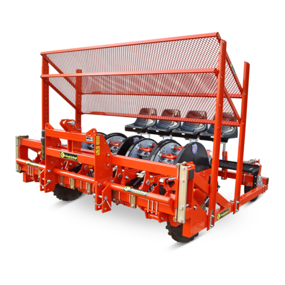
Page 7: Main Parts Wolf Pro
TECHNICAL INFORMATION Main parts WOLF PRO The illustration shows the work vehicle with three planting units. UN41 0768NQ A) Structure for attaching to the three-point hitch on a F) Dispenser tractor G) Protective skid B) RH driving wheel H) Plastic mulch pressing skid (for planting through... -
Page 8: Main Parts (Wolf Pro Compact)
25÷200 Planting unit N° Tyre pressure levels Weight 1180 1380 Main parts (WOLF PRO COMPACT) UN41 0770NQ A) Frame H) Structure for attaching to the three-point hitch on a tractor B) RH driving wheel L) Dispenser C) LH driving wheel... -
Page 9: Drilling Cups Arrangement
TECHNICAL INFORMATION Technical characteristics (WOLF PRO COMPACT) 2285 2000 2000 WOLF PRO COMPACT/ 2 WOLF PRO COMPACT/ 3 2285 2500 3000 WOLF PRO COMPACT/ 4 WOLF PRO COMPACT/ 5 2285 3500 WOLF PRO COMPACT/ 6 UN41 0771NQ Specifications WOLF PRO... -
Page 10: Plant Spacing Range
TECHNICAL INFORMATION The figure shows the housing references on the control disk (A). UN41 0772NQ The chart shows the layout of the cups and phasing units on the dispenser. Number of cups Cups housing reference Phasing units n. Phasing units housing reference Plant spacing range The distance between one seedling and the next one (plant spacing) depends on the number of drilling cups... -
Page 11: Optional Accessories (Wolf Pro)
Hydraulic row tracers with discs WOLF PRO unit watering device Watering device for WOLF PRO 1-3-row machine Watering device for WOLF PRO 4-6-row machine (250 cm additional, screw-fastened frame only) Raised planting unit locking kit WOLF PRO front compactor roller, Ø 285 x 180... -
Page 12: Declaration Of Conformity
Hydraulic row tracers with discs WOLF PRO unit watering device Watering device for WOLF PRO 1-3-row machine Watering device for WOLF PRO 4-6-row machine (250 cm additional, screw-fastened frame only) Raised planting unit locking kit WOLF PRO front compactor roller, Ø 250 x 180... -
Page 13: Guards
TECHNICAL INFORMATION Guards WARNING Never use the machine without the safety guards. The work vehicle is fitted with guards covering the transmission components to prevent accidental contact with the moving parts. The illustration shows the safety casings (A - B - C - D - E - F - G) fitted to protect the moving parts. -
Page 14: Safety Information
TECHNICAL INFORMATION A) Hazard plate: switch off the tractor; remove the igni- F) Hazard plate: risk of entanglement, dragging, and tion key and store in a safe place before carrying out crushing of the upper limbs. any type of work on the work vehicle. G) Information plate: this indicates rotation of the part B) Hazard plate: do not remain on the seat with the to which the plate is applied, showing the direction... -
Page 15: Information Concerning Handling And Installation
The illustration shows the type of packing most com- To contain packing as far as possible, the machine is de- monly used. UN41 0776NQ Approximate packing dimensions WOLF WOLF WOLF WOLF WOLF WOLF PRO/2 PRO/1 PRO/3 PRO/4 PRO/5 PRO/6 Parcels n° Approximate packing dimensions WOLF PRO... -
Page 16: Unpacking And Assembly
The packing materials must be appropriately disposed During unpacking, check that the components are in of or recycled in accordance with the laws in force. The illustration shows a basic assembly diagram of the WOLF PRO work vehicle assembly. WOLF PRO/1 WOLF PRO/2... - Page 17 INFORMATION CONCERNING HANDLING AND INSTALLATION The illustration shows a basic assembly diagram of the WOLF PRO COMPACT work vehicle assembly. WOLF PRO COMPACT/2 WOLF PRO COMPACT/3 WOLF PRO COMPACT/4 WOLF PRO COMPACT/5 WOLF PRO COMPACT/6 UN41 0779NQ English language Use and maintenance...
-
Page 18: Lifting The Wolf Compact Work Vehicle
(see “Technical information”). gravity. For models WOLF PRO/1, WOLF PRO/3, WOLF PRO/5, the seat must be removed to allow the lifting means to be Lifting operations must be carried out using suitable fitted. -
Page 19: Installing The Plastic Mulch Pressing Skid
INFORMATION CONCERNING HANDLING AND INSTALLATION UN41 0781NQ 3) Check that the pin (B) is secured by the lock pin (C) Proceed as outlined below. and that the chains are fastened stably to the frame 1) Use the specific tool (A) provided with the work vehi- (D). -
Page 20: Adjustment Information
ADJUSTMENT INFORMATION Safety advice for the adjustments Maintenance and adjustment work must be car- engaged, ignition key removed, and adopting all the ried out with the work vehicle on flat and compact necessary safety measures required to work safely. ground, with the tractor engine off, parking brake Planting depth adjustment Proceed as outlined below. -
Page 21: Adjusting The Packing Wheel Scraper
ADJUSTMENT INFORMATION To change the distance of the packing wheels, carry out the To change the tilt of the packing wheels, carry out the op- operations described. erations described. 1) Loosen the screws (B). 1) Loosen the screws (E - F). 2) Move the packing wheel (A). -
Page 22: Adjusting The Row Spacing
ADJUSTMENT INFORMATION Adjusting the row spacing Planting in Planting through bare ground plastic mulch UN41 0808ER To plant the seedlings in bare ground, adjust the WARNING planting units so that the seedlings are kept “C” cm Secure the work vehicle in position (lifted off the 10 - 12 away from tractor wheel. -
Page 23: Adjusting The Automatic Safety Release Function
ADJUSTMENT INFORMATION Proceed as outlined below. 1) Loosen the screws (A). 2) Move the cam (B) to the required position. 3) Tighten the screws (A). 4) Carry out the same procedures to adjust the other cams. NOTICE All cams must be set in the same position. UN41 0788NQ Protection skid adjustment The protection skid serves to prevent any root balls from... -
Page 24: Information For Use
ADJUSTMENT INFORMATION Adjusting the tray loader shelves The shelves can be adjusted heightwise, they can be Adjust the shelves according to the size of seedlings, po- moved either farther apart or closer together, and the sitioning them so that the operator is as comfortable as tilt angle can also be altered. -
Page 25: Description Of The Controls
INFORMATION FOR USE Description of the controls WOLF PRO WOLF PRO COMPACT WOLF PRO COMPACT UN41 0793NQ A) Knob: this is used to adjust the planting depth (see C) Lever: this is used to change the position of the sup- page 16). -
Page 26: Disabling The Planting Unit
Seat positioning Poor work posture will tire the operator and could lead WOLF PRO WOLF PRO COMPACT to mistakes being made; therefore, before starting work, adjust the seat and secure it in the position that offers maximum comfort. Proceed as outlined below. -
Page 27: Plant Changeover
Always fit the first cup in the position on the dispens- disassembly but proceeding in reverse order. er marked with (1). Planting procedure WOLF PRO COMPACT WOLF PRO WOLF PRO COMPACT WOLF PRO UN41 0797NQ English language Use and maintenance... -
Page 28: Night-Time Work Or Poor Visibility Conditions
(for the ( load applied to the ground)”, on page 17). WOLF PRO COMPACT machines) must be touching the 11) Position the trays (E) safely in the tray holder. ground and the tractor lift must be fully lowered. -
Page 29: Transit On Public Roads
INFORMATION FOR USE Transporting the work vehicle Units which are narrower than the maximum width al- WARNING lowed by the Highway Code can be loaded , coupled to For work vehicle loading/unloading, use lifting the tractor, onto suitable means of transport using load- equipment with a suitable capacity for the load to be ing ramps. -
Page 30: Maintenance Information
INFORMATION FOR USE Prolonged disuse of the work vehicle If the work vehicle is not due to be used for long periods, 5) Grease the parts that require lubrication (see “Lubri- proceed as follows. cation points diagram”). 6) Park the machine carefully on flat ground in a dry 1) The machine thoroughly, taking care to remove any area protected from the weather. -
Page 31: Check Of Nuts And Bolts Tightening Torque
MAINTENANCE INFORMATION Check of nuts and bolts tightening torque Check that the main fixing nuts and bolts are tight. torque (see the “Nuts and bolts tightening torques chart”). If the bolts are loose tighten them to the prescribed Cleaning the work vehicle Clean the work vehicle with a high-pressure water jet wastewater;... -
Page 32: Lubrication Diagram
MAINTENANCE INFORMATION Lubrication diagram Lubricate the parts shown at the times and in the ways the lubricant. specified. Use universal grease for traction in farming and industri- Before lubricating, clean the components concerned al machinery, which is water-repellent with a 180° drop and the greasing nipples to prevent contamination of point. -
Page 33: Information Concerning Replacements
MAINTENANCE INFORMATION Nuts and bolts tightening torques chart Nuts and bolts tightening torques Resistance class Resistance class Resistance class Thread diameter Thread pitch (mm) 8.8 (Nm) 10.9 (Nm) 12.9 (Nm) 13.0 16.0 1,25 23.0 32.0 39.0 M 10 46.0 64.0 77.0 M 12 1,75... -
Page 34: Replacing The Driving Wheels Chain
INFORMATION CONCERNING REPLACEMENTS Replacing the driving wheels pinion UN41 0801NQ Proceed as outlined below. Unscrew the screw (L). Move the lever (E) to lift the wheel in order to slack- Remove the pinion (M). en off the chain. Fit the new pinion and tighten the screw (L). 10) Fit a new chain on the pinions and the tensioner. -
Page 35: Replacing The Planting Unit Chain
INFORMATION CONCERNING REPLACEMENTS Proceed as outlined below. CAUTION Move the lever (E) to lift the wheel in order to slack- The tensioner could move unexpectedly, causing in- en off the chain. jury to the hands. Loosen the knobs (A). Proceed with the utmost caution. Remove the casing (B). -
Page 36: Replacing The Packing Wheel Scraper
INFORMATION CONCERNING REPLACEMENTS Replacing the packing wheel scraper Proceed as outlined below. Loosen the screws (A). Open out the packing wheels so that the wheel can be removed. Tighten the screws (A). Take out the lock pin (B). Remove the packing wheel (C). Remove the circlip (D). - Page 38 VIA GUIZZARDI, 38 40054 BUDRIO (BO) - ITALY TEL. +39 051 80 02 53 - FAX +39 051 69 20 611...
Need help?
Do you have a question about the WOLF PRO and is the answer not in the manual?
Questions and answers