Advertisement
Quick Links
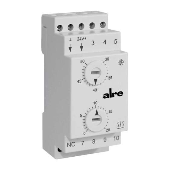
KTRRN-267.014
Normschienen-Klimaregler mit DC-Polumschaltung zur Ansteuerung von Peltierelementen mit Lüfter
Climate controller for DIN rail installation with DC pole changeover for the triggering of Peltier elements and fans
Sicherheitshinweis
Dieses Gerät darf nur durch eine Elektrofachkraft geöffnet und gemäß dem
entsprechenden Schaltbild im Gehäusedeckel / auf dem Gehäuse / in der Bedie-
nungsanleitung installiert werden. Dabei sind die bestehenden Sicherheitsvor-
schriften zu beachten.
Achtung! Der Betrieb in der Nähe von Geräten, welche nicht den EMV-Richtlini-
en entsprechen, kann zur Beeinflussung der Gerätefunktionen führen. Nach der
Installation ist der Betreiber, durch die ausführende Installationsfirma, in die
Funktion und Bedienung der Regelung einzuweisen. Die Bedienungsanleitung
muss für Bedien- und Wartungspersonal an frei zugänglicher Stelle aufbewahrt
werden.
1. Anwendung
Dieser Regler wurde speziell für die Ansteuerung von Peltiermodulen mit
Lüfter zur Klimatisierung von Schaltschränken entwickelt. Für andere vom Her-
steller nicht vorherzusehende Einsatzgebiete sind die dort gültigen Sicherheits-
vorschriften zu beachten. Eignung hierfür siehe Punkt 8.
2. Funktion
Der KTRRN verfügt über zwei Regelbereiche für die Funktionen Heizen und
Kühlen. Im unteren Einstellbereich wird der Schaltpunkt für Heizen, im oberen
Einstellbereich der Schaltpunkt für Kühlen gewählt. Die Einstellbereiche sind
durch einen Bereich von 10 K getrennt. Somit ist immer eine Neutrale Zone von
mindestens 10 K gegeben und eine Falscheinstellung/Überschneidung der
Schaltpunkte durch den Installateur wird vermieden. Unterschreitet die Tempe-
ratur den eingestellten Heiz-Schaltpunkt, schaltet der Regler den Außenlüfter
ein und aktiviert das Peltierelement, wobei die Gleichstromrichtung eine Behei-
zung des Schaltschranks bewirkt. Wird der eingestellte Kühl-Schaltpunkt über-
schritten, wird ebenfalls der Außenlüfter eingeschaltet und das Peltierelement
mit entgegengesetzter Gleichstromrichtung aktiviert. Die entgegengesetzte
Gleichstromrichtung bewirkt die Kühlung des Schaltschranks.
3. Installation / Montage
Die Montage des Reglers erfolgt auf einer DIN Normschiene. Hierzu wird der
Regler mit den oberen Haken eingehängt und anschließend durch Aufdrücken
auf die Normschiene eingeschnappt. Zum Abnehmen des Reglers von der
Normschiene sind mittels Schlitz-Schraubendreher zuerst die oberen Haken
durch Herausziehen der Lasche zu lösen und der Regler auszuhängen. Zur
Montage auf einer Blechwand oder einem Profilrahmen wird das Montageset
JZ-13 (siehe Punkt 5.) verwendet. Die Einbaulage bei Verwendung des internen
Sensors erfolgt senkrecht in Leserichtung der Klemmenbedruckung. Nach der
Montage ist der Regler wie im Anschluss-Schaltbild zu verdrahten (vgl. Punkt
6.). Achtung! Die Masse der Versorgungsspannung darf nicht mit der Masse
der Fühler verbunden werden. Ein Zusammenschluss oder eine Verwechslung
führt zur Zerstörung des Reglers. An Stelle der Klemme 6 (mit NC bedruckt) be-
findet sich der interne Fühler. Es ist darauf zu achten, hier keinen Schrauben-
dreher einzuführen, um den Fühler nicht zu beschädigen. Muss der Regler aus
Platzgründen in der Nähe von Wärme- oder Kältequellen montiert oder kann er
aus anderen Gründen nicht an der eigentlichen Messstelle installiert werden,
kann ein Fernfühler angeschlossen werden (vgl. Punkt 5. und 6.). Bei Verwen-
dung des externen Fühlers ist die Einbaulage des Reglers beliebig. Um eine
Überhitzung des Reglers und der Anschlussleitungen zu vermeiden, sind die
unter Punkt 4. angegebenen Leitungsquerschnitte genauesten zu beachten!
4. Technische Daten
Versorgungsspannung:
Schaltvermögen
Ausgang Peltierelement:
Ausgang Lüfter:
Leistungsaufnahme:
Regelbereich Heizen:
Regelbereich Kühlen:
Schaltdifferenz (Hysterese):
Fühler:
Fühlertoleranz:
Schutzklasse:
Schutzart:
Zulässige Umgebungstemperatur: -10 ... 55°C, Achtung! Ab 30°C oder höher 10A
Lagertemperatur:
Zulässige Feuchte:
Elektrische Anschlüsse:
Gewicht:
Gehäusewerkstoff und Farbe:
Montageart:
Stand 06.2008 (ÄA08/134) JD
24V DC
16A Relaisausgang, Achtung! Ab 10A oder höher
30°C darf nicht mit 1,5 mm
2
sondern muss mit
dem nächst höheren Querschnitt 2,5 mm
verdrahtet werden
2(1)A Relaisausgang
ca.1W
0 ... 20°C
30 ... 50°C
ca.1K
intern oder externer NTC 2 K
ca.1K
III
IP20
Anschlussquerschnitt 2,5 mm
2
beachten
-20 ... 70°C
max. 95%rH, nicht betauend
Schraubklemmen 0,5 ... 2,5 mm
2
105 g
Kunststoff ABS, Lichtgrau RAL 7035
DIN Normschiene 35 mm
Safety information
D
No persons other than expert electricians only must open this device in due
compliance with the wiring diagram shown in the housing cover / on the
housing / represented in the corresponding operating instructions.
Caution! The operation of the controller in the vicinity of other devices that do
not comply with the EMC directives may affect its functions. The company char-
ged with the installation of the device must, after the completion of the installa-
tion works, instruct the user of the control system into its functions and in how
to operate it correctly. These operating instructions must be kept at a place that
can be accessed freely by the operating and/or servicing personnel in charge.
1. Application
This temperature controller has been specially devised for the triggering of Peltier
modules and fans that are usually applied in connection with the conditioning of
the air in switch cabinets. Regarding other applications not to be foreseen by the
manufacturer of this device, the safety standards concerning these applications
need to be followed and adhered to. Regarding the aptitude of the device for any
such other application, please refer to section 8 herein (Warranty).
2. Functional description
The KTRRN is equipped with two control ranges, i.e. one each for the function
"heating" and "cooling". The selection of the "heating" switch point takes place
in the lower section of the setting range, while the one of the "cooling" switch
point is effected in the upper section of the range. The setting ranges are sepa-
rated by a span that is equivalent to 10 K. A neutral zone of at least 10 K is thus
created. Installers charged with the setting and installation of the device can
hence no longer misadjust the switch points or erroneously set them in an
overlapping manner. In the event the temperature level falls below the adjusted
heating switch point, the controller activates both the external fan and the
Peltier element. The direction of the current that flows through the Peltier ele-
ment triggers, during the time this is the case, the heating of the switch cabinet.
In the event the adjusted cooling switch point is being underrun, the external
fan is turned on too and the Peltier element activated through the then opposed
direction of the direct current that flows through it. Once activated this way, the
Peltier element triggers the control of the cooling operations inside the switch
cabinet.
3. Mounting / installation
The controller is intended for the installation on a DIN standard rail. To install it,
the controller must first be hung up on the rail using the upper hooks provided
for this purpose. After that, it can be snapped onto the standard rail by pressing
against the device. The controller can be removed again from the rail by loose-
ning the upper hooks by means of a slot screwdriver, i.e. by pulling the brackets
out after which the device can be unhooked. The installation set JZ-13 (see
section 5.) will be required for the installation of the device on a sheet metal
wall or on a profiled frame. If using the internal sensor, the device needs to be
installed vertically, scilicet in the direction the text imprints on the terminals are
to be read. The controller must, after its installation, be wired as shown in the
connection diagram (see section 6.).
Caution! The ground potential of the supply voltage must not be connected to
the ground potential of the sensor. Connecting both of these ground potentials
or their confusion leads to the destruction of the device! The internal sensor is
located in the position of the terminal 6 (imprinted with the letters "NC"). Make
sure not introduce a screwdriver here as, if otherwise, the sensor could get da-
maged. If, for reasons of space, the controller needs to be installed near to heat
or cold sources or if it cannot be installed at the actually required measuring
point, a remote senor too can be connected (see sections 5. and 6.). If using an
external sensor, the controller can be installed in any position. To prevent any
overheating of the temperature controller and connecting leads, an exact note is
to be taken of the lead cross-sections specified in Item 4!
4. Technical data
Supply voltage:
Breaking capacity
Output of Peltier element:
2
Output of fan:
Power input:
Control range – heating:
Control range – cooling:
Differential (Hysteresis):
Sensor:
Sensor tolerance:
Protection class:
Degree of protection:
Safe ambient temperature:
Storage temperature:
Admissible humidity:
Electrical connections:
Weight:
Housing material and colour:
Type of installation:
24V DC
16A relay output, Caution! Upwards of 10A or in excess
of 30°C, wiring is not to be of the 1.5 mm
cross-section but of the next higher one of 2.5 mm
2(1)A relay output
1W
0 ... 20°C
30 ... 50°C
1K
internally or externally NTC 2K
1K
III
IP20
-10 ... 55°C, Caution! Note the need for 2.5 mm
connecting cross-section above 30°C or in excess of
10A
-20 ... 70°C
max. 95% r.h., non-dewing
Screw-type terminals 0.5 ... 2.5 mm
2
105 g
ABS plastic, RAL 7035 light grey
DIN standard 35 mm rail
GB
2
2
2
5 21 395 01
Advertisement

Related Manuals for alre KTRRN-267.014


Summary of Contents for alre KTRRN-267.014
- Page 1 KTRRN-267.014 Normschienen-Klimaregler mit DC-Polumschaltung zur Ansteuerung von Peltierelementen mit Lüfter Climate controller for DIN rail installation with DC pole changeover for the triggering of Peltier elements and fans Sicherheitshinweis Safety information Dieses Gerät darf nur durch eine Elektrofachkraft geöffnet und gemäß dem No persons other than expert electricians only must open this device in due entsprechenden Schaltbild im Gehäusedeckel / auf dem Gehäuse / in der Bedie-...
- Page 2 Gewährleistung. Änderungen vorbehalten. refuse to grant any warranty with regard thereto. Subject to change without notice. ALRE-IT Regeltechnik GmbH – Richard-Tauber-Damm 10 – D-12277 Berlin – Tel.: +49 (0)30/39984-0 – Fax: +49 (0)30/391 70 05 – mail@alre.de – www.alre.de...
Need help?
Do you have a question about the KTRRN-267.014 and is the answer not in the manual?
Questions and answers