Table of Contents
Advertisement
Quick Links
FETR 101.700
Elektronischer Unterputz-Fußbodentemperaturregler im Flächenschalterrahmen mit Inneneinstellung (Behördenvariante)
Flush mounted floor temperature controller with internal set point setting facility (variant for use in public buildings)
Sicherheitshinweis!
Dieses Gerät darf nur durch eine Elektrofachkraft geöffnet und gemäß dem entsprechen-
den Schaltbild im Gehäusedeckel / auf dem Gehäuse / in der Bedienungsanleitung instal-
liert werden. Dabei sind die bestehenden Sicherheitsvorschriften zu beachten.
Achtung! Der Betrieb in der Nähe von Geräten, welche nicht den EMV-Richtlinien ent-
sprechen, kann zur Beeinflussung der Gerätefunktionen führen. Nach der Installation ist
der Betreiber, durch die ausführende Installationsfirma, in die Funktion und Bedienung
der Regelung einzuweisen. Die Bedienungsanleitung muss für Bedien- und Wartungs-
personal an frei zugänglicher Stelle aufbewahrt werden.
1. Anwendung
Dieser elektronische Zweipunktregler wurde speziell zur Regelung elektrischer oder
Warmwasser-Heizungen/Zusatzheizungen für Fußböden und anderer Oberflächentempe-
riersysteme entwickelt. Der FETR 101.700 verfügt über eine interne Sollwerteinstellung.
Dadurch eignet er sich besonders zur Installation in Behörden, Banken, Schulen, Kinder-
gärten, Museen und ähnliche Gebäude in denen eine Sollwertverstellung durch unbefug-
te Personen verhindert werden soll. Für andere vom Hersteller nicht vorherzusehende
Einsatzgebiete sind die dort gültigen Sicherheitsvorschriften zu beachten. Eignung hier-
für siehe Punkt 10. Gewährleistung.
2. Funktion
Der Regler misst mit einem in den Fußboden eingebrachten Fühler die Temperatur und
regelt diese mit einer Schaltdifferenz von ca.1K auf den eingestellten Sollwert. Aus
dieser Regelung ergibt sich eine Oberflächentemperatur, die hauptsächlich durch den
Aufbau des Fußbodens bestimmt wird. Bei elektrischen Heizungen ist darauf zu achten,
dass diese auch bei Dauerbetrieb den Oberflächenaufbau nicht überhitzen können.
Achtung! Bei Oberflächen, ausgeführt als Sitzmöbel oder Stellfläche, ist darauf zu
achten, dass die eingestellte Temperatur nicht zu einer Gesundheitsgefährdung von
Personen oder Entflammung von Gegenständen führen kann. Die rote Lampe zeigt
die aktive Heizung an. Bei Fühlerbruch, Fühlerkurzschluss oder einer Fühlertemperatur
unter -15°C (entspricht Fühlerbruch) wird die Heizung ausgeschaltet. Wird an der
Klemme
die Phase geschaltet, senkt der Regler den eingestellten Sollwert um ca. 5 K
ab. Die grüne Lampe zeigt diesen Energiesparmodus an.
3. Montage und Installation
Je nach Gerätetyp oder Verpackungsgröße, wird das Gerät entweder geschlossen oder
der schnelleren Montage wegen geöffnet ausgeliefert. Das Gerät mit dem 50 x 50 mm
Gehäusedeckel ist mittels Zwischenrahmen der Schalterhersteller nach DIN 49075 in
nahezu alle Schalterprogramme integrierbar. Das Gerät mit dem 55 x 55 mm Gehäuse-
deckel ist ebenfalls für diverse Schalterprogramme geeignet. Bei Mehrfachrahmen ist der
Regler immer an unterster Stelle zu montieren. Zum Öffnen des Reglers ist die Schraube
nach Abziehen der Schraubenabdeckung zu lösen und die Reglerkappe inklusive Rahmen
abzunehmen. Nach elektrischem Anschluss und Montage in die UP-Dose, ist der Regler
in umgekehrter Reihenfolge wieder zu schließen. Einstellen der Solltemperatur siehe
nachfolgende Darstellung.
Der Fühler führt Netzspannungspotential und darf nur mit dem Leitungstyp H05VV-F
verlängert werden. Die nach EN 60730-1 vorgeschriebene doppelte Isolierung muss auch
an der Verbindungsstelle eingehalten werden. Es ist darauf zu achten, dass die Fühler-
leitung nicht parallel zu netzspannungsführenden Leitungen verlegt wird. Ist die Parallel-
verlegung nicht zu vermeiden, muss eine geschirmte Leitung verwendet und der Schirm
auf die Fühlermasse gelegt werden. Um einen Austausch eines defekten Fühlers zu
gewährleisten, muss der Fühler inklusive Fühlerleitung reversibel in einem Leerrohr
verbaut werden. Zum Verschließen des Leerrohres im Estrich wird die Schutzhülse THF
verwendet (vgl. Punkt 6. Zubehör). Um eine optimale Wärmeverteilung im Fußboden zu
erreichen, muss der Fühler mittig zwischen zwei Heizleitern positioniert werden. Bei
Warmwasser-Beheizten Oberflächen sind stromlos geschlossene Ventile zu verwenden.
Gegebenenfalls benötigte Temperaturbegrenzungen müssen zusätzlich installiert werden.
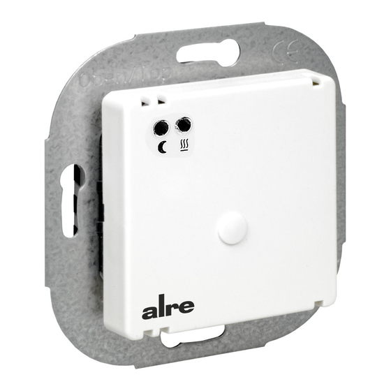
Regler 50 x 50 mit Alre-Rahmen
Controller (50 x 50) with Alre type frame
Stand 1 1.2009 (ÄM 09/124) MT
Safety information!
D
No persons other than expert electricians only must open this device in due compliance
with the wiring diagram shown in the housing cover / on the housing / represented in the
corresponding operating instructions. All expert electricians committed to the execution
of any such works must comply with the relevant safety regulations currently operative
and in force.
Caution! The operation of the controller in the vicinity of other devices that do not
comply with the EMC directives may affect its functions. The company charged with the
installation of the device must, after the completion of the installation works, instruct the
user of the control system into its functions and in how to operate it correctly. These
operating instructions must be kept at a place that can be accessed freely by the opera-
ting and/or servicing personnel in charge.
1. Application
This electronic two-point controller has been specially devised for the control of addi-
tional electric or warm-water systems that serve for the heating of floors. It can also
be applied for the control of other surface temperature equalization systems. The
FETR 101.700 has been equipped with an internal set point setting facility. This is why
the device is specially suited for the installation in public or bank buildings, schools, pre-
schools, museums or other buildings of a similar nature. Regarding other applications
not to be foreseen by the manufacturer of this device, the safety standards concerning
these applications need to be followed and adhered to. Regarding the aptitude of the
device for any such other application, please refer to section 8. herein (Warranty).
2. Functioning
The controller measures, based on the data delivered to it by a sensor installed in the
floor, the existing floor temperature and controls it with a switching difference of approx.
1K. The control operations thus performed result in a surface temperature which is
mainly determined by the structure and composition of the related floor. With electric
heating lines care must be taken to ensure that they cannot superheat the surface struc-
ture, even if operated continuously.
Caution! With heated surfaces that have been designed as sitting furniture or that provide
special storing surfaces, care must be taken to ensure that the adjusted temperature
does not lead to health risks or to the inflammation of objects. The active state of the
heating system is indicated by the red lamp that has been provided for this purpose. The
heating system is deactivated in the event of a sensor breakdown or sensor short-circuit
and also in the event the sensor measures a temperature below -15°C (equivalent to a
sensor breakdown). When connecting the phase to the terminal
creases the adjusted set value by approx. 5 K. The green lamp indicates the active state of
this energy economizing mode.
3. Mounting and installation
The controller is, depending on the type version of the device or size of the package used
for it, either delivered in closed or, in order to facilitate its fast installation, also in opened
condition. The device with the 50 x 50 mm housing cover can be integrated into almost
all currently available flush switch installation frame systems when using DIN 49075
compliant intermediate frames. The device with the 55 x 55 mm housing cover is also
suited for use with different commercially available switch lines. If using multiple frames,
the controller must always be mounted in the lowest position. The controller can be
opened after the removal of the screw-on cover. Once this has been done, a screwdriver
must to be applied to loosen the screw that is visible now and the controller cover inclu-
ding frame be removed. After that, the controller cap can be removed along with the
frame. After its electrical connection and installation in an UP box, the housing can be
closed again in inverse order. Regarding the setting of the set temperature, please see
the illustration below.
The sensor carries line voltage potential and may only be extended by means of an
H05VV-F compliant cable. The double insulation required by EN 60730-1 needs to be ob-
served at the connection point too. Care must be taken to ensure that the sensor line is
not laid in parallel to line voltage carrying cables or lines. Where parallel laying cannot be
avoided, a shielded line must be used and the shielding be connected to the sensor
mass. In order to ensure the easy replacement of a defective sensor, the sensor inclu-
ding its line needs to be laid inside an empty conduit in a replaceable manner. The pro-
tecting sleeve, type THF, serves for the closing of the empty conduit that has been con-
cealed in the related surface structure (see section 6., Accessories). The sensor must, in
order to obtain an optimal distribution of the heat in the floor, be positioned centrically
between two heating conductors. With warm-water heated surfaces, normally closed
valves are to be used. Possibly required temperature limiters need to be installed in addi-
tion.
Regler 50 x 50 mit Beispiel-Rahmen und Zwischenrahmen
Controller (50 x 50) with sample frame and intermediate frame
Interne Temperatureinstellung 1 ... 5 entspricht ca.10 ... 50° im Fühlerbereich
The internal temperature setting range 1 ... 5 equals to a sensor range of 10 ... 50°
GB
, the controller de-
5 21 583 01
Advertisement
Table of Contents

Subscribe to Our Youtube Channel
Related Manuals for alre FETR 101.700


Summary of Contents for alre FETR 101.700
- Page 1 The Dadurch eignet er sich besonders zur Installation in Behörden, Banken, Schulen, Kinder- FETR 101.700 has been equipped with an internal set point setting facility. This is why gärten, Museen und ähnliche Gebäude in denen eine Sollwertverstellung durch unbefug- the device is specially suited for the installation in public or bank buildings, schools, pre- te Personen verhindert werden soll.
- Page 2 We refuse to grant any warranty with regard thereto. Subject to change without notice. ALRE-IT Regeltechnik GmbH · Richard-Tauber-Damm 10 · D-12277 Berlin Tel.: +49(0)30/ 399 84-0 · Fax: +49(0)30/ 391 70 05 · mail@alre.de · www.alre.de...
Need help?
Do you have a question about the FETR 101.700 and is the answer not in the manual?
Questions and answers