Table of Contents
Advertisement
Quick Links
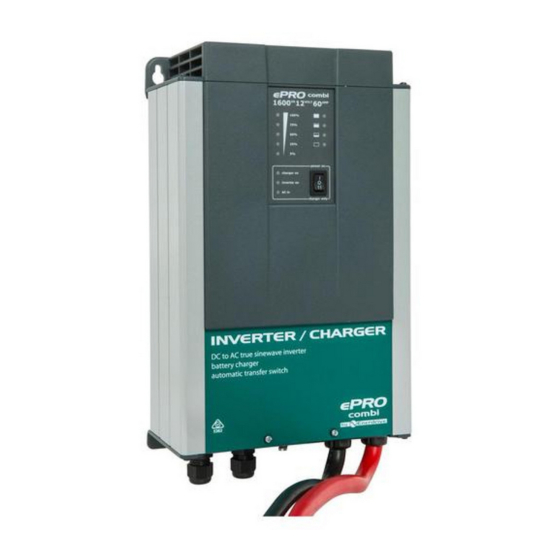
INVERTER / CHARGER
DC to AC true sinewave inverter
programmable automatic battery charger
Owner's Manual
EPC 1600-12 ePRO Combi 12V / 60Amp
EPC 2000-12 ePRO Combi 12V / 80Amp
EPC 3000-12 ePRO Combi 12V / 120Amp
automatic transfer switch
EPC 1800-24 ePRO Combi 24V / 35Amp
EPC 2500-24 ePRO Combi 24V / 50Amp
EPC 3500-24 ePRO Combi 24V / 70Amp
Advertisement
Table of Contents

Related Manuals for Enerdrive ePRO Combi Series


Summary of Contents for Enerdrive ePRO Combi Series
- Page 1 INVERTER / CHARGER DC to AC true sinewave inverter programmable automatic battery charger automatic transfer switch Owner’s Manual EPC 1600-12 ePRO Combi 12V / 60Amp EPC 1800-24 ePRO Combi 24V / 35Amp EPC 2000-12 ePRO Combi 12V / 80Amp EPC 2500-24 ePRO Combi 24V / 50Amp EPC 3000-12 ePRO Combi 12V / 120Amp EPC 3500-24 ePRO Combi 24V / 70Amp...
- Page 2 Important Please be sure to read and save the entire manual before using your Enerdrive ePRO Inverter / Charger. Misuse may result in damage to the unit and/or cause harm or serious injury. Read manual in its entirety before using the unit and save manual for future reference.
- Page 3 Enerdrive ePRO Combi EPC 1600-12 to EPC 3500-24 inverter/charger owner’s manual © 2012- 2014 Enerdrive . All rights reserved. No part of this document may be reproduced in any form or disclosed to third parties without the express written permission of Enerdrive Pty Ltd, Unit 11, 1029 Manly Road Tingalpa, Queensland, Australia 4173.
-
Page 4: Table Of Contents
5. CHARGER OPERATION ................. 26 Charge programs ............... 26 Equalizing a ooded battery ..........29 6. TROUBLESHOOTING GUIDELINE ............32 7. TECHNICAL SPECIFICATIONS ............. 38 8. WARRANTY CONDITIONS ..............44 9. NOTES ....................... 46 Page 4 Enerdrive ePRO Inverter / Charger Owners Manual... -
Page 5: Introduction
CAUTION This section contains important safety information for the Enerdrive ePRO Combi. Each time, before using the Enerdrive ePRO Combi, READ ALL instructions and cautionary markings on or provided with the inverter, and all appropriate sections of this guide. The Enerdrive ePRO Combi contains no user serviceable parts. - Page 6 WARNING FIRE AND/OR CHEMICAL BURN HAZARD Do not cover or obstruct any air vent openings and/or install in a zero- clearance compartment. Page 6 Enerdrive ePRO Inverter / Charger Owners Manual...
- Page 7 AC sockets at home. WARNING EXPLOSION HAZARD! DO NOT use the Enerdrive ePRO Combi in the vicinity of ammable fumes or gases (such as gas bottles or large engines). AVOID covering the ventilation openings. Always operate unit in an open and well ventilated area.
-
Page 8: Description
2. Description The Enerdrive ePRO Combi is an all-in-one combination of a DC to AC true sinewave inverter, an advanced multi-stage battery charger and a high speed AC transfer switch. All this is built into one compact, yet installer friendly enclosure. Besides these three main functions, there are several unique features o ered as well. - Page 9 Combi by external events. • Temperature controlled fans, to guarantee silent operation under less than full load conditions. • Temperature compensated battery charging, using the standard supplied battery temperature sensor for maximum battery lifetimes. Enerdrive ePRO Inverter / Charger Owners Manual Page 9...
-
Page 10: Configuring The Epro Combi
3. Con guring The Enerdrive ePRO Combi 3.1 General The ePRO Combi can be con gured in two ways. Using the DIP switches located in the connection bay, a small selection of basic settings can be made. In most cases this will be su cient to quickly setup the unit for typical applications. -
Page 11: Factory Default Parameter Settings
The table below shows an overview of the most relevant factory parameter settings, as stored in the ePRO Combi. These settings are based on an average application. Enerdrive cannot guarantee that these are correct for your speci c application. Please check all parameters carefully, especially the battery charging voltages. - Page 12 Input frequency range which is accepted by the ePRO Combi. Can be set to full range (45Hz – 65Hz), or to a smaller range within the 45Hz lower and 65Hz upper boundaries. Con gurable by Dashboard Page 12 Enerdrive ePRO Inverter / Charger Owners Manual...
- Page 13 This parameter can be set On or O . Con gurable by DIP switch (DIP 7) and Dashboard Parameter Ground switch Value Enabled Enerdrive ePRO Inverter / Charger Owners Manual Page 13...
- Page 14 AC input source inverter transfer time of less than 5ms, while being reasonably immune against distorted AC input signals. Con gurable by Dashboard Parameter Battery type / Charge program Value Page 14 Enerdrive ePRO Inverter / Charger Owners Manual...
- Page 15 (temporarily) reduce the charger current share, in the total amount of current owing through the AC input of the ePRO Combi. Con gurable by Dashboard and Universal Remote Control Enerdrive ePRO Inverter / Charger Owners Manual Page 15...
-
Page 16: Dip Switch Settings Overview
Low battery protect ON = Low battery protect is on OFF = Low battery protect is o (immediate inverter shutdown when the battery voltage is < 8.0V) Factory setting = ON Page 16 Enerdrive ePRO Inverter / Charger Owners Manual... - Page 17 Absorption voltage = set by Dashboard Float voltage = set by Dashboard AC Input Power Boost ON = AC Input Power Boost on OFF = AC Input Power Boost o Factory setting = OFF Enerdrive ePRO Inverter / Charger Owners Manual Page 17...
- Page 18 Factory setting = ON Models : ePRO Combi 2000-3500 Ground switch/relay ON = Ground switch is enabled OFF = Ground switch is disabled Models : ePRO Combi 2000-3500 only Reserved Factory setting = OFF Page 18 Enerdrive ePRO Inverter / Charger Owners Manual...
- Page 19 ‘on’ or ‘charger only’ position. CAUTION Invalid battery type settings can cause serious damage to your batteries and/or connected battery loads. Always consult your battery’s documentation for the correct charge voltage settings. Enerdrive ePRO Inverter / Charger Owners Manual Page 19...
-
Page 20: General Operation
No AC signal will be present at the ePRO Combi output when there is no AC input signal either. Information about the LED indicators on the frontpanel and the di erent error mode codes, can be found in the next chapter. Page 20 Enerdrive ePRO Inverter / Charger Owners Manual... -
Page 21: Epro Combi Led Indicators And Error Modes
2. Mode indicators. Indicate the operating mode of the ePRO Combi, as well as the status of each di erent mode (see explanation over): Enerdrive ePRO Inverter / Charger Owners Manual Page 21... - Page 22 AC input present and within range, ePRO Combi is synchronizing On (green) AC input approved, transfer switch closed On (blinking red) AC input present but out of range On (red) AC transfer switch disabled Page 22 Enerdrive ePRO Inverter / Charger Owners Manual...
-
Page 23: Error Indications
Five ashes in a row Charge program error (only for ‘charger on’ indicator LED). Charge program selection set to Custom, while custom made charge program contains an error or time-out. Enerdrive ePRO Inverter / Charger Owners Manual Page 23... -
Page 24: Programmable Alarm Relay
30Vdc/16A or 250Vac/16A. 4.4 Trigger Input The trigger input o ers a way of externally controlling the behaviour of the ePRO Combi. The trigger input can be connected to an external Page 24 Enerdrive ePRO Inverter / Charger Owners Manual... -
Page 25: Load Requirements In Inverter Mode
Note that at higher ambient temperature levels, the overload capacity of the ePRO Combi will be reduced. Enerdrive ePRO Inverter / Charger Owners Manual Page 25... -
Page 26: Charger Operation
All standard selectable charge programs (using DIP switches 5 and 6), perform a four stage IUoUoP charging process comprising of a “Bulk”, an “Absorption”, a “Float” and a “Pulse” stage. The image below visualizes the four stage charging process : Page 26 Enerdrive ePRO Inverter / Charger Owners Manual... - Page 27 When the battery temperature sensor is installed, the charger automatically compensates the charge voltages against battery temperature. This means that the charge voltages are slightly increased at lower temperatures and decreased at higher temperatures (-30mV/°C Enerdrive ePRO Inverter / Charger Owners Manual Page 27...
- Page 28 Dashboard. Up to 8 di erent stages can be linked together and all individual stages can be con gured extensively. Page 28 Enerdrive ePRO Inverter / Charger Owners Manual...
-
Page 29: Equalizing A Ooded Battery
The internal 2 hours time-out timer of your charger is only intended as a safety feature, but may not be su ciently short to prevent battery damage. Therefore, equalizing a battery is always a process that must continuously be supervised by the user. Enerdrive ePRO Inverter / Charger Owners Manual Page 29... - Page 30 (see images below) for 3 seconds, until all charge status indicators start ashing. Models :EPC 1600-12 to 1800-24 : Models :EPC 2000-12 to 3500-24 : Page 30 Enerdrive ePRO Inverter / Charger Owners Manual...
- Page 31 When these values are correct, you can manually exit the equalization process by pressing the recessed push-button once. The ePRO Combi will then return to the Float stage. Enerdrive ePRO Inverter / Charger Owners Manual Page 31...
-
Page 32: Troubleshooting Guideline
45Hz – 65Hz activate either). (assuming standard settings) Charger mode and/or the AC Enable Charger mode and the AC transfer switch are disabled transfer switch using Dashboard. during setup using Dashboard. Page 32 Enerdrive ePRO Inverter / Charger Owners Manual... - Page 33 Try to lower the ambient is too low. temperature around the ePRO Combi. Charger is operating in the Do nothing. The battery is absorption charging stage. almost fully charged and consumes less current by itself. Enerdrive ePRO Inverter / Charger Owners Manual Page 33...
- Page 34 Inverter is overloaded. Make sure that the total power indicator LED rating of the AC output load ‘inverter on’ is lower than the nominal blinks red twice inverter power rating. per second. Page 34 Enerdrive ePRO Inverter / Charger Owners Manual...
- Page 35 10cm around the unit. Do not obstruct the air ow, place no items on or over the unit. Keep the ePRO Combi away from direct sunlight or heat producing equipment. Enerdrive ePRO Inverter / Charger Owners Manual Page 35...
- Page 36 Output power bar The inverter is overloaded Reduce the AC output load is red (inverter and will shut down after a mode). certain time (depending on the amount of overload) Page 36 Enerdrive ePRO Inverter / Charger Owners Manual...
- Page 37 If none of the above remedies will help to solve the problem you are encountering, then it is best to contact your local Enerdrive distributor for further help and / or possible repair of your Enerdrive ePRO Combi. WARNING: SHOCK HAZARD Do not disassemble the ePRO Combi yourself, there are dangerously high voltages present inside and will also void your warranty.
-
Page 38: Technical Specifications
Protections high/low battery voltage, high temperature, overload, short circuit, high ripple voltage and low AC input voltage DC connections Two wires, length 1.5 meters, 35mm2 AC connections Screw terminals Page 38 Enerdrive ePRO Inverter / Charger Owners Manual... - Page 39 Undervoltage limit is dynamic. This limit decreases with increasing load to compensate the voltage drop across cables and connections. Measured at nominal input voltage and 25°C At higher ambient temperatures, maximum output current shall be reduced automatically Enerdrive ePRO Inverter / Charger Owners Manual Page 39...
- Page 40 AC input voltage DC connections M10 bolt terminals AC connections Screw terminals Enclosure body size 370 x 431 x 132mm Page 40 Enerdrive ePRO Inverter / Charger Owners Manual...
- Page 41 Undervoltage limit is dynamic. This limit decreases with increasing load to compensate the voltage drop across cables and connections. Measured at nominal input voltage and 25°C At higher ambient temperatures, maximum output current shall be reduced automatically. Enerdrive ePRO Inverter / Charger Owners Manual Page 41...
- Page 42 AC input voltage DC connections M10 bolt terminals AC connections Screw terminals Enclosure body size 370 x 431 x 132mm Page 42 Enerdrive ePRO Inverter / Charger Owners Manual...
- Page 43 Undervoltage limit is dynamic. This limit decreases with increasing load to compensate the voltage drop across cables and connections. Measured at nominal input voltage and 25°C At higher ambient temperatures, maximum output current shall be reduced automatically Enerdrive ePRO Inverter / Charger Owners Manual Page 43...
-
Page 44: Warranty Conditions
The limited warranty program is the only one that applies to this unit, and it sets forth all the responsibilities of Enerdrive. There is no other warranty, other than those described herein. Any implied warranty of merchantability of tness for a particular purpose on this unit is limited in duration to the duration of this warranty. - Page 45 Enerdrive within 30 days of the date of purchase will be replaced free of charge. If such a unit is returned more than 30 days but less than two years from the purchase date, Enerdrive will repair the unit or, at its option, replace it, free of charge.
-
Page 46: Notes
Page 46 Enerdrive ePRO Inverter / Charger Owners Manual... - Page 47 Enerdrive ePRO Inverter / Charger Owners Manual Page 47...
- Page 48 Page 48 Enerdrive ePRO Inverter / Charger Owners Manual...
Need help?
Do you have a question about the ePRO Combi Series and is the answer not in the manual?
Questions and answers