
Related Manuals for Enerdrive ePRO Combi


Summary of Contents for Enerdrive ePRO Combi
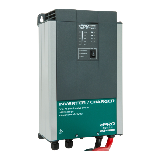
- Page 1 INVERTER/CHARGER OWNERS MANUAL 12V 1600VA 60AMP / 24V 1800VA 35AMP DC to AC true sinewave inverter. Programmable battery charger. Automatic transfer switch...
- Page 2 IMPORTANT Please be sure to read and save the entire manual before using your Enerdrive ePRO Combi. Misuse may result in damage to the unit and/or cause harm or serious injury. Read manual in its entirety before using the unit and save manual for future reference.
-
Page 3: Table Of Contents
3.3 DIP switch settings overview __________________________________________ 10 4. GENERAL OPERATION ____________________________________________________ 12 4.1 Operating the Enerdrive ePRO Combi __________________________________ 12 4.2 Enerdrive ePRO Combi LED indicators and error modes ____________________ 12 4.2.1. Error indications ___________________________________________________ 13 4.3 Alarm relay ________________________________________________________ 14 4.4 Trigger input _______________________________________________________ 14... -
Page 4: Introduction
At the time of this writing, Enerdrive cannot guarantee that all mentioned features in this manual are actually available in your ePRO Combi. Nor can Enerdrive guarantee that all features are mentioned in this manual. For the most recent manual revision, please check the downloads section on our website. - Page 5 Unit provides 230 VAC, treat the AC output socket the same as regular wall AC sockets at home. WARNING: EXPLOSION HAZARD! DO NOT use the Enerdrive ePRO Combi in the vicinity of flammable fumes or gases (such as gas bottles or large engines).
-
Page 6: Description
The main task of the ePRO Combi is to act as an uninterruptible AC power supply (UPS). In case of a grid/ generator failure or disconnection, the ePRO Combi immediately stops charging the battery, releases the AC transfer switch and activates the inverter which takes over the supply to the connected loads. -
Page 7: Configuring The Enerdrive Epro Combi
When configuring the ePRO Combi by Dashboard, make sure that DIP switch 1 is set to ON (External). When set to ON, all remaining DIP switch settings (2 up to 7) are ignored and the ePRO Combi will always load the parameter settings as configured in Dashboard. - Page 8 AC input frequency range Value 45Hz – 65Hz Description Input frequency range which is accepted by the ePRO Combi. Can be set to full range (45Hz – 65Hz), or to a smaller range within the 45Hz lower and 65Hz upper boundaries. Configurable by...
- Page 9 The settings High and Very High can be used when the ePRO Combi is connected to a solid grid or quality generator. The factory setting Normal is a good compromise, which still results in a fast AC input source g inverter transfer time of less than 5ms, while being reasonably immune against distorted AC input signals.
-
Page 10: Dip Switch Settings Overview
During step 3 of the installation guide, you can alter the factory settings of the DIP switches to change the functionality of the ePRO Combi on a few points. For additional information about the settings, see the previous chapter (3.2). The following settings can be made :... - Page 11 Remote switch connection terminals are open. A remote switch must be connected and switched ON in order to activate the ePRO Combi. The local on/off switch on the front panel always overrides the remote switch. So in order to use Factory setting = ON the remote switch, the local on/off switch must be in the ‘on’...
-
Page 12: General Operation
4.2 ePRO COMBI LED INDICATORS AND ERROR MODES Please see the next image for an overview of all LED indicators on the ePRO Combi front panel, as well as the location of the main switch. The front panel can be divided into four sections :... -
Page 13: Error Indications
In charger mode, this level bar indicates the percentage of delivered charging current. 2. Mode indicators. Indicate the operating mode of the ePRO Combi, as well as the status of each different mode (see explanation below) : ‘charger on’... -
Page 14: Alarm Relay
20 seconds. In this case it is advisable to disconnect this appliance from the inverter, since it requires to much power to be driven by this unit. The ePRO Combi needs to be restarted manually when it has shut down due to overloads for four times in a row. Note that at higher ambient temperature levels, the overload capacity of the ePRO Combi will be reduced. -
Page 15: Charger Operation
Float stage will be entered. The battery full Indicator will be lit and an acoustical message will sound, indicating that the battery is full. In this stage Enerdrive ePRO COMBI Owners Manual Page 15... -
Page 16: Equalizing A Flooded Battery
: CAUTION Equalization should only be performed on a flooded (wet) lead acid battery. Therefore the ePRO Combi only allows equalization when the battery type DIP switches are set to Flooded. Other battery types like GEL or AGM will be damaged by this process. - Page 17 (see image below) for 3 seconds, until all charge status indicators start flashing. The ePRO Combi will allow a maximum equalization time of 2 hours before it automatically jumps back to the Float stage. If the specific gravity of each cell does not match the battery manufacturer’s specifications yet, you can initiate a new 2 hours equalization cycle by pressing the push button for 3 seconds again.
-
Page 18: Troubleshooting Guideline
6. TROUBLESHOOTING GUIDELINE Please see the table below if you experience any problems with the ePRO Combi and/or the installation. Problem Possible cause Remedy ePRO Combi is not working Main switch in Off (0) Push the power switch in the ‘I’ or ‘II’... - Page 19 10cm around the unit. Do not obstruct the airflow, place no items on or over the unit. Keep the ePRO Combi away from direct sunlight or heat producing equipment. Mode indicator LED ‘AC in’ AC input signal is present but Make sure that the AC input voltage falls blinks red once per second.
- Page 20 If none of the above remedies will help solving the problem you encounter, it’s best to contact your local Enerdrive distributor for further help and/or possible repair of your ePRO Combi. Do not disassemble the ePRO Combi yourselves, there are dangerously high voltages present inside and will also void your warranty.
-
Page 21: Technical Specifications
2) Undervoltage limit is dynamic. This limit decreases with increasing load to compensate the voltage drop across cables and connections. 3) Measured at nominal input voltage and 25°C 4) At higher ambient temperatures, maximum output current shall be reduced automatically Enerdrive ePRO COMBI Owners Manual Page 21... -
Page 22: Warranty Conditions
Enerdrive within 30 days of the date of purchase will be replaced free of charge. If such a unit is returned more than 30 days but less than two years from the purchase date, Enerdrive will repair the unit or, at its option, replace it, free of charge. If the unit is repaired, new or reconditioned replacement parts may be used, at manufacturer’s option. -
Page 23: Notes
9. NOTES Enerdrive ePRO COMBI Owners Manual Page 23... - Page 24 Page 24 Enerdrive ePRO COMBI Owners Manual...
Need help?
Do you have a question about the ePRO Combi and is the answer not in the manual?
Questions and answers