
Subscribe to Our Youtube Channel
Related Manuals for SAMES KREMLIN REXSON 4B6000


Summary of Contents for SAMES KREMLIN REXSON 4B6000
- Page 1 4 BALL PUMP 6000 cm3 Pump REXSON 4B6000 User Manual 582203110 2021-10-08 Index A Translation of the original instructions SAMES KREMLIN SAS 13 Chemin de Malacher 38240 Meylan www.sames-kremlin.com 33 (0)4 76 41 60 60...
- Page 2 Any communication or reproduction of this document, in any form whatsoever, and any exploitation or communication of its contents are prohibited, except with the express written consent of SAMES KREMLIN. The descriptions and features contained in this document are subject to change without notice. © SAMES KREMLIN 2021...
-
Page 3: Table Of Contents
Contents Evolution table of the document ....................5 Additional Documentations......................5 Guarantee ............................. 6 Declaration of conformity ......................7 Safety instructions .......................... 8 Personal safety ..........................8 Overview ............................8 Meaning of the pictograms ......................9 Security devices .......................... 10 Danger of pressure ........................ - Page 4 Commissioning ..........................30 Pump ............................. 30 Motor ............................30 Use of the product ........................31 User settings ..........................31 Cup ............................... 31 Tightening of the wet cup ......................31 Tightening procedure ......................... 31 Safety in production ......................... 32 Start up ............................32 Shutdown procedure .......................
-
Page 5: Evolution Table Of The Document
Modified by SEGUIN 4 Ball fluid section 6000 cm 08/26/2021 REXSON 4B6000 Dear customer, you have just purchased your new equipment and we thank you for it. We have taken the utmost care, from design to manufacture, so that this equipment gives you complete satisfaction. -
Page 6: Guarantee
The warranty excludes wear parts, deterioration or wear resulting from abnormal or unscheduled use by SAMES KREMLIN, failure to observe instructions for proper operation or lack of maintenance. The warranty is limited to the repair or exchange of parts returned to our factory and recognized as defective by us and does not cover the listed wear parts. -
Page 7: Declaration Of Conformity
Declaration of conformity 1 Declaration of conformity Refer to the existing declaration delivered with the product. -
Page 8: Safety Instructions
It must be used only for the purpose for which it was intended. Do not modify or transform the material. Parts and accessories must only be supplied or approved by SAMES KREMLIN. The equipment must be checked periodically. Defective or worn parts must be replaced. -
Page 9: Meaning Of The Pictograms
Safety instructions Meaning of the pictograms Danger: pinching, Danger: high Danger: moving Risks of product crushing parts pressure emanation Danger: hot parts or Danger: flammability Risk of explosion Danger: electricity surfaces risks Danger (user) Gloves required Warning Danger Grounding Protective helmet Hearing protection Mandatory Safety shoes... -
Page 10: Security Devices
Safety instructions Security devices Attention Guards (motor cover, coupling guard, housings, ...) are set up for safe use of the equipment. The manufacturer cannot be held responsible for any bodily injury as well as failures and / or damage to the equipment resulting from the destruction, the occultation or the total or partial removal of the protectors. -
Page 11: Injection Hazards
Safety instructions Injection hazards "HIGH PRESSURE" technology requires the utmost care. Operation can cause dangerous leaks. There is a risk of product injection into exposed parts of the body, which can lead to serious injury and the risk of amputation: ... -
Page 12: Toxic Products Hazards
Safety instructions Toxic products hazards Toxic products or vapors can cause serious injury through contact with the body, in the eyes, under the skin, but also by ingestion or inhalation. It is imperative: To know the type of product used and the dangers it represents, ... -
Page 13: Integrity Of The Material
Safety instructions 2.2 Integrity of the material Material recommendations Protectors are put in place for safe use of the equipment. The manufacturer cannot be held responsible in case of: Bodily injury. As well as breakdowns and / or damage to the equipment resulting from the destruction, the misuse or the total or partial withdrawal of the protectors. -
Page 14: Products Implemented
Given the diversity of the products implemented by the users and the impossibility of listing all the characteristics of the chemical substances, their interactions and their evolution over time SAMES KREMLIN can not be held responsible: The poor compatibility of materials in contact. -
Page 15: Environment
Environment 3 Environment The equipment must be installed on a horizontal, stable and flat ground (eg concrete slab). The non-mobile equipment must be fixed to their support by suitable fixing devices (spit, screws, bolts, ...) to ensure their stability during their use. - Page 16 Environment Material marking Each device is equipped with an identification plate with the name of the manufacturer, the reference of the device, important information for the use of the device (pressure, power, ...) and sometimes against the pictogram shown below. The equipment is designed and manufactured with high quality materials and components that can be recycled and reused.
-
Page 17: Available Configurations
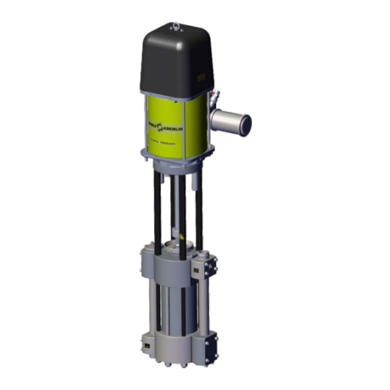
4 Available configurations Rexson parts number of High viscosity pumps Presentation of the pump REXSON 4B6000 A high flow pump with very low pulsation dedicated to paint circulation systems up to 54 liters per minute at 9 cycles/minute two different air motors to allow you to cover pressures from 10 to 30 bar. - Page 18 Available configurations 4.2 Table 1 Fluid section-Air motor selection Available motors Pressure Maximum air inlet Maximum outlet Documentation ratio pressure fluid pressure reference NONE MOTOR 7200 3 : 1 582144110 MOTOR 9200 5 : 1 582145110 R E X 6000 ...
- Page 19 Available configurations 4.4 Table 3 Seals pack selection Available seals packing Static seals "O"-rings Cup seals Piston seals packing packing UHMW PE PTFE + Leather EPDM PTFE and Leather UHMW PE PE + Leather PE and Leather UHMW PE R E X 6000 ...
-
Page 20: Identification
Identification 5 Identification 5.1 Description of the marking of the plate Principles This equipment complies with the following provisions: Machinery Directive (2006/42 / EC), Low Voltage Directive 2006/95 EEC EMV Directive 2004/108 EEC Safety of machinery - Basic terms, general implementation guidelines DIN EN ISO 12100 T1/T2 ... - Page 21 Identification Description SAMES KREMLIN Manufacturer's mark STAINS FRANCE POMPE / PUMP Pump reference and serial number. The first two digits indicate the year of manufacture. REF / SERIE PROD Maximum product pressure (Bar/Psi) MAX. PRES. (Bar/Psi) Maximum air pressure (Bar/Psi)
-
Page 22: Correspondence Table New Part Numbers / Significant Designations
Identification 5.2 Correspondence table New part numbers / Significant designations New part number Significant designation 66 MO 6000 M S F 000 REX4B6000-MO-MA-FO-SE Options Motor MOT7200 MOT9200 Material Stainless Steel Seal PE (FKM) PTFE + Leather (EPDM) PE + Leather (FKM) In / Out 2’’F BSPP M 52x200... -
Page 23: Correspondence Table Existant Part Numbers / Significant Designations
Identification 5.3 Correspondence table Existant part numbers / Significant designations Existant part Significant designation Motor Material Foot Seal number MOT7200 47 225 120 01 01 REX4B6000-72-SS-G4-01 3 : 1 Stainless Steels 2" BSPP PE (FKM) MOT7200 PTFE + 47 225 120 01 02 REX4B6000-72-SS-G4-02 3 : 1 Stainless Steels... -
Page 24: Technical Characteristics
Technical characteristics 6 Technical characteristics 6.1 General characteristics Ø Technical characteristics Volume per 6000 cm cycle 202.90 oz Ø Stroke 212 mm / 8.35 in Fluid outlet Selon les connection matériaux de construction Weight 115 kg / 254 lb Maximum fluid 80°C / 176°F temperature Wetted parts... -
Page 25: Wall Bracket (Accessory)
Technical characteristics (General characteristics - continued) Materials of construction Stainless steel Pump body Wet Cup Stainless steel Upper body Stainless steel Cylinder Stainless steel chromed Piston Stainless steel chromed Stainless steel Check Valve Ball Stainless steel Seat Stainless steel 6.2 Wall bracket (accessory) Dimensions... -
Page 26: Principle Of Operation
Technical characteristics 6.3 Principle of operation Expected use These pumps coupled to air or hydraulic motors are intended for transferring or spraying different liquid or pasty products with a desired flow rate and output pressure. Functional description When the piston (1) rises, check-valves 2 and 5 close, while check- valves 3 and 4 open. - Page 27 Technical characteristics ATTENTION! The friction generated by the movement of the product inside the pump and its accessories, as well as that caused by the seals, creates static electricity that can cause fire or explosion. Therefore, the fluid section system must be earthed via the motor ground cable (see the motor instruction manual for its ground connection).
-
Page 28: Installation
It is imperative to comply with an air motor/fluid section combination provided SAMES KREMLIN Make sure that all connections of the pump and fluid section components - cables, hoses and pipes - are installed in such a way that they do not cause people to fall. -
Page 29: Air Supply Connection
Installation 7.2.2 Air supply connection Ensure that inbound air supply and hose are of correct size to reduce pressure fluctuations and pressure drops. 7.3 Storage Pump Place the equipment away from moisture after closing the various air inlets and various openings (plugs). Storage before installation: ... -
Page 30: Commissioning
Commissioning 8 Commissioning The fluid sections are integrated in a system, if necessary refer to any additional instructions for further information on commissioning. Pump Pumps are tested for operation at the factory using a light weight oil lubricant. Before commissioning, this lubricant must be removed by flushing with a suitable solvent. -
Page 31: Use Of The Product
Use of the product 9 Use of the product 9.1 User settings Before commissioning, half fill the cup as well as the 2 tanks with lubricant "T". The cup nut must be tightened moderately. Overtightening quickly damages the gland packing. A wrench is supplied to allow proper tightening. -
Page 32: Safety In Production
Use of the product 9.2 Safety in production Guards (motor cover, coupling guard, housings, ...) are set up for safe use of the equipment. The manufacturer can not be held responsible in case of bodily injury as well as breakdowns and / or damage of the material resulting from the destruction, the occultation or the total or partial removal of the protectors. -
Page 33: Shutdown Procedure
Use of the product 9.4 Shutdown procedure Pump To avoid the risk of personal injury, material injections, injuries caused by moving parts or electric arcs, it is imperative that the following procedure be followed before any work is carried out when shutting down the system, assembling, cleaning or changing the nozzle. -
Page 34: Diagnostic Help / Troubleshooting Guide
Use of the product 9.5 Diagnostic help / Troubleshooting guide Possible symptoms of faults / Causes of faults / Remedies to apply Defaults Possible causes Remedies Tighten the cup. One lubricant gets colored Insufficient tightening of the and its level increases packing nut Incorrect assembly of seals Check the assembly. - Page 35 Use of the product Defaults Possible causes Remedies Pump cycles up and down One check Valve, head piston Replace parts. at different speeds seals or cylinder worn. Seals incorrectly mounted or Check mounting; change necessary. damaged The pump does not deliver Insufficient air pressure to the Check;...
-
Page 36: Maintenance
These procedures cover only the most common problems. If the information given here does not solve the problem you are experiencing, please contact your local SAMES KREMLIN representative for assistance. During prolonged shutdown, stop the pump when the piston is in the low position. -
Page 37: Preventive Maintenance Plan
Maintenance 10.1 Preventive maintenance plan ATTENTION Before pump maintenance service work performed, it is imperative to follow the depressurization procedure and the safety instructions. Routine maintenance after a certain number of operating hours is recommended. This is defined by the service department of the user and depends on the product, the working cycle and the usual pressure. - Page 38 Maintenance Yearly Remove the fluid section completely. Clean all the parts with the appropriate solvent cleaning. Install new seals during the assembly of the pump (refer to package of spare seals). Lubricate the piston and the inside of the cylinder to prevent from damaging the seals.
-
Page 39: General Preconisation Maintenance
Maintenance 10.2 General preconisation maintenance ATTENTION Before pump maintenance service work performed, it is imperative to follow the depressurization procedure and the safety instructions. Before each reassembly Clean the parts with the appropriate cleaning solvent. Fit new seals if necessary, after greasing them. ... -
Page 40: Disassembly / Reassembly Operation
Disassembly / Reassembly operation 11 Disassembly / Reassembly operation ATTENTION Before pump maintenance service work performed, it is imperative to follow the depressurization procedure and the safety instructions. ATTENTION The equipment is subject to the ATEX directive and must not be modified under any circumstances. Failure to comply with this recommendation does not engage our responsibility. - Page 41 Disassembly / Reassembly operation (For a full description of spare parts, see Part 12 - Spare Parts)
-
Page 42: Disassembly Of The Fluid Section
Disassembly / Reassembly operation Disassembly of the fluid section Place the pump in a vertical position, resting on the ground on the face of the connection plate (1), Unscrew the 16 screws (20) securing the inlet/outlet flanges / connection tube and those of the valve boxes (upper and lower), ... -
Page 43: Lower And Upper Valves
Disassembly / Reassembly operation Lower and upper valves Unscrew the 4 screws (7A), Take 2 screws (7A) and screw them into the threads of the plug (16) to remove the plug (16) from the upper body (23), Recover the ball housing (17), the ball (18), the seat (19) and the seals (8). -
Page 44: Reassembly Fluid Section
Disassembly / Reassembly operation Reassembly fluid section Place the upper block (23) on the tie-rods (5 and Place the cylinder (25) equipped with the seals (24), Fit the piston (lubricate the seal with neutral oil) into the cylinder, ... -
Page 45: Spare Parts
Spare parts 12 Spare parts Use only genuine SAMES KREMLIN accessories and spare parts designed to withstand the pump's operating pressures. - Page 46 Spare parts REX4B6000 - - - M 52x200 2’’ F BSPP Stainless Steel Spare part Ind. Description # Ref. level** Connection flange 209 498 St steel Tie-rod coupling 209 879 209 582 Tie-rod 209 497 Wet cup 210 126 Screw, model CHc M 8x20 88 904...
-
Page 47: Recommended Seals Pack
Spare parts REX4B6000 REX4B0570 - - - - - - 2’’ F BSPP M 52x200 Inox Spare part Ind. Description # Ref. level** Wrench 207 835 * Seal kit Depending upon choice - refer to table (Ind. 8, 10, 12, 22, 24, 27, 31) * Recommended maintenance parts. -
Page 48: Accessories
Spare parts Accessories Ind. Description # Ref. Bottle of lubricant T (125 ml / 0,034 oz) 149 990 020 Wall bracket 9 015 Ind 50... -
Page 49: Seals Pack Composition: 01 And 02
Spare parts Seals pack composition: 01 and 02 Seals pack: 106 365 106 366 Ind. Description Material Material O-Ring 84 052 84 414 EPDM Spacer 210 144 PEEK 210 144 PEEK Cup packing 209 658 PTFE 209 701 209 657 Leather O-Ring 84 288... -
Page 50: Seals Pack Composition: 03
Spare parts Seals pack composition: 03 Seals Pack: 106 367 Ind. Description Material O-Ring 84 052 Spacer 210 144 PEEK Cup packing 209 701 209 657 Leather O-Ring 84 288 O-Ring 84 380 O-Ring 80 027 Piston seal 209 476 ⇓...
Need help?
Do you have a question about the REXSON 4B6000 and is the answer not in the manual?
Questions and answers