Table of Contents
Advertisement
Quick Links
Service Manual for:
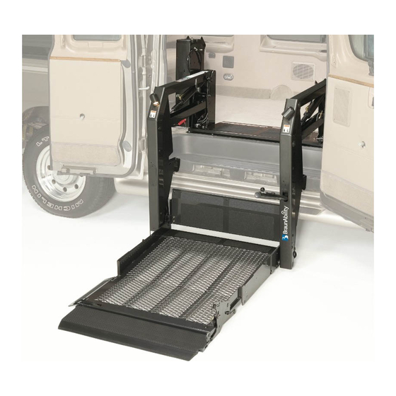
UVL855IRS
®
Under-Vehicle Lift
Commercial Wheelchair Lifts
Series
02
02
www.braunlift.com
®
www.braunability.com/international
ISO 9001:2008
631 West 11th Street, Winamac, IN 46996, USA
Phone: +1 574 946 6153
Fax: +1 574 946 4670
36579 Rev. B
March
Original Instructions
Original Instructions
2011
Advertisement
Table of Contents

Related Manuals for Braun Corporation Under-Vehicle Lift 2 Series


Summary of Contents for Braun Corporation Under-Vehicle Lift 2 Series
- Page 1 Service Manual for: UVL855IRS ® Under-Vehicle Lift Commercial Wheelchair Lifts Series www.braunlift.com ® www.braunability.com/international ISO 9001:2008 631 West 11th Street, Winamac, IN 46996, USA Phone: +1 574 946 6153 Fax: +1 574 946 4670 36579 Rev. B March Original Instructions Original Instructions 2011...
- Page 2 Congratulations We at The Braun Corporation wish to express our fullest appreciation on your new purchase. With you in mind, our skilled craftsmen have designed and assembled the finest lift available. This manual provides maintenance and service-related material. Braun UVL Series ™...
-
Page 3: Table Of Contents
Contents Service Safety Precautions .......... 2-3 ............. 4 Lift Terminology ............... 5 Switch and Sensor Locations .......... 6 Switch LED Diagnostics ..........7 Carriage Adjustments ............7 Floor Level and Bridge Plate Adjustments....8-11 Static and Dynamic Tests ......... 12-13 Maintenance and Lubrication ........ -
Page 4: Service Safety Precautions
Service Safety Precautions Safety Symbols SAFETY FIRST! Know That..The information contained CAUTION W ARNING in this manual and This symbol indicates This symbol indicates is provided for your use and important safety in- important information safety. Familiarity with proper formation regarding a regarding how to potentially hazardous... - Page 5 Lubrication Schedule contained in this manual. Disconnect the power cable at the battery prior to servicing. W ARNING Never modify (alter) a Braun Corporation lift. W ARNING W ARNING Never install screws or fasteners (other than factory equipped).
- Page 6 Lift Specifications manual. Any use of equipment other than instructed in this manual is prohibited. kg (2000 lb) load. Operating Temperature This equipment will operate in its intended ambient at a minimum between +5ºC and +40ºC. Relative Humidity Altitude This equipment will operate correctly up to 1000m above mean sea level. Sound Pressure Level Transportation and Storage Power Requirements...
-
Page 7: Lift Terminology
Lift Terminology Hand-Held Lift Mounting Pendant Brackets (6) Control Hydraulic Cylinders Bridge Plate Lift Housing Lifting LIFT 81812 Arms Roll Stop Hydraulic Cylinder W AR NI NG h T-ha uall y mov ndle lock befo e plat fully Fail resu driv form lt in... -
Page 8: Switch And Sensor Locations
Switch and Sensor Locations Lift Out Limit Switch 73950A Full Out Cam Full Out Lift Out Cam 73775 Limit Switch 73774 73950A Pressure Switch 73960A LIFT LIFT LIFT 81812 Push T-ha ually ndle lock Failu befo e platf enga fully resu lt in drivi... -
Page 9: Switch Led Diagnostics
Switch LED Diagnostics Floor Level Switch: Diagnostic LED “FL LVL” Lift Out Switch: The Lift Out Switch stops in- will be illuminated when the switch is contacting ward travel of the carriage/platform during Stow the cam. Detailed on page 8. function (activated by the housing-mounted Lift Out Cam). -
Page 10: Floor Level And Bridge Plate Adjustments
Floor Level and Bridge Plate Adjustments bottom of the platform must be CAUTION plate must rest solidly on vehicle 36514 Do not adjust bridge plate linkage rod. Linkage rod adjust- Ensure the lift is positioned and positioning of the platform and ment may result in lift bridge plate requires a combina- damage. - Page 11 Floor Level and Bridge Plate Adjustments Bridge Plate Cam Adjustment (de- Floor Level Requirements: When the lift is po- tailed in previous section). If the Floor Level Requirements (at right) are not met - adjust the Bridge Plate cam as the bridge plate must rest solidly on vehicle detailed in the following procedures.
- Page 12 Floor Level and Bridge Plate Adjustments Bridge Plate Cam Adjustment 4. Remove the cam securement nut 3.8 cm -6.4 cm (Figure D). Partially fold bridge plate " - (1 1/2 2 1/2" to take pressure off the cam and ease cam bolt removal.
- Page 13 Floor Level and Bridge Plate Adjustments Usable Platform Length Do not adjust CAUTION the bridge plate linkage rod Improper bridge unless plate linkage rod usable platform Linkage rod adjustment affects angle adjustment may length is need- of bridge plate (vertical position). result in lift damage.
-
Page 14: Static And Dynamic Tests
Static and Dynamic Tests Compatibility between the lift and the vehicle Static Test Deformation A load of 375kg is applied to the platform and subsequently removed. deformation has occurred in any part of the lift or its attachment to the vehicle which could affect the function of the lift. - Page 15 Static and Dynamic Tests Dynamic Test normal lifting and lowering. 1. Lower platform to the ground. 2. Place 300kg at center of platform. 3. Press up switch and verify that the lift is able to operate throughout its full range of normal lifting and lowering movements.
-
Page 16: Maintenance And Lubrication
Maintenance and Lubrication 36513 36514 components. Plat- W ARNING trouble-free lift operation. Inspecting the lift for form components Maintenance and should be a part of the transit agency daily service nants when lowered lubrication procedures program. Simple inspections can detect potential to the ground may must be performed as problems. - Page 17 Maintenance and Lubrication Lubrication Diagram Carriage Rollers (bearings) Drive Chain and Rollers Drive Chain Release Latch Hydraulic Eccentric Cylinder Spring Pivot Shaft Pivot Points Rollers Torque Points (bearings) Tube Rolling Pivot Points Carriage Arm Slot Area Lifting Arm LIFT 81812 Pivot Points Carriage Rollers...
- Page 18 Maintenance and Lubrication Roll stop and lower closure pivot Apply Light Oil - See Lubrication points (2) Diagram Inspect roll stop and lower closure for Correct or replace damaged parts. proper operation Inspect roll stop seal and lower closure gasket Roll Stop latch pivot point Apply Light Oil - See Lubrication Diagram...
- Page 19 Maintenance and Lubrication Carriage rollers (bearings) Apply Light Oil - See Lubrication Diagram Eccentric shaft rollers (bearings) Apply Light Oil - See Lubrication Diagram Apply Door-Ease - See Lubrication area Diagram. Apply to the surface area Hydraulic cylinder pivot points (4 per Apply Light Oil - See Lubrication cylinder) Diagram...
- Page 20 Maintenance and Lubrication securement hardware for wear or proper operation Inspect torque tube cams for 1500 Inspect housing cam brackets for Cycles or leaks Inspect power cable Inspect handrails for securement Hydraulic Fluid (Pump) - Check level. Notice: Fluid should be changed if there is visible contamination.
-
Page 21: Troubleshooting Diagnosis Chart
Troubleshooting Diagnosis Chart 36513 36514 An Electrical Schematic and Hy- If a problem occurs with your W ARNING draulic Diagram are provided to aid in troubleshooting. Troubleshooting and yourself. Contact your sales repair procedures representative. The cause of must be performed the problem can be determined ploded views and corresponding by locating the lift function and... - Page 22 Troubleshooting Diagnosis Chart FUNCTION POSSIBLE CAUSE REMEDY 3.00 PUMP DOES 3.11 Up Solenoid Check for power on pump “T” wire going to NOT RUN solenoid. WITH MANUAL 3.12 Bad power and ground See 1.00 OVERRIDE HAND-HELD PENDANT Check full out switch for proper operation/ad- 4.11 FULL OUT diagnostic LED justment.
- Page 23 Troubleshooting Diagnosis Chart FUNCTION POSSIBLE CAUSE REMEDY 8.11 Faulty Below Stow switch. Check for proper operation of Below Stow 8.00 BELOW STOW (BELOW) diag- switch. Replace or adjust switch as necessary. LIFT WILL NOT nostic LED not illuminated STOW WITH HAND-HELD 8.12 See 12.0 PENDANT...
- Page 24 Troubleshooting Diagnosis Chart 13.00 13.11 Faulty wiring Check for proper wiring to door openers. DOORS DO NOT OPEN CONTACT REMOVAL 1. Remove orange wedge using needle nose pliers or a hook removing the contact will displace shaped wire to pull wedge straight the same time releasing the lock the seal out.
-
Page 25: Lift Electrical Schematic
Page 23... -
Page 26: Hydraulics Parts List
Hydraulic Parts List Item Qty. Description Part No. Pump Assembly, UVL Power Pack - 24 Volt - Mod 87060-24V-MOD Motor, Pump 16504-IS Valve, “Down” (with Solenoid) 16505 Clamp, Reservoir - H-48 17069 Reservoir Replacement Kit (Includes Item #10) 88188K O-Ring (only), Hand Pump Mounting 17351 Hand Pump (Backup) with O-Rings (Includes Item #6) 87065... -
Page 27: Hydraulics Diagram
Hydraulics Diagram Arrow must face pump Arrow must face pump NOTICE Remove power from pump module and any spark source before working with hydraulic Use caution when working on components proper eye protection. Use inside pump module. Available energy of protective gloves for prolonged 1680 VA creates an energy hazard. -
Page 28: Pump Module Parts List
Pump Module Parts List Item Qty. Description Part No. Pump Assembly, UVL Power Pack - 24 Volt - Mod 87060-24V-MOD Adapter, 1/4" Male NPT x 7/16-20 Male JIC 37° 10130 Handle, Pump w/Bracket 17206W Screw, 1/4-20 x 3/8", Pan Head Phillips 82769 Clamp-Spring-Pump Handle 12350... -
Page 29: Pump Module Diagram
Page 27... -
Page 30: Repair Parts List
Repair Parts List - UVL855IRS Series 02 Item Qty. Description Part No. Item Qty. Description Part No. Tape, Double Face, 1/16" x 3/4" x 524" 82033R524 Housing Weldment 75101EVOMW-02 Clamp, Lift Mounting 73733 Lid, Upper Edge Seal 75746EVOM-02 Chain Release Assembly 73760EVOMA-02 Screw, 10-32 x 1/2"... -
Page 31: Housing Detail
Page 29... -
Page 32: Carriage Detail
Carriage Exploded View Detail - UVL855IRS Series 02 89 95 50 30 42 39 Page 30... -
Page 33: Platform Detail
Platform Exploded View Detail - UVL855IRS Series 02 Page 31... -
Page 34: Decals And Antiskid
Decals and Antiskid Notice: Clean surfaces with isopropyl alcohol before decal or W ARNING antiskid application. Use a clean cloth or paper towels. Do not use oily shop rags. Wipe surface free of residue with dry portion Replace missing, worn of cleaning cloth. - Page 35 Decals and Antiskid Part No. Description Inspect/ Made in America 18229 26551-F Oper UVL, Auto IB Manual HR-FR 27707-FR Lift Rating UVL 660LB (300KGS)-FR 29055-FR Lift Out Cam, UVL-FR Full Out Cam, UVL-FR 29058-FR Stow Start Cam, UVL-FR 29059-FR 29060-FR Floor Level Cam, UVL-FR 29061-FR Ground Pressure Sensor, UVL-FR...
- Page 36 Decals and Antiskid Inspect your lift for any missing or worn antiskid. Order as W ARNING needed. Notice: Clean surfaces with isopropyl alcohol before decal or antiskid application. Use a clean cloth or paper towels. Replace missing, worn Do not use oily shop rags. Wipe surface free of residue with dry or illegible decals.
- Page 37 à main, ouvrir la soupape de la pompe à main (tourner dans le sens anti-horaire). 2. Tirer le bouton rouge. FERMER N'ouvrir que d'un demi-tour seulement. 29487-FR Instructions, Pop Valve 29487-FR The Braun Corporation C AUTION 1-800-THE LIFT ® BRAUNLIFT.COM ® MODEL NUMBER AVERTISSEMENT XXXXXXXXXX...
- Page 38 Decals and Antiskid BK-2.08-14 36650 Electrical Components - Lift 36650 Manual Operation 36865-FR Fuse No. Voltage Amperage SC I/R Type Size F1 & F2 250 VDC 5 Ampere 200A @ 250VDC 1.25"L x 0.25"W x 0.25"H 32 VDC 3 Ampere 1000A @ 32VDC 0.75"L x 0.2"W x 0.488"H 36644...
- Page 39 Decals and Antiskid The Braun Corporation Authorized Representative UVL-Lift AB Åkerivägen 7 S-443 61 Stenkullen SWEDEN Telephone: +46-302 254 00 E-mail: contact@autoadapt.se Internet: www.autoadapt.se 36552 Authorized Representative 36552 RD-3.31-12 RD-3.31-12 36649 HAYON ELEVATEUR MONTEE Electrical Components - Module 36649 DESCENTE...
- Page 40 Decals and Antiskid Additional Decals Supplied in Lift Parts Box Decal, Outer Barrier Protect-UVL 42.375" x 3.625" 36434 AVERTISSEMENT Veillez à toujours vous trouver de dos au véhicule et à enclencher les freins du fauteuil avant d’actionner le hayon. 81814-F Caution Lock Brakes 81814-F AVERTISSEMENT...
-
Page 41: Declaration Of Conformity - Machinery
Hydraulic Lift System UVL855IRS Series 02 and Newer International Lifts Manufacturer: Braun Corporation 631 West 11 Street Winamac, IN 46996 Authorized Representative: Braun Corporation Authorized Representative UVL-Lift AB Åkerivägen 7 S-443 61 Stenkullen SWEDEN Telephone: +46-302 254 00 E-mail: contact@autoadapt.se Internet: www.autoadapt.se... - Page 42 ® Notes on Declared Standards referenced in the Declaration. BS EN 13857:2008 Safety of machinery. Safety distances to prevent hazard zones being reached by upper and lower limbs. BS EN ISO 13850:2008 Safety of machinery - Emergency stop - Principles for design.
-
Page 43: Declaration Of Noise Emission
® Declaration of Noise Emission The Braun Corporation UVL855IRS International Series System Sound Pressure Levels per EN ISO 11202 as based on testing on similar models are as follows: Idle Operating 68 dB (A) (Operator Position) 75 dB (A) LpAm... -
Page 44: Declaration Of Conformity - Emc
Hydraulic Lift System UVL855IRS Series 02 and Newer International Lifts Manufacturer: Braun Corporation 631 West 11 Street Winamac, IN 46996 Authorized Representative: Braun Corporation Authorized Representative UVL-Lift AB Åkerivägen 7 S-443 61 Stenkullen SWEDEN Telephone: +46-302 254 00 E-mail: contact@autoadapt.se Internet: www.autoadapt.se... - Page 45 "Providing Access to the World" ® Over 300 Braun Dealers Worldwide Dealers Worldwide ® "Providing Access to the World" International Corporate Hdqrs: P .O. Box 310 Winamac, IN 46996 USA ® 1-800-THE LIFT (574) 946-6153 FAX: (574) 946-4670...
- Page 46 All illustrations, descriptions and specifications in this manual are based on the latest product information available at the time of publication. The Braun Corporation reserves the right to make changes at any time without notice. at the time of publication. The Braun Corporation reserves the right to make changes at any time without notice.
Need help?
Do you have a question about the Under-Vehicle Lift 2 Series and is the answer not in the manual?
Questions and answers