Table of Contents
Advertisement
33220
"Providing Access to the World"
International Corporate Hdqrs: P.O. Box 310
1-800-THE LIFT
®
(574) 946-6153
Patent #5,261,779
Patent #5,261,779
Patent #5,261,779
Patent #5,261,779
Patent #6,065,924
Patent #6,065,924
34739
Patent #6,065,924
Patent #6,065,924
Patent #6,238,169
Patent #6,238,169
March
Patent #6,238,169
Patent #6,238,169
Patent #6,464,447
Patent #6,464,447
2008
Patent #6,464,447
Patent #6,464,447
Service Manual for:
Century
Public Use Wheelchair Lifts
Series
DOT — Public Use Lift
DOT — Public Use Lift
"DOT — Public Use Lift" verifies that this platform lift meets the
"public use lift" requirements of FMVSS No. 403. This lift may be
installed on all vehicles appropriate for the size and weight of the
lift, but must be installed on buses, school buses, and multi-
purpose passenger vehicles other than motor homes with a gross
vehicle weight rating (GVWR) that exceeds 4,536 kg (10,000 lb).
®
®
Winamac, IN 46996 USA
FAX: (574) 946-4670
Patent #6,599,079
Patent #6,599,079
Patent #6,599,079
Patent #6,599,079
Patent #6,692,217
Patent #6,692,217
Patent #6,692,217
Patent #6,692,217
Patent #6,739,824
Patent #6,739,824
Patent #6,739,824
Patent #6,739,824
Patents Pending
Patents Pending
Patents Pending
Patents Pending
2
2
BA
BA
W ARNING
Read manual
before installing
or servicing lift.
Failure to do so
may result in
serious bodily
injury and/or
property damage.
Advertisement
Table of Contents

Related Manuals for Braun Corporation Century 2 Series


Summary of Contents for Braun Corporation Century 2 Series
- Page 1 Service Manual for: Century Public Use Wheelchair Lifts Series DOT — Public Use Lift DOT — Public Use Lift “DOT — Public Use Lift” verifies that this platform lift meets the “public use lift” requirements of FMVSS No. 403. This lift may be installed on all vehicles appropriate for the size and weight of the lift, but must be installed on buses, school buses, and multi- purpose passenger vehicles other than motor homes with a gross...
- Page 2 Congratulations We at The Braun Corporation wish to express our fullest appreciation on your new purchase. With you in mind, our skilled craftsmen have designed and assembled the finest lift available. This manual provides service-related material. Refer to the FMVSS No. 403 Quick Reference Installation Sheet for installation instructions, operating instructions and maintenance procedures.
-
Page 3: Table Of Contents
Contents Troubleshooting and Maintenance Lift Terminology............. 2 Switch and Sensor Locations ........3 Certification Checklist Diagnostic Procedures ..4 Platform Fold Pressure Adjustment ......5 Platform Angle Adjustment ........6-7 Platform Stop Blocks ........... 7 Tower Microswitch Adjustment ........8 Lubrication Diagram ............ -
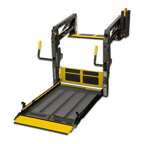
Page 4: Lift Terminology
Lift Terminology Towers (2) Top Parallel Arms (2) Pump Module (Rear) Main Cylinders (2) Visual Threshold Audible Warning Threshold Adjustable Quiet-Ride Stow Blocks (2) Hand-Held Warning Pendant (not visible) Control Unfold Assist Compression Springs (2) Lift-Tite ™ Latches (2) Platform Lights (2) Vertical Arm Covers (4) Threshold Handrails (2) -
Page 5: Switch And Sensor Locations
Switch and Sensor Locations *Threshold Alarm & Partial Fold Microswitch Assy. *Threshold Alarm 975-3121A Threshold Strip Switch *Partial Fold Microswitch 33337A (2 strips per) Microswitch *Up & Unfold Right Inboard Microswitch Assy. 975-3121A *Up Microswitch Left Outboard *Unfold Microswitch Stow Interlock Microswitch IB Occupied Microswitch... -
Page 6: Certification Checklist Diagnostic Procedures
The following operations and conditions must be functionally verified in order for the lift to be FMVSS 403/404 compliant. If an operation does not function as described or a condition is not met, follow the refer- enced procedures to correct the problem or contact a Braun Corporation Product Support representative at 1-800-THE LIFT ®... -
Page 7: Platform Fold Pressure Adjustment
Platform Fold Pressure Adjustment 1. Position the platform at the floor level loading position. 2. Loosen the hex nut on the adjustment screw (do not remove hex nut). 3. Turn the adjustment screw counter clockwise until the platform does not fold when the Fold button is pressed. -
Page 8: Platform Angle Adjustment
Platform Angle Adjustment Adjusting the platform angle based on the Millennium “NL” Series relationship of the platform at ground level directly affects the angle of the platform Figure C when positioned at floor level. Unfold the lift and visually examine the angle of the platform when positioned at Angle A floor level. -
Page 9: Platform Stop Blocks
Platform Angle Adjustment Adjustment Allen screws are To raise the outboard end Note: Both adjustment screws provided on each side of the lift of platform - turn adjustment must be adjusted equally. platform for adjusting the platform screw clockwise. angle. Adjust platform angle as Apply Loctite ®... -
Page 10: Tower Microswitch Adjustment
Tower Microswitch Adjustment TOWER TOWER TOWER TOWER 32943 32942 Figure E TOWER TOWER TOWER TOWER 32943 32942 Note: Left (rear) pump lift de- Note: Review adjustment picted. Right (front) pump procedures below and adjust lift is a mirrored image. as needed only. Tower 1 (Unfold) Switch Adjustment Tower 3 (Alarm) Switch Adjustment Floor Position from Stow... -
Page 11: Lubrication Diagram
Maintenance and Lubrication Lubrication Diagram ™ Lift-Tite Latch Dampening Spring Parallel Arm (2 springs - 4 Points) LO Pivot Pin Bearings (16) Hydraulic Cylinder Pivot Bushings (8) LO ™ Lift-Tite Latches Saddle (Tower Pivot Points - 2) Bearing (2) Parallel Arm Pivot Pin Bearings (16) Handrail Pivot Pin Bearings (4) -
Page 12: Maintenance And Lubrication Schedule
Product Support representatives will direct you procedures. Specified lubricants are available from to an authorized service technician who will inspect your The Braun Corporation (part numbers provided on lift. previous page). Outer barrier pivot points (2) - Page 13 Maintenance and Lubrication Schedule continued Inspect outer barrier latch for proper operation, Correct or replace damaged parts and/or relubri- cate. See Lubrication Diagram positive securement, and detached or missing spring(s) Cycles Inspect lift for wear, damage or any abnormal Correct as needed. condition Correct as needed.
- Page 14 Maintenance and Lubrication Schedule continued Inspect external snap rings: Resecure or replace if needed. • Outer fold arms (6) • Lift-Tite ™ latch rollers (2) • Lift-Tite ™ latch gas (dampening) springs (4) • Outer barrier latch gas springs (2) •...
- Page 15 Maintenance and Lubrication Schedule continued Inspect power cable Resecure, repair or replace if needed. Mounting Check to see that the lift is securely anchored to 4500 the vehicle and there are no loose bolts, broken Cycles welds, or stress fractures. Decals and Antiskid Replace decals if worn, missing or illegible.
-
Page 16: Notes
NOTES This page intentionally left blank. Page 14... -
Page 17: Lift Electrical Schematic
Lift Electrical Schematic RD(18) IB RAISED PLATFORM LIGHTS (OPTION) DESCRIPTION SYMBOL SWITCH BK(18) BK(18) RD(18) GN(20) CAPACITOR BK(22) BK(20) BK(18) BK(18) RD(18) RD(22) VT(20) MICROSWITCH LIFT BK(18) RD(18) GN(20) BK(18) BK(18) SWITCH BOX RD(18) LIGHT RELAY OUTER BARRIER DIODE OCCUPIED / RAISED BK(18) RD(18) OR(20) -
Page 18: Lift Wiring Diagram
Lift Wiring Diagram Light Relay Platform Lights (Option) RD(18) Counter 4-COND WIRE CODE 4-COND WIRE CODE COLOR COLOR BLACK(18) BLACK(18) BLUE(18) RED(18) WHITE(18) WHITE(18) GN(18) NOT USED NOT USED GN(20) GN(18) SILVER(22) GN(20) WH(18) SILVER(22) 6-COND WIRE CODE 6-COND WIRE CODE COLOR COLOR 1 2 3... -
Page 19: Hydraulic Schematic
Hydraulic Schematic Orifice Orifice Lifting Down Secondary Relief Valve Valve Valve 2500 Folding Relief Valve 1900 Opposite Pump Side Pump Cylinder BACKUP Cylinder PUMP PUMP Description Symbol Description Symbol Fixed Displacement Hydraulic Port Pump 2 Way 2 Position Pump Motor Solenoid Valve Pressure Compensated Backup Pump... -
Page 20: Hydraulics Parts List
Hydraulics Parts List Item Qty. Description Part # Pump Assembly (M-268-0114) 120G / 12V / Dual Relief 32858-12V Solenoid, 4-Post - Trombetta (Flat Mount) 31374 Motor, Pump - 12 Volt - Low RPM 29690 Valve Assembly, “Dual Relief" (complete) 31120K Cartridge (only), “Dual Relief"... -
Page 21: Hydraulics Diagram
Hydraulics Diagram Hydraulic Repair For repair of a hydraulic hose or cylinder, read this. Service Bulletin 27049 Hydraulic Pump Motor Manual Backup Pump Page 19... -
Page 22: Pump Module
(items 23 and 24) if a blue nylon patch is not present on the bolts when retrofitting an M268-0114 pump assembly. Loctite ® is available from The Braun Corporation under part number 11522-1. t Indicates items available for replacement part purposes only. These items are not included with replacement pump modules. -
Page 23: Pump Module Diagram
23 and 24) if a blue nylon patch is not present on the bolts when retrofitting an M268 pump assembly. Loctite ® available from The Braun Corporation under part number 11522-1. Note: Rear pump module shown, front pump module mirror image. -
Page 24: Ncl917Ib-2 Base Plate Assembly
Exploded Views and Parts Lists NCL917IB-2 Base Plate Assembly DWG. NOTES 1) LOOP TAPESWITCH WIRE BACK AND SECURE WITH WIRE TIE 4X. 2) TRIM AND TUCK WIRE TIE CLASP INTO HOLE 4X. "A" 14993 RIV-POP-SD66BS-3/16"-.25/.38/AUTO-BK 29765 CLAMP-INSULATED-1 3/8" NOTE: 10091 CABLE TIE-11"... -
Page 25: Ncl917Fib-2 Base Plate Assembly
Exploded Views and Parts Lists NCL917FIB-2 Base Plate Assembly DWG. NOTES 1) LOOP TAPESWITCH WIRE BACK AND SECURE WITH WIRE TIE 4X. 2) TRIM AND TUCK WIRE TIE CLASP INTO HOLE 4X. "A" 14993 RIV-POP-SD66BS-3/16"-.25/.38/AUTO-BK 29765 CLAMP-INSULATED-1 3/8" 10091 CABLE TIE-11" SOLID 31816 BOLT-SHOULDER, 5/16 X 5/8-1/4-20 SS W/PC 29729... -
Page 26: Ncl919Ib-2 Base Plate Assembly
Exploded Views and Parts Lists NCL919IB-2 Base Plate Assembly DWG. NOTES 1) LOOP TAPESWITCH WIRE BACK AND SECURE WITH WIRE TIE 4X. 2) TRIM AND TUCK WIRE TIE CLASP INTO HOLE 4X. "A" 14993 RIV-POP-SD66BS-3/16"-.25/.38/AUTO-BK 29765 CLAMP-INSULATED-1 3/8" 10091 CABLE TIE-11" SOLID 31816 BOLT-SHOULDER, 5/16 X 5/8-1/4-20 SS W/PC 29729... -
Page 27: Ncl919Fib-2 Base Plate Assembly
Exploded Views and Parts Lists NCL919FIB-2 Base Plate Assembly DWG. NOTES 1) LOOP TAPESWITCH WIRE BACK AND SECURE WITH WIRE TIE 4X. 2) TRIM AND TUCK WIRE TIE CLASP INTO HOLE 4X. "A" 14993 RIV-POP-SD66BS-3/16"-.25/.38/AUTO-BK 29765 CLAMP-INSULATED-1 3/8" 10091 CABLE TIE-11" SOLID 31816 BOLT-SHOULDER, 5/16 X 5/8-1/4-20 SS W/PC 29729... -
Page 28: Top Parallel Arm Assembly
Exploded Views and Parts Lists Top Parallel Arm Assembly - Front 10058 NUT-5/16-18 HEX/AUTO-BK 10068 WASHER-5/16" LOCK/AUTO-BK 15858BK BOLT-CARR 5/16-18 X 3/4/AUTO-BK 16368 WASHER-5/16" EXTERNAL TOOTH 24440 BOLT-5/16-18 X 3/4-BHSC/AUTO-BK 28593A ASSY-BLOCK-GUIDE-PLATFORM-STOW 955-2392CLXT BKT.-QUIET-RIDE MTG.-955 14993 RIV-POP-SD66BS-3/16"-.25/.38/AUTO-BK 915-0703 BRACKET-INNER SIDE PANEL GUIDE 11513 RIV-POP-SD64BS-3/16"-.13/.25/AUTO-BK 996-0449... -
Page 29: Bottom Parallel Arm Assembly
Exploded Views and Parts Lists Bottom Parallel Arm Assembly - Rear DWG. NOTES 1) ASSEMBLE SENSOR WITH FLAT SIDE AWAY FROM PARALLEL ARM. 18349 NUT-#10-32 W/LOCKWASHER/AUTO-BK 32514NA ASSY-IB OCCUPIED 31771 SHIM WASHER-.906"ID X 1.156"OD/.03"T/SS 24011 BEARING-FLANGE-3/4" X 3/8"-12FDU06 945-0458NKS ARM-PARALLEL/BOTTOM-FRONT (INCL. ITEMS 2-3) ITEM QTY. -
Page 30: Hydraulic Cylinder Assembly - Main
Exploded Views and Parts Lists Hydraulic Cylinder Assembly - Main RETRACTED 29.146 STROKE 14.625 EXTENDED 43.771 30° ±10° 15150 ELBOW-1/4 NPT 90° 1/4 BARB 26667 ELBOW-7/16-20 M/O-RNG/37*/.035 ORFICE C1514.3-0408N CYLINDER-14.625"/29.146 RETRACTED ITEM QTY. PART NO. DESCRIPTION Page 28... -
Page 31: Vertical Arm Assembly
Exploded Views and Parts Lists Vertical Arm Assembly - Rear DWG. NOTES NOTE: 1 1) INSERT SOCKET OF LIGHT ASSY THRU TOP KEY WHILE INSTALLING LIGHT. TIGHTEN SCREWS. 2) APPLY GREASE TO PIN PRIOR TO INSTALLING ROLLER. 3) HARNESS TO BE TUCKED INSIDE CHANNEL 4) BUSHING NOT SHOWN NOTE: 3 NOTE: 4... -
Page 32: Handrail Assembly
Exploded Views and Parts Lists Front Handrail Assembly * INDICATES ITEMS NOT SHOWN * 32519A SWITCH ASSEMBLY 29185 BALL STUD-13MM W/ 3/8-16 FEMALE THREAD GAS SPRING-14.468 EXT/8.956 COM-P1=1150N 29186 30227 WASHER-UHMW 0.75 OD X 0.39 ID X 0.25 13617 NUT-3/8-16 UNC HEX LOCK/AUTO-BK 945-0640RNA ASSY-FOLD ARM-48 FTG-REAR 11513... -
Page 33: Ncl917Ib-2 & Ncl917Fib-2 Platform Assembly
Exploded Views and Parts Lists NCL917IB-2 & NCL917FIB-2 Platform Assembly DWG. NOTES 1) USE LOCTITE 271 (B.C. #11522-1) ON SCREWS (B.C. #24537) 2) USE LOCTITE 290 (B.C. #29255) ON CLEVIS PINS (B.C. #24932BK). NOTE: NOTE: * ITEMS NOT SHOWN 10013 BOLT-5/16-18 X 1"... -
Page 34: Ncl919Ib-2 & Ncl919Fib-2 Platform Assembly
Exploded Views and Parts Lists NCL919IB-2 & NCL919FIB-2 Platform Assembly DWG. NOTES 1) USE LOCTITE 271 (B.C. #11522-1) ON SCREWS (B.C. #24537) 2) USE LOCTITE 290 (B.C. #29255) ON CLEVIS PINS (B.C. #24932BK). NOTE: NOTE: * ITEMS NOT SHOWN 10013 BOLT-5/16-18 X 1"... - Page 35 "Providing Access to the World" ® Over 300 Braun Dealers Worldwide ® "Providing Access to the World" International Corporate Hdqrs: P .O. Box 310 Winamac, IN 46996 USA 1-800-THE LIFT ® (574) 946-6153 FAX: (574) 946-4670...
- Page 36 All illustrations, descriptions and specifications in this manual are based on the latest product information available at the time of publication. The Braun Corporation reserves the right to make changes at any time without notice. time of publication. The Braun Corporation reserves the right to make changes at any time without notice.
Need help?
Do you have a question about the Century 2 Series and is the answer not in the manual?
Questions and answers