Table of Contents
Advertisement
�������
���������� ������ �� ��� ������
������������� ��������� ������ � ��� ��� ���
��������� ����
����� ��������
������ ����������
������ ����������
�����
������ ����������
������ ����������
������ ����������
������ ����
������ ����������
�������������������� ������ ����
������� ������
���������� ���������� �����
��������� �������
��������� �������
�
���
��������
�
���
��������
���
������� �����
������� �����
����� ������ ���� ������
��� ������ �����
��� �������� ���
������������ ������������
�
�
�������� �� ����� ���
���� ����� ��������
������ ����������
������ ����������
������ ����������
������ ����������
������� �������
������� �������
��
�
���
���������
�
���
���������
W ARNING
Read manual
before installing
or servicing lift.
Failure to do so
may result in
serious bodily
injury and/or
property damage.
���
���
��������� ����
��������� ����
��������� ����
��������� ����
������������ ���
������������ ���
Advertisement
Table of Contents

Related Manuals for Braun Corporation Century Series


Summary of Contents for Braun Corporation Century Series
- Page 1 �������������������� ������ ���� ������� ������� ������ �� ���������� ���������� ����� ��������� ������� ��������� ������� � ��� � ��� �������� ��������� � ��� � ��� �������� ��������� ��� ������� ����� ������� ����� ����� ������ ���� ������ ��� ������ ����� W ARNING ���...
- Page 2 This manual includes safety precautions, installation instructions, maintenance instructions and instructions for troubleshooting, if needed. Braun Century Series™ lifts are built for dependability and will provide years of pleasure and independence as long as the lift is installed and serviced as specified by a Braun certified technician, and the lift is operated by an instructed person.
- Page 3 Series 01 or Series 02 lift model. If you latest product information available at the are installing or servicing a Series 03 lift model, time of publication. The Braun Corporation read this supplement as well as all informa- reserves the right to make changes at any time without notice.
- Page 4 ™ Century Series CL917IB Supplement 30304 Series 03 CL917IB Floor Level Guideline Adjustments Unfold/Down and Up/Fold Microswitches: The Series 03 CL917IB Series 03 CL917IB features a new Unfold/Down Unfold/Down and Up/Fold and Up/Fold microswitch assembly. The Microswitch Assembly 975-3121A microswitch assembly is located in the pump side tower (shown below).
- Page 5 ™ Century Series CL917IB Supplement 30304 Series 03 CL917IB Wiring Diagram Note: Shown with lift in stowed position. Switch Box (As Viewed From Terminal Side of Switch) 9-COND WIRE CODE Power / Interlock COLOR BLACK - 6 COND. YELLOW - 6 COND. BROWN - 6 COND.
- Page 6 (items 41 and 42) if a blue nylon patch is not present on the bolts when retrofitting a pump assembly. Loctite ® is available from The Braun Corporation under part number 11522. Page 4...
- Page 7 ™ Century Series CL917IB Supplement 30304 Series 03 CL917IB Pump Module Diagram Pump Mounting Bolts Apply red #271 Thread ® Locker Loctite to the three pump mounting bolts (items 41 and 42) if a blue nylon patch is not present on the bolts when retrofitting a pump assembly.
- Page 8 Century Series CL917IB Supplement 30304 ™ Revised: 7-6-10 Series 03 CL917IB Repair Parts List Part Numbers of Items Dedicated per Lift Model Item Qty. Description CL917IB CL917FIB CL919IB CL919FIB Base Weldment 917R8148W33 917F8148W33 919R8148W34 919F8148W34 Plate, Pump Backing 975R0501 975F0501 975R0501 975F0501 Cover, Pump, 2-Piece, Back-Bottom...
- Page 9 ™ Century Series CL917IB Supplement 30304 Series CL917IB Lift Exploded View Revised: 2-9-04 Note: Illustrations depict components as equipped when specified lift series was in production. Replacement components may reflect newer lift series configurations. Page 7 Series 03 CL917IB Supplement 30304 Page 7...
- Page 10 ™ Century Series CL917IB Supplement 30304...
- Page 11 02 lift models Note: All illustrations depict Series 02 CL917IB plicable for CL917IB Century Series ™ are provided. lift models as equipped at the time of publication. Replacement components may reflect newer lift The Braun Serial No./Series No.
- Page 12 ™ Century Series CL917IB Supplement 30067 Series 02 CL917IB Electrical Schematic Note: Shown with lift in stowed position. DRAWING SHOWN WITH DESCRIPTION SYMBOL LIFT IN STOWED POSITION BATTERY NOTE: ALL NON-CIRCUIT BOARD CHASSIS GROUND MOUNTED WIRES ARE 20 GA. UNLESS OTHERWISE NOTED. CIRCUIT BREAKER LIFT SWITCH BOX...
- Page 13 ™ Century Series CL917IB Supplement 30067 Series 02 CL917IB Wiring Diagram Note: Shown with lift in stowed position. Switch Box (As Viewed From Terminal Side of Switch) 9-COND WIRE CODE Power / Interlock COLOR BLACK - 6 COND. YELLOW - 6 COND. BROWN - 6 COND.
- Page 14 ™ Century Series CL917IB Supplement 30067 Series 02 CL917IB Lift Interlock Installation The CL917 can be configured for use with a cus- tive logic mode. Below are the instructions for tomer supplied remote interlock with either a +12V proper negative logic (grounded) interlock installa- signal (positive logic) or a ground signal (negative tion.
- Page 15 ™ Century Series CL917IB Supplement 30067 Series 02 CL917IB Lift Interlock Installation The CL917 can be configured for use with a cus- tive logic mode. To convert to a positive logic tomer supplied remote interlock with either a +12V interlock mode, follow the instructions below. See signal (positive logic) or a ground signal (negative supplement page 4 for negative logic mode hookup.
- Page 16 (items 41 and 42) if a blue nylon patch is not ® present on the bolts when retrofitting a pump assembly. Loctite is available from The Braun Corporation under part number 11522. Page 6...
- Page 17 ™ Century Series CL917IB Supplement 30067 Series 02 CL917IB Pump Module Diagram Pump Mounting Bolts Apply red #271 Thread ® Locker Loctite to the three pump mounting bolts (items 41 and 42) if a blue nylon patch is not present on the bolts when retrofitting a pump assembly.
- Page 18 Century Series CL917IB Supplement 30067 ™ Revised: 7-6-10 Series 02 CL917IB Repair Parts List Part Numbers of Items Dedicated per Lift Model Item Qty. Description CL917IB CL917FIB CL919IB CL919FIB Base Weldment 917R7148W33 917F7148W33 919R7148W34 919F7148W34 Plate, Pump Backing 975R0501 975F0501 975R0501 975F0501 Cover, Pump, 2-Piece, Back-Bottom...
- Page 19 ™ Century Series CL917IB Supplement 30067 Series CL917IB Lift Exploded View Revised: 2-9-04 Note: Illustrations depict components as equipped when specified lift series was in production. Replacement components may reflect newer lift series configurations. Page 9 Series 02 CL917IB Supplement 30067 Page 9...
- Page 20 ™ Century Series CL917IB Supplement 30067...
-
Page 21: Table Of Contents
Contents Lift Terminology Systems Descriptions Lift Terminology Illustration ..........2 General Operation ............39 Introduction ..............3 Electrical ..............39-41 Direction ................3 Microswitches ............41 Lift Components .............. 3 Hydraulics ..............42-45 Lift Installation Troubleshooting Installation/Service Safety Precautions ....4, 5 Troubleshooting Diagnosis Chart ...... - Page 22 Lift Terminology A left side (rear) pump-equipped mirrored image of left side (rear) terminology, direction and lift lift model is depicted in the pump models (pump module components are provided on illustration below. Right side located on opposite end of base page 3.
-
Page 23: Lift Terminology
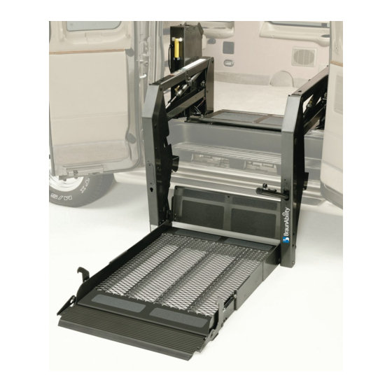
Lift Terminology Introduction Lift Components Outboard Roll Stop: The spring- loaded automatic outboard roll Braun CL917 Century Series lifts Pump Module: The lift- stop provides a ramp for wheel- are ADA compliant and commer- mounted pump module consists chair loading and unloading at... -
Page 24: Installation/Service Safety Precautions
Installation/Service Safety Precautions Safety Symbols SAFETY FIRST! Know That..The information contained CAUTION W ARNING in this manual and supple- ments (if included), is provided This symbol indicates This symbol indicates for your use and safety. Familiar- important safety important information ity with proper installation, information regarding regarding how to... - Page 25 Disconnect the power cable at the battery prior to servicing. W ARNING Keep hands, arms and all other body parts clear of moving parts. W ARNING Never modify (alter) a Braun Corporation lift. W ARNING Replacement parts must be Braun authorized replacements. W ARNING Never install screws or fasteners (other than factory equipped).
-
Page 26: Pre-Installation Notes
Stepwell Installations: When and any obstruction on the installing a CL917 model lift in vehicle floor (such as a rubber Braun CL917 Century Series lifts the side cargo door (with sill or threshold). must be installed and serviced by stepwell), it is not permissible... - Page 27 Pre-Installation Notes Lift Installation Checklist Read this information before Two ground cables are provided. removing the clear plastic One ground cable is connected to A generic Lift Installation shipping wrap and/or placing the pump. The second ground Checklist is provided as a final the lift in the vehicle.
-
Page 28: Lift Installation Instructions
Lift Installation Instructions Installation Parts Please check the Installation Parts List and Tools List to see that you have everything needed to begin. Report any missing items. Item Qty. Description Part No. Installation Parts Package (complete) Includes all following items 29821A Bracket, Underfloor, Reinforcement 25915-04... - Page 29 Lift Installation Instructions Figure A Ford Rear Door Installation: Four underfloor Position star washers and underfloor reinforcement mounting hardware as specified (per brackets must chassis and floor configuration). be used. Details on page 15. Through Floor Only: Position star washer Star Washers between floor and 2-1/2"...
-
Page 30: Lift Positioning
Lift Installation Instructions Note: Read all Pre- Lift Positioning Installation Notes prior to installation. The lift towers (upright supports) and the vertical arms must be parallel (aligned) with the vertical sides of the door jamb and should be perpendicular (90˚) to the vehicle floor. W ARNING Install lift and power platform to fully... - Page 31 Lift Installation Instructions Clearance: Visually center the unit in the opening. Position the base plate parallel to (aligned with) the vehicle lift door sill or stepwell as shown in Figure D. Close the Lift must clear vehicle door(s). From inside, door-mounted position the unit as close to the control box.
- Page 32 Lift Installation Instructions Lift Positioning (continued) Rear Door and Extensive Floor-to-Ground Installations: Figure G Position the lift in the rear door Rear Door and opening as outlined on page 1/2" Extensive 10. Depending on the particu- Minimum Floor-to-Ground lar lift model installed and the Clearance Installations particular vehicle configuration,...
-
Page 33: Lift Securement
Lift Installation Instructions Lift Securement Base Plate Mounting Optimum Bolt Locations There must be a total of eight Mounting Mounting Figure I 3/8"-16 x 4" carriage bolts (or 8" Bolts Bolts bolts) securing the base plate Inboard through the floor. Two 3/8"-16 x 8"... - Page 34 Lift Installation Instructions Lift Securement (continued) Underfloor Reinforcement Brackets (continued) Two base plate mounting bolts must secure Technical Assistance: If the reinforcement brack- each bracket. ets will not work as detailed for your particular installation, call 1-800-THE LIFT for technical Underfloor reinforcement brackets must reach assistance.
- Page 35 Lift Installation Instructions External Tooth Star Washers Eight 3/8" external tooth star washers are supplied Through Chassis: When securing base plate with each lift. Position star washers as follows. mounting bolts through chassis subframe members, position a star washer between the chassis and the Through Floor Only: When base plate mounting 3/8"...
- Page 36 Lift Installation Instructions Lift Securement (continued) Bolt Tightening Mounting Bolt Torque Speci- Tightening of the base plate alignment of towers and vertical mounting bolts directly affects arms while tightening. See Figure fications: 28 to 31 foot pounds. Adjustment to mount- vertical arm alignment and base M.
- Page 37 Lift Installation Instructions Power Cable and Ground Cable Installation CL917 pump modules feature a pump-mounted CAUTION ground cable and an external stud for connection of the lift power cable. A 1" I.D. plastic grommet is Position and secure provided for the power cable and ground cable ground cable clear access hole.
-
Page 38: Power Cable And Ground Cable
Lift Installation Instructions Power Cable and Ground Cable Installation (continued) Lift Ground Secure all cables using cable ties and/or cable clips (mount Two ground cables are provided. clips with self-tap screws). One ground cable is pump mounted (shown in photo on Cable page 17). - Page 39 Lift Installation Instructions Ground Cables: The pump Power Cable: Route, cut to length and connect the power cable before ground cable and battery-to- frame ground cable must be securing the cable to the vehicle. mounted to a common Connect battery-to-frame ground vehicle framing member to cable to negative (-) battery post.
- Page 40 Lift Installation Instructions Circuit Sentry Installation and Power Connection Offset Mount Bracket 28498 Figure P Flush Mount Bracket 28755 Circuit Breaker Top Post Mount Positive (+) 12 Volt Battery Post Side Post Mount 3/8-16 x 1" Hex Bolt Spacer Note: Compact Circuit Sentry Circuit Sentry Kit 29789KS Kit 29789KS is currently Item Qty.
- Page 41 Lift Installation Instructions Circuit Sentry Kit 29789KS is mounting surface and other W ARNING supplied to provide greater variables. Mounting brackets can installation versatility (less space be oriented as needed. required). Two types of mount- ing brackets are supplied (shown The Circuit Sentry must be in Figure P).
-
Page 42: Installation
Lift Installation Instructions Control Box and Harness Installation Groove Guide Quick-Disconnect Harness: “Quick-disconnect” hand-held controls are available with three types of cable (standard, armored and coiled). CL917 Series lifts are shipped without the control box harness installed. All harnesses are equipped with the same quick-disconnect sockets. - Page 43 Lift Installation Instructions Control Box Mounting: The control box mounts to storage clip bracket to the door as shown in Figure the inside face of the lift cargo door as shown in the Q on page 22. Insert control box storage clip in center photo below.
-
Page 44: Design Lifting Capacity
Lift Installation Instructions Design Lifting Capacity Century Series lifts are rated at a ration must support the lift and Positioning and Clearance design lifting capacity of 800 the lift load. Checklist and corresponding pounds. The combination of lift illustrations. Note: Refer to the... - Page 45 Lift Installation Instructions ✓ Positioning and Clearance Checklist Figure R Alignment: "Side" to "Side" Alignment: As viewed from outside the vehicle, the lift vertical arms and platform (when stowed) should be perpendicular (90°) to the vehicle floor and parallel (aligned) with the sides of door jamb (see points 8 and 9).
-
Page 46: Base Plate Plugs
Lift Installation Instructions Platform Angle Adjustment and Floor Level Adjustments The platform angle and floor W ARNING level positioning of the bridge plate (inboard roll stop) must be Adjust platform properly adjusted before angle and bridge operating the lift with a pas- plate floor level senger. -
Page 47: Passenger's Seat
Lift Installation Instructions Passenger's Seat (Vans) Reinstall passenger's seat in suitable location using the original (OEM) mounting hardware if previously removed. Torque seat mounting hard- ware per manufacturer's specifications. Owner's Manual Be certain the lift owner's W ARNING (operator's) manual is in the lift mounted manual storage pouch. -
Page 48: Platform Angle Adjustment Instructions
Platform Angle Adjustment Instructions W ARNING Outboard end of platform Adjust platform angle must contact as detailed here. ground first. Failure to do so may result in serious bodily injury and/or property damage. Wrong Adjusting the platform angle based on the relationship of the platform at ground level Wedges directly affects the angle of the platform when... - Page 49 Platform Angle Adjustment Instructions Adjustment Allen screws are provided on each side end of the platform. Note: Both adjustment screws of the lift platform for adjusting the platform angle. must be adjusted equally. Adjust platform angle as needed. See Figure U on previous page. Apply Turn the adjustment screw clockwise to raise the ®...
-
Page 50: Floor Level Guideline Adjustments
Floor Level Guideline Adjustments Wrong Must make full contact. Gap not permitted. Stop Block Guideline Stop blocks must make full contact with the edge of the vertical arms. Stop Block Vertical Arm Unfold/Down and Up/Fold Microswitches: The Floor Level Guideline Adjustments: The Unfold/Down and Up/Fold microswitches (limit Unfold/Down and Up/Fold microswitches control switches) are located in the pump side tower. - Page 51 Floor Level Guideline Adjustments Wrong Bump W ARNING Improper microswitch adjustment may result in serious bodily injury and/or Platform property damage. too high. When adjusting microswitches, stop block positioning and bridge plate positioning must be viewed. A combination of adjustments may be required to achieve a proper balance.
-
Page 52: Quiet-Ride Adjustment Instructions
Quiet-Ride Adjustment Instructions Adjustable Quiet-Ride Guided Stop Blocks and fixed installation procedures can result in potential rattles rubber bumpers mounted at key locations aid in also. If lift rattles occur, review the details in this eliminating or reducing potential rattles. Improper section for possible source and remedy. - Page 53 Quiet-Ride Adjustment Instructions 4. Bridge Plate Stow Bumpers: Bridge Plate Stow Bumpers Vibration can occur between the bridge plate and the base plate when the lift is in the stowed (fully folded) position. This vibration is eliminated with the rubber bumpers mounted on each bridge plate bracket weldment (factory-equipped).
-
Page 54: Lubrication Diagram
(See Detail C) Roll Stop Arm Slot Lubricants: Specified lubricants are available from The UHMW Rotating Pivot Bearings Slide Arm Braun Corporation (part numbers provided on page 37). Roll Stop Foot Platform Detail B Detail C (Pump Side Shown) Bearing Pivot Pin... -
Page 55: Maintenance And Lubrication Schedule
The maintenance and lubrication procedures available from The by an authorized specified in this schedule must be performed by a Braun Corporation (part service technician. Braun authorized service representative at the numbers provided on Failure to do so may scheduled intervals according to the number of page 37). - Page 56 Maintenance and Lubrication Schedule Perform all procedures listed in previous section also Roll stop foot pivot bearings (2) Apply Light Grease - See Lubrication Diagram Upper/lower fold arm telescoping area (2) Apply Light Grease - See Lubrication Diagram Platform pivot pin bearings (4) Apply Light Oil - See Lubrication Diagram Platform fold axles (2) Apply Light Oil - See Lubrication Diagram...
- Page 57 Maintenance and Lubrication Schedule Perform all procedures listed in previous sections also Inspect cotter pins on platform pivot pins (2) Resecure, replace or correct as needed Hydraulic Fluid (Pump) - Check level. Note: Fluid Use Dextron III transmission fluid. Check fluid should be changed if there is visible contamination.
- Page 58 Note Note: This page intentionally left blank. Page 38...
-
Page 59: Systems Descriptions
Contact your lift floor level. Failure to from the stowed position and sales representative or call The do so may result in when raising the platform from Braun Corporation at 1-800-THE serious bodily injury LIFT. ground level. and/or property damage. - Page 60 Systems Descriptions Electrical (continued) 5 Ampere Circuit Breaker: This circuit breaker is a Down solenoid/valve. When the platform reaches single pole, manual reset, thermally-operated circuit floor level, the solenoid/valve is de-energized by the protection device rated at 5 amperes that protects a Unfold/Down microswitch circuit.
-
Page 61: Microswitches
Systems Descriptions Microswitches: Two mi- stowed position, the Unfold/Down Raise and Fold (In) Sequence: croswitches (limit switches) are microswitch is deactivated. When the platform is below floor incorporated in the CL917 Current to the UNFOLD (Out) level, the Up/Fold microswitch is electrical system (Unfold/Down switch circuit energizes the Down activated. -
Page 62: Hydraulics
Systems Descriptions Hydraulics M268 Hydraulic Pump: Fixed displacement energizes this solenoid/valve which allows hydraulic external gear type hydraulic pump with 12 VDC fluid to return from the cylinders to the reservoir at a electric motor and 76 cubic inch fluid reservoir. The limited rate, thus allowing gravity to unfold the pressure relief valve is factory set at 2100 psi. - Page 63 Systems Descriptions Hydraulic Platform Sensor The platform sensor pressure Hydraulic 3/32" Hex Drive Pressure Switch: CL917 lift switch is mounted to the hy- Pressure Switch Adjustment Screw models are equipped with a draulic pump. This switch is hydraulic platform sensor activated when weight is on the pressure switch.
- Page 64 Systems Descriptions Hydraulics (continued) Cylinder-Mounted Elbows of the lift cylinders during W ARNING (with Orifice): CL917 Series normal operation. The orifice lift cylinders are not equipped meters the rate of oil flow from Cylinder replacement with external flow control the lift cylinder in the event elbow must be Braun valves.
- Page 65 Systems Descriptions Manual Backup Pump: The manual hydraulic Priming and Flushing Procedure: backup pump system is used to unfold, lower, raise and fold the platform in the event of electrical failure. a. Lower platform fully. See the lift-posted Manual Operating Instructions b.
-
Page 66: Troubleshooting Diagnosis Chart
Troubleshooting and sales representative or call The determined by process of elimina- repair procedures Braun Corporation at 1-800- tion. A Wiring Diagram, Electrical must be performed THE LIFT. One of our national Schematic, Hydraulic Diagram... - Page 67 Troubleshooting Diagnosis Chart FUNCTION SYMPTOM POSSIBLE CAUSE REMEDY continued continued Correct/Replace/Lubricate. See 2.22 Misalignment or damage to: • Parallel arms and/or pivot pins Maintenance and Lubrication Schedule and Diagram • Rotating pivot slide arms and/ or pivot pins • Handrails and/or pivot pins •...
- Page 68 Troubleshooting Diagnosis Chart FUNCTION SYMPTOM POSSIBLE CAUSE REMEDY continued continued 4.27 Roll stop foot shoulder bolts, Correct or replace. washers, nuts or flanged bearings 4.20 damaged, loose or missing Faulty Unfold 4.28 Mechanical binding Correct 4.31 Platform not raised 2" above Raise platform minimum 2"...
- Page 69 Troubleshooting Diagnosis Chart FUNCTION SYMPTOM POSSIBLE CAUSE REMEDY 6.11 Platform not fully raised Raise platform 6.12 See 1.00 and 5.25 6.13 Up/Fold Microswitch defective or out Adjust or replace. See Microswitches in of adjustment Systems Descriptions for details (page 6.10 6.14 Platform Hydraulic Pressure Sensor Adjust or replace.
-
Page 70: Lift Electrical Schematic
Lift Electrical Schematic Note: Shown with lift in stowed position. DRAWING SHOWN WITH DESCRIPTION SYMBOL LIFT IN STOWED POSITION BATTERY NOTE: ALL NON-CIRCUIT BOARD CHASSIS GROUND MOUNTED WIRES ARE 20 GA. UNLESS OTHERWISE NOTED. CIRCUIT BREAKER LIFT CONNECTORS SWITCH BOX JUNCTION YL (16) UNFOLD... -
Page 71: Lift Wiring Diagram
Lift Wiring Diagram Note: Shown with lift in stowed position. Switch Box (As Viewed From Terminal Side of Switch) 9-COND WIRE CODE Power / Interlock COLOR BLACK - 6 COND. YELLOW - 6 COND. BROWN - 6 COND. See Lift Interlock WHITE - 6 COND. -
Page 72: Lift Interlock Installation
Lift Interlock Installation The CL917 can be configured for use with a cus- tive logic mode. Below are the instructions for tomer-supplied remote interlock with either a +12V proper negative logic (grounded) interlock installa- signal (positive logic) or a ground signal (negative tion. - Page 73 Lift Interlock Installation The CL917 can be configured for use with a cus- tive logic mode. To convert to a positive logic tomer supplied remote interlock with either a +12V interlock mode, follow the instructions below. See signal (positive logic) or a ground signal (negative supplement page 4 for negative logic mode hookup.
-
Page 74: Gauge Lift Control Box Electrical Schematic
18-Gauge Lift Control Box Electrical Schematic LIFT SWITCH BOX Note: Applicable for 18 gauge OR (18) wiring harness control box UNFOLD 900-5903AQD. See page 50 for 16 gauge harness control FOLD BK (18) box schematic. W (18) Note: All other elements of schematic on page 50 are applicable for all lifts. -
Page 75: Hydraulic Schematic
Hydraulic Schematic Description Symbol Description Symbol Pump, Fixed Pressure Compensated Displacement Flow Control 2 Way 2 Position Pump Motor Solenoid Valve 3 Way 2 Position Backup Pump Solenoid Valve Cylinder, Single Relief Valve Acting Check Valve Pressure Switch Manual Filter Screen Shutoff Valve Reservoir, Hydraulic Port... -
Page 76: Hydraulic Parts List
Hydraulic Parts List Item Qty. Description Part # Pump Assembly (M-268-0106)12V-120 / S. 03 - with Reservoir/with Backup Pump) 29732A12V Power Cable, Up Solenoid to Motor 29049 Clamp, Hose (M268) 29663 Solenoid, 4-Post 28308 Motor, Pump - 12 Volt - Low RPM 29690 Elbow, 65°... -
Page 77: Hydraulic Diagram
Hydraulic Diagram Note: See page 55 for CL917 Hydraulic Schematic. Hydraulic Pump Motor Manual Backup Pump Hydraulic Pump Page 57... -
Page 78: Pump Module
(items 41 and 42) if a blue nylon patch is not present on the bolts when retrofitting an M268 pump assembly. Loctite ® is available from The Braun Corporation under part number 11522. Page 58... -
Page 79: Pump Module Diagram
Pump Module Diagram Pump Mounting Bolts Apply red #271 Thread ® Locker Loctite to the three pump mounting bolts (items 41 and 42) if a blue nylon patch is not present on the bolts when retrofitting an M268 pump assembly. Loctite ®... -
Page 80: Repair Parts List
Repair Parts List Revised: 7-6-10 Part Numbers of Items Dedicated per Lift Model Item Qty. Description CL917IB CL917FIB CL919IB CL919FIB Base Weldment 917R7148W33 917F7148W33 919R7148W34 919F7148W34 Plate, Pump Backing 975R0501 975F0501 975R0501 975F0501 Cover, Pump, 2-Piece, Back-Bottom 915R5513B 915F5513B 915R5513B 915F5513B Cover, Pump, 2-Piece, Top-Front Assy. -
Page 81: Exploded View (Fold Out)
CL917IB Series Lift Exploded View Page 61A Page 62A... - Page 82 Decals and Antiskid Decals and Antiskid Decals Lift-Posted Decals W ARNING Replace missing, worn Warnings and Century The lift is only as safe as the operator. W ARNING or illegible decals. Lift Operating Logo Lift-posted decals are shown by mounting ¥...
-
Page 83: Decals And Antiskid
Removal, Installation, NSSB Lift Certification Pump Handle Decal 24668 Decal 29052 The Braun Corporation certifies that this wheelchair lift conforms to all applicable requirements of the National Standards for School Buses in effect at the time of its manufacture. 24668 Actual Size: 1-5/16"... - Page 84 Decals and Antiskid Antiskid Inspect your lift for any missing or particular size and quantity of W ARNING worn antiskid. Call 1-800-THE antiskid is dependent on lift LIFT for replacements. Use of model. Order as needed. Replace missing or worn antiskid. Antiskid Failure to do so may result in serious...
-
Page 85: Warranty And Registration Policy
6/2/2003 CITY PATENT PENDING-5,261,779-6,065,924-6,238,169 TELEPHONE STATE TO VALIDATE WARRANTY REGISTRATION CARDS MUST BE RETURNED TO THE BRAUN CORPORATION. Sample Warranty/Registration Card Sample Serial No./Series No. Identification Tag Model No. Pump Code Note: Retain this information for future use. You must have Series No. -
Page 86: Lift Specifications
Lift Specifications The following specifications are basic to the electrical/hydraulics operations. Further technical specifications and details of components are provided in the Systems Descriptions and Troubleshooting sections located within this manual. Note: Lift weights applicable for rear and front pump lift models. Lift Model CL917IB CL919IB... - Page 87 Lift Specifications OPERATIONS CYCLE TIME CHART POWERED OPERATIONS - 48" Floor to Ground Duration Average Average Length of Travel Operation Length of Travel Minimum to Maximum Duration per Duration Platform Unfold Full Stroke Cycle 6.68 sec. to 7.07 sec. 6.875 sec. Full Stroke Cycle 48"...
-
Page 88: Lift Dimensions
The chart below provides dimensions of standard produc- Minimum Clear Door Opening Dimensions are defined tion Braun Century Series Lift models. Refer to the as finished door opening, including any intrusive door illustrations on the opposite page and the chart below to jambs, headers, sills or hinges. - Page 89 Lift Dimensions Rear Pump Front Pump Lift Models Lift Models *Automatic Inboard Roll Stop (IB) *Automatic Inboard Roll Stop (IB) Rear Pump lift model shown. Important: Minimum Clear Door Opening Dimensions are defined as finished door opening, including any intrusive door jambs, headers, sills or hinges.
- Page 90 Lift Installation Checklist August 2003 Installation Date: Installed By: Lift Model: Inspected By: Lift Serial Number: Warranty/Registration card processed by: Date: Positioning and Clearance Checklist Is the lift centered in the door opening with the lift base plate parallel (aligned) with the door opening (at floor level)? Viewing the lift from outside the vehicle: Are the vertical arms and platform aligned and parallel with the sides of the door jamb...
- Page 91 Has the optional padding kit been installed (if applicable)? Is the lift owner's (operator's) manual stored in the lift-mounted manual storage pouch for the consumer? Has The Braun Corporation Warranty/Registration card been filled out, processed and mailed to The Braun Corporation? See reverse side also...
- Page 92 Daily Preventive Maintenance Schedule August 2003 Vehicle Number: Date: Inspector: Pre-Trip Inspection: Before each scheduled day of lift service, operate lift minimum one complete cycle and inspect each of the following : Does the lift interlock (if equipped) function as intended? Does the lift cargo door light (if equipped) function as intended? Does the lift deploy when the lift interlock is activated as intended? Does the lift safely clear the cargo door as the lift is deployed and stowed?
- Page 93 "Providing Access to the World" ® Over 300 Braun Dealers Worldwide ® "Providing Access to the World" International Corporate Hdqrs: P .O. Box 310 Winamac, IN 46996 USA 1-800-THE LIFT (574) 946-6153 FAX: (574) 946-4670...
- Page 94 ������� ����� ������� ������ ����� ������� ������ �� �� ������� ������ ���� ����� ������������ ��������� ������� �������� ��� ����� ����������� �� �������� �������� �������� ��� ���������� ���� ������� ������� �� �������� ��� ����������� ��� �� �� ���� ������� ��������� ��� ���� �� ���������� �������� ��� ����������...
Need help?
Do you have a question about the Century Series and is the answer not in the manual?
Questions and answers